

Page 1

TCG220
USER MANUAL
Page 2

Table of Contents
Chapter 1: Introduction ........................................................................................... 1
Chapter 2: Overview ................................................................................................ 3
Chapter 3: Connections and setup ........................................................................... 8
拗婌! ⯂㛒⭂佑㚠䰌ˤ
EMTA Features ..................................................................................................... 1
Computer Requirements ...................................................................................... 2
Front Panel .......................................................................................................... 3
LED Behavior ........................................................................................................ 4
Rear Panel ........................................................................................................... 5
Top Side Panel for WPS ......................................................................................... 6
Important Information ......................................................................................... 7
Connecting the EMTA to Computer ...................................................................... 8
Attaching the Cable TV Wire to EMTA ............................................................. 8
Connection to Computer and Telephone ........................................................ 9
Activating the EMTA ........................................................................................... 10
Accessing the Internet ....................................................................................... 11
Status Web Page Group ...................................................................................... 12
Connection .................................................................................................. 12
Software ...................................................................................................... 13
Security ....................................................................................................... 14
Diagnostics ................................................................................................. 15
Provisioning Mode ....................................................................................... 16
Basic Web Page Group ........................................................................................ 17
Setup .......................................................................................................... 17
DHCP .......................................................................................................... 18
DDNS .......................................................................................................... 19
Backup ........................................................................................................ 20
Advance Web Page Group ................................................................................... 21
Option ......................................................................................................... 21
IP Filtering ................................................................................................... 23
MAC Filtering .............................................................................................. 24
Port Filtering ............................................................................................... 25
Forwarding .................................................................................................. 26
Port Triggers ............................................................................................... 27
DMZ Host .................................................................................................... 28
RIP (Routing Information Protocol Setup) ...................................................... 29
Firewall Web Page Group .................................................................................... 30
Basic ........................................................................................................... 30
Filtering ...................................................................................................... 31
Local Log ..................................................................................................... 32
Remote Log ................................................................................................. 33
Wireless Web Page Group ................................................................................... 34
Radio .......................................................................................................... 34
Primary Network .......................................................................................... 36
802.11 Advanced ........................................................................................ 40
802.11 Access Control................................................................................. 42
WMM ........................................................................................................... 43
Bridging ............................................................................
ii
Illustrations contained in this document are for representation only.
Page 3

Table of Contents
Chapter 4: Additional Information .......................................................................... 49
Federal Communication Commission Interference Statement ................................... 55
Media .......................................................................................................... 46
MTA Web Page Group ........................................................................................ 47
Status .......................................................................................................... 47
Event Log .................................................................................................... 47
Logout Web Page Group ..................................................................................... 48
General Troubleshooting.................................................................................... 49
Service Information ............................................................................................ 51
Glossary ............................................................................................................ 52
CAUTION for UL(Check caution label on gift box) ............................................... 54
iii
Illustrations contained in this document are for representation only.
Page 4

Chapter 1: Introduction
Chapter 1: Introduction
EMTA Features
z Full Band Capture Front End.
z Increases performance with 50% increase in CPU speed.
z Adds Applications CPU to run Linux applications.
z Supports DBDC (Dual Band Dual Concurrent).
z Lowers Power with Advanced Power Management.
z Advanced Processor architecture.
z High-Speed Memory architecture.
z DOCSIS 1.0/1.1/2.0/3.0 Standard Compliant.
z PacketCable 1.0/1.5 NCS Standard Compliant
z Support Multiple Provisioning Mode.
z 4 ports Standard RJ-45 connector for 10/100/1000BaseT Ethernet with auto-negotiation and MDIX
functions; Support maximum Ethernet cable(Category 5e) length up to 100m.
z 2 ports RJ-11 Foreign Exchange Station (FXS) port for IP telephony; Support a maximum line length
between themselves and an end-receiver (handset, etc.) of up to 500 feet.
z Support simultaneous voice and data communications.
z Echo Cancellation.
z Voice Active Detection (VAD).
z DTMF detection and generation.
z Comfort Noise Generation (CNG).
z Support V.90 fax and modem services.
z 56 bits DES and 128 bits AES data encryption security.
z SNMP network management support.
802.11a/b/g/n supported, 20/40MHz bandwidth, supports 2 × 2 antennas for data rates up to
z
600Mbps.
z Fully IEEE 802.11a/b/g/n legacy compatibility with enhanced performance.
z Support Web pages and private DHCP server for status monitoring.
z The NTP (Network Termination Point) should be able to operate with an Loading of at least 5 REN.
z WƌŽƉĂŶĞΡƚĞĐŚŶŽůŽŐLJƐƵƉƉŽƌƚĞĚĞŶĂďůŝŶŐƚŚĞĐŽŶŶĞĐƚŝŽŶŽĨŵŽƌĞ/ŶƚĞƌŶĞƚƵƐĞƌƐǁŝƚŚŽƵƚĂĚĚŝƚŝŽŶĂů
network bandwidth.
1
Illustrations contained in this document are for representation only.
Page 5

Chapter 1: Introduction
Computer Requirements
Personal computer attached to the WiFi Voice Gateway must meet the minimum system requirements
as below.
Note: The minimum requirements may vary by the cable company.
IBM PC COMPATIBLE MACINTOSH**
CPU Pentium preferred PowerPC or higher
System RAM 512MB (1024MB preferred) 512MB (1024MB preferred)
Operating System Windows* NT/2000/Me/XP/7/Vista,
Linux
Sound Card Required for audio on CD-ROM N/A
Video VGA or better (SVGA preferred) VGA or better (SVGA built-in preferred)
CD-ROM Drive Required Required
Ethernet 10BaseT or 100BaseT 10BaseT or 100BaseT
An Ethernet card and driver MUST be installed in your computer properly. A
standard Ethernet cable is also required for connecting the Ethernet card to
the EMTA.
Software TCP/IP network protocol installed for each machine
Microsoft Internet Explorer 4.0 or later or Netscape Navigator 4.0 or later.
(5.0 and 4.7 or later, respectively, are strongly recommended.)
*Windows is a trademark of Microsoft Corporation.
**Macintosh and the Mac OS are trademarks of Apple Computer, Inc.
Mac OS** 7.6.1 or higher
2
Illustrations contained in this document are for representation only.
Page 6
Chapter 2: Overview
Chapter 2: Overview
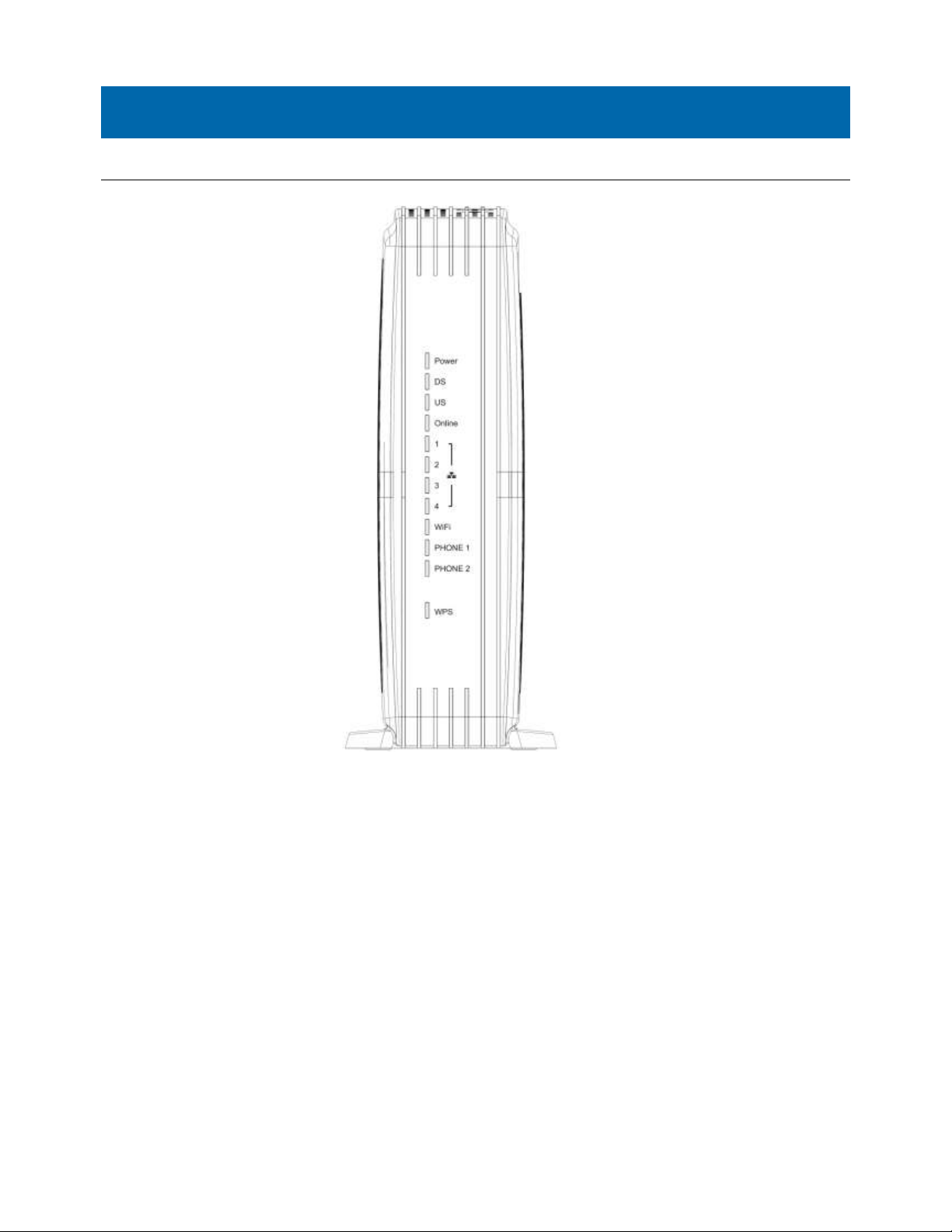
Front Panel
The following illustration shows the front panel of the EMTA:
Power - Indicates the Power status.
DS - Indicates the status of Data reception by the cable modem from the Network (Downstream Traffic).
US - Indicates the status of Data transmission by the cable modem to the Network (Upstream Traffic).
Online - Displays the status of your cable connection. The light is off when no cable connection is
detected and fully lit when the modem has established a connection with the network and data
can be transferred.
Ethernet - Indicates the state of Ethernet ports.
WIFI - Indicates the traffic on the wireless network.
Phone1 - Indicates the status of the telephone Phone 1.
Phone2 - Indicates the status of the telephone Phone 2.
WPS - Indicates the status of the WPS functionality.
3
Illustrations contained in this document are for representation only.
Page 7

Chapter 2: Overview
4
X
X
X
X
X
X
X
X
X
OFF
ON
FLASH
X
LED Behavior
There will be 12 LEDs on TCG220. Looking at LED from TOP to Bottom: Power, DS, US, Online, LAN1,
LAN2, LAN3, LAN4, WiFi, PHONE1, PHONE2, WPS. "ON" = the LED is light, "OFF" = the LED is gray,
"FLASH" = the LED is blinking.
BCM93383WVG Power
Internet LAN
DS US Online 1 2 3
Wi-Fi Phone1 Phone2 WPS Description
Boot-up Operation
DOCSIS Start-up
Operation
MTA initialization
ON ON ON ON
On 0.25 second
ON FLASH FLASH FLASH X X X
ON ON ON
ON
1 second DS scanning
ON FLASH OFF OFF X X X
ON ON FLASH OFF X X X
ON ON ON FLASH X X X
ON ON ON ON X X X
ON FLASH FLASH OFF X X X
ON ON ON ON X X X
ON ON ON ON X X X
ON ON ON ON X X X
ON ON ON ON X ON ON X
X X X X X X X X
Power on 0.25 sec
X X X X
X X X X
X X X X
X X X X
X X X X Operational (NACO=ON)
X X X X Operational (NACO=OFF)
X FLASH OFF X MTA DHCP
X OFF FLASH X MTA SNMP/TFTP
X FLASH FLASH X RSIP for NCS/Register for SIP
From power ON to system
initialization complete
Following system initialization
complete to (before)
During DS scanning and acquiring
SYNC
From SYNC completed, receiving
UCD to ranging completed
During DHCP, configuration file
download, registration, and
Baseline Privacy initialization
OFF OFF OFF
CPE Operation
SW Download
Operation
ON X X X
ON X X X X X X X
ON FLASH FLASH ON X X X
ON ON ON
FLASH FLASH FLASH
X X X X
OFF
X X X
ON Wireless initiate success or enable
FLASH TX/RX Wireless Traffic
X X X X
WPS Operation ON <CM Normal Operation> X X
4
Illustrations contained in this document are for representation only.
No Ethernet Link
Ethernet Link
TX/RX Ethernet Traffic
Wireless is disable
A software download and while
updating the FLASH memory
(long press, > 5 seconds)
WPS WiFi association during client
Flash
and AP linking process, WPS LED
Green color light Blinking.
After link established WPS LED
ON
Green color light ON
Flash Timeout to link.
Page 8
Chapter 2: Overview
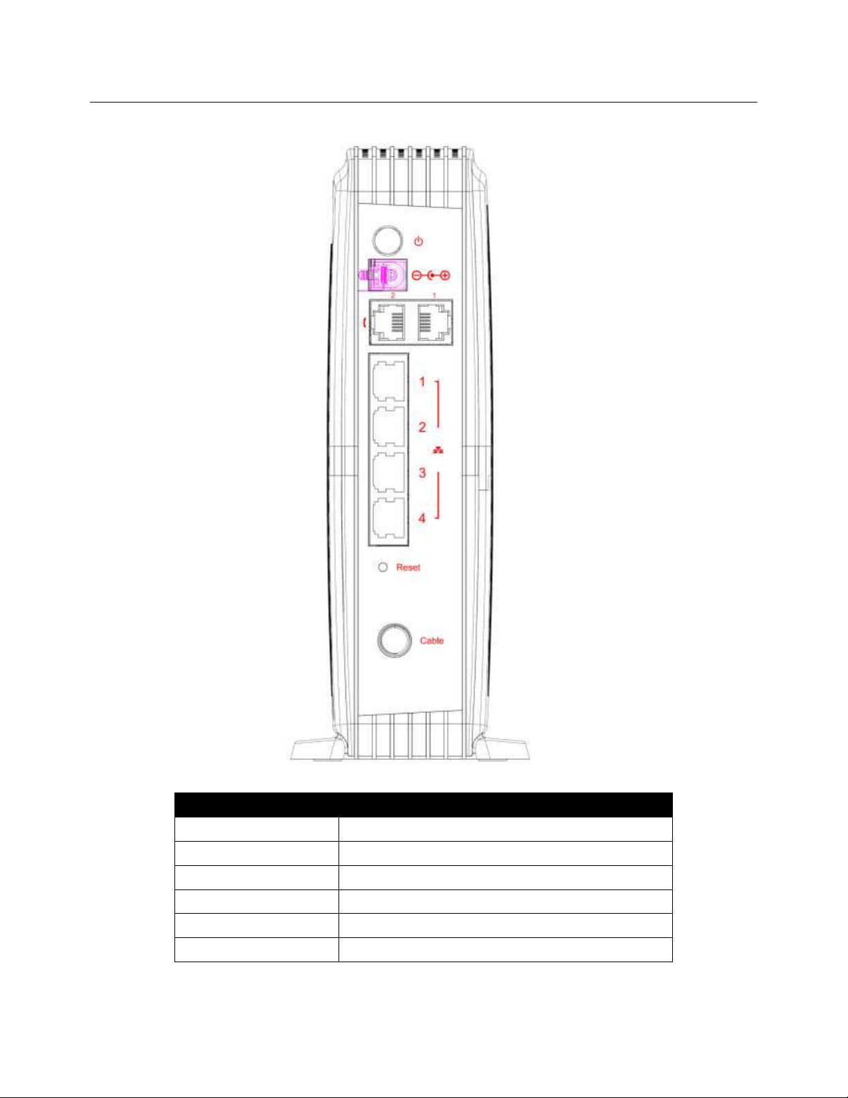
Rear Panel
The following illustration shows the rear panel of the EMTA:
Slot Description
CABLE F-Connector
RESET Reset/Reboot this Cable modem
ETHERNET 1 2 3 4 Ethernet 10/100/1000 BaseT RJ-45 connector
TEL 1 2 Telephony RJ-11 connector
12VDC 12V DC-IN Power connector
DC Power switch Power ON/ OFF switch
5
Illustrations contained in this document are for representation only.
Page 9
Chapter 2: Overview
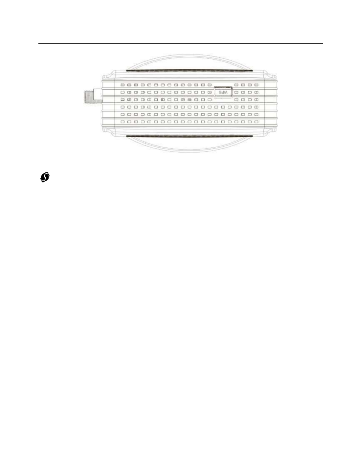
Top Side Panel for WPS
WPS ʹ Indicates the status of the WPS (Wi-Fi Protected SetupTM) functionality.
There is one WPS button on the Top Side Panel of TCG220 and is designed to have multiple function.
This button can be used to:
Securely and Simply Get WiFi Client Connected: WPS button can be used to paring WiFi client
which also supports WPS function. A long press (press more than 2 seconds) on the WPS button
will enable TCG220 scan for any available WPS device. Note: You must ensure that the WiFi client
device supports WPS function in order to use this WPS function on TCG220.
WiFi On/Off Switch: a short press on the button can switch the WiFi Interface ON or OFF
6
Illustrations contained in this document are for representation only.
Page 10

Chapter 2: Overview
Important Information
z The cable service to your home supports DOCSIS compliant two-way modem access.
z Your internet account has been set up.
z A cable outlet near your PC and it is ready for cable modem service.
Note: It is important to supply power to the modem at all times. Keeping your modem plugged in will
keep it connected to the Internet. This means that it will always be ready when you are. Your cable
company should always be consulted before installing a new cable outlet. Do not attempt any rewiring
without contacting your cable company first.
7
Illustrations contained in this document are for representation only.
Page 11

Chapter 3: Connections and setup
Chapter 3: Connections and setup
Connecting the EMTA to Computer
This section explains the way to attach Cable TV wire to EMTA and to connect your EMTA to the
Ethernet port on your personal computer and install the necessary software.
Attaching the Cable TV Wire to EMTA
You may find the Cable TV wire one of the following ways:
z Connected directly to a TV, a Cable TV converter box, or VCR. The line will be connected to the jack
with which should be labeled either IN, CABLE IN, CATV, CATV IN, etc.
z Connected to a wall-mounted cable outlet.
Connect one end of the coaxial cable to the cable connection in the wall, and the other end to the CABLE
jack on the EMTA.
8
Illustrations contained in this document are for representation only.
Page 12
Chapter 3: Connections and setup
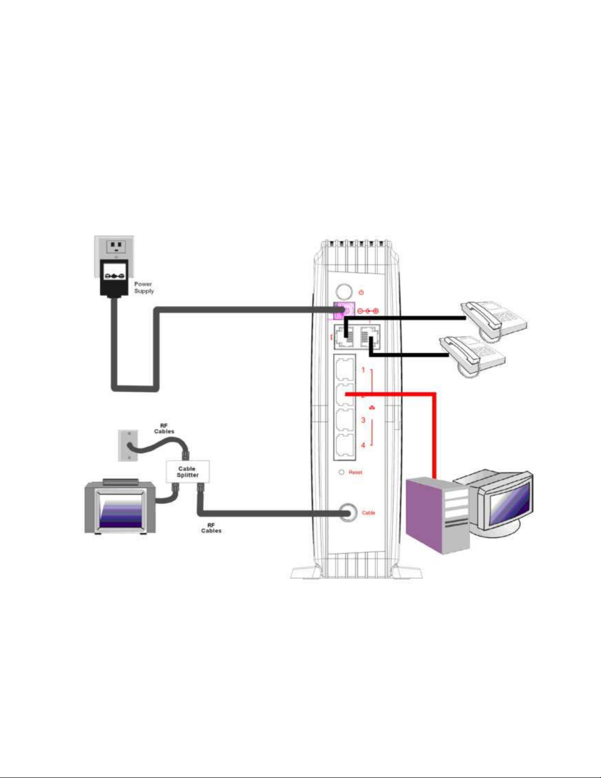
Connection to Computer and Telephone
Make the connections to modem in the following sequence:
z Connect the plug from the AC power supply into the POWER AC ADAPTER jack on the EMTA, and
plug the power supply into an AC outlet in the wall.
z Connect one end of the Ethernet cable to the Ethernet port on the back of your computer, and the
other end to the ETHERNET port on the EMTA.
Note: Use only the power
supply that accompanied this
unit. Using other adapters
may damage the unit.
Fig. 1: How to Setup Your Device
9
Illustrations contained in this document are for representation only.
Page 13

Chapter 3: Connections and setup
Activating the EMTA
After you install the EMTA and turn it on for the first time (and each time the modem is reconnected to
the power), it goes through several steps before it can be used. Each of these steps is represented by a
different pattern of flashing lights on the front of the modem.
Note: All indicators flash once prior to the initialization sequence.
If all of the lights are flashing sequentially, it means the EMTA is automatically updating its system
software. Please wait for the lights to stop flashing. You cannot use your modem during this time. Do
not remove the power supply or reset the EMTA during this process.
To make sure that you can access the Internet successfully, please check the following first.
1. Make sure the connection (through Ethernet) between the EMTA and your computer is OK.
2. Make sure the TCP/IP protocol is set properly.
3. Subscribe to a Cable Company.
10
Illustrations contained in this document are for representation only.
Page 14
Chapter 3: Connections and setup
Accessing the Internet
If enabled by your service provider; please proceed as follows:
1. Once your host PC is properly configured.
2. Start your web browser and type the CM IP address on the URL field.
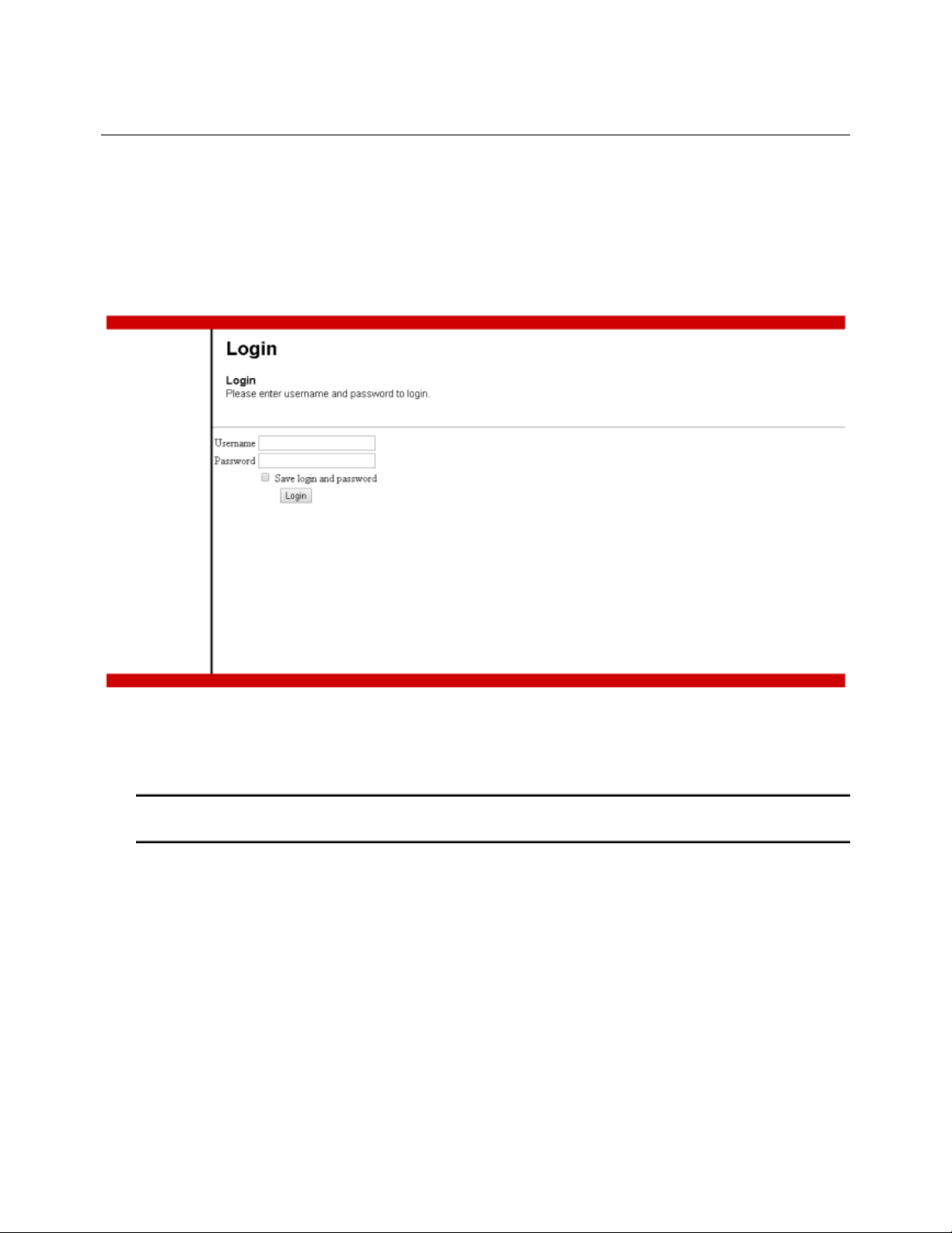
After connecting to the URL, you can see the login page. Please enter the username, password and then
press Login button. The default username is "admin" and password is "password".
Fig. 2: Login Page
Note: If forget your username and password, you may Press "Reset" button on the rear panel more
than 6seconds to restore the username and password to default.
11
Illustrations contained in this document are for representation only.
Page 15
Chapter 3: Connections and setup
Status Web Page Group
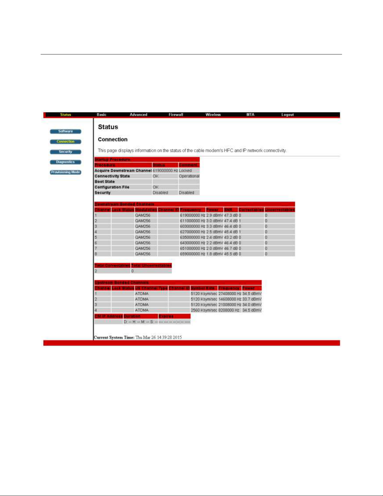
Connection
This page reports current connection status containing startup procedures, downstream and upstream
status, CM online information, and so on. The iŶĨŽƌŵĂƚŝŽŶĐĂŶďĞƵƐĞĨƵůƚŽLJŽƵƌĐĂďůĞĐŽŵƉĂŶLJƐ
ƐƵƉƉŽƌƚƚĞĐŚŶŝĐŝĂŶŝĨLJŽƵƌĞŚĂǀŝŶŐƉƌŽďůĞŵƐ
Fig. 3: Connection Status
12
Illustrations contained in this document are for representation only.
Page 16
Chapter 3: Connections and setup
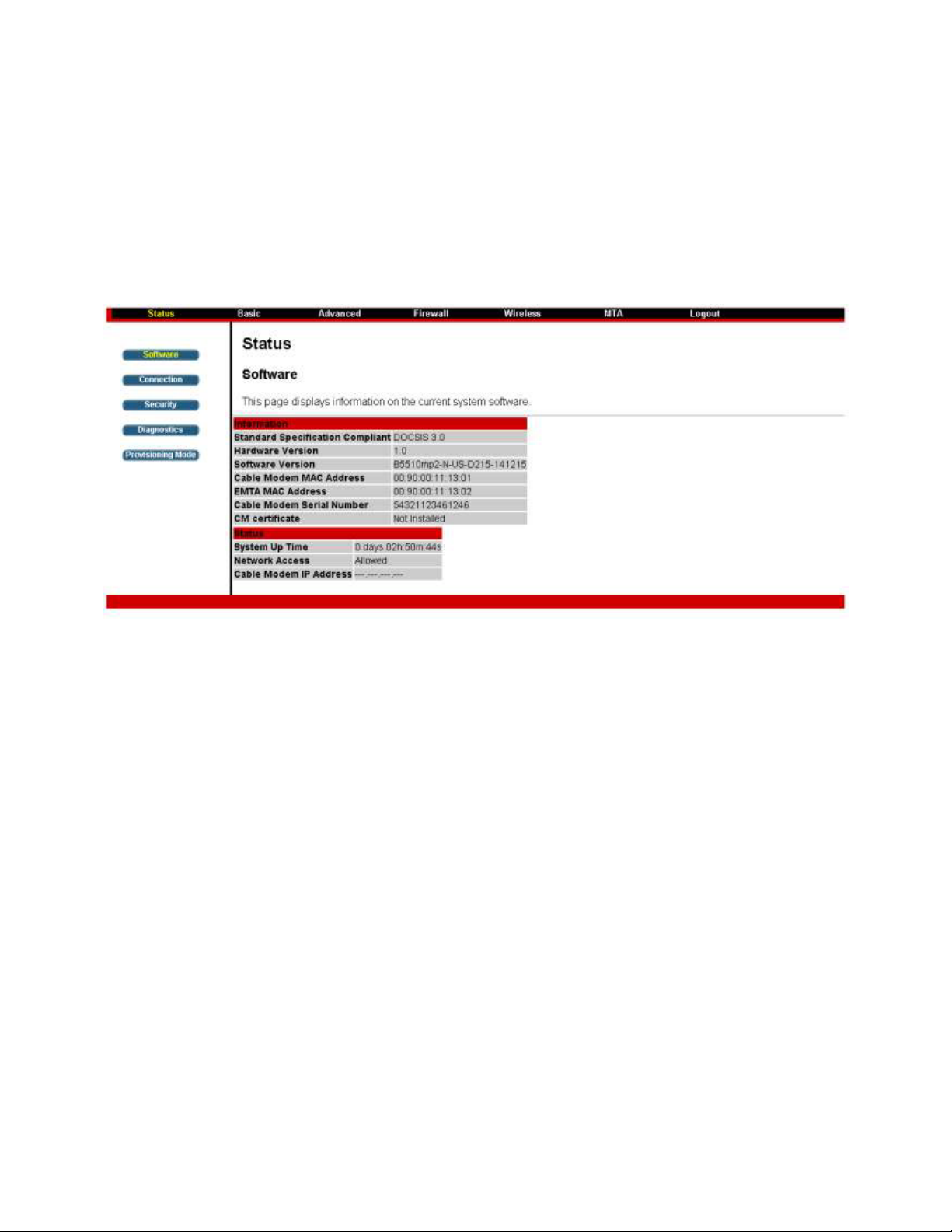
Software
The information section shows the hardware and software information about your gateway.
The status section of this page shows how long your gateway has operated since last time being
powered up, and some key information the Cable Modem received during the initialization process with
LJŽƵƌĐĂďůĞĐŽŵƉĂŶLJ/ĨEĞƚǁŽƌŬĐĐĞƐƐƐŚŽǁƐůůŽǁĞĚƚŚĞŶLJŽƵƌĐĂďůĞ company has configured your
gateway to have Internet connectivity. If not, you may not have Internet access, and should contact your
cable company to resolve this.
Fig. 4: Software Status
13
Illustrations contained in this document are for representation only.
Page 17
Chapter 3: Connections and setup
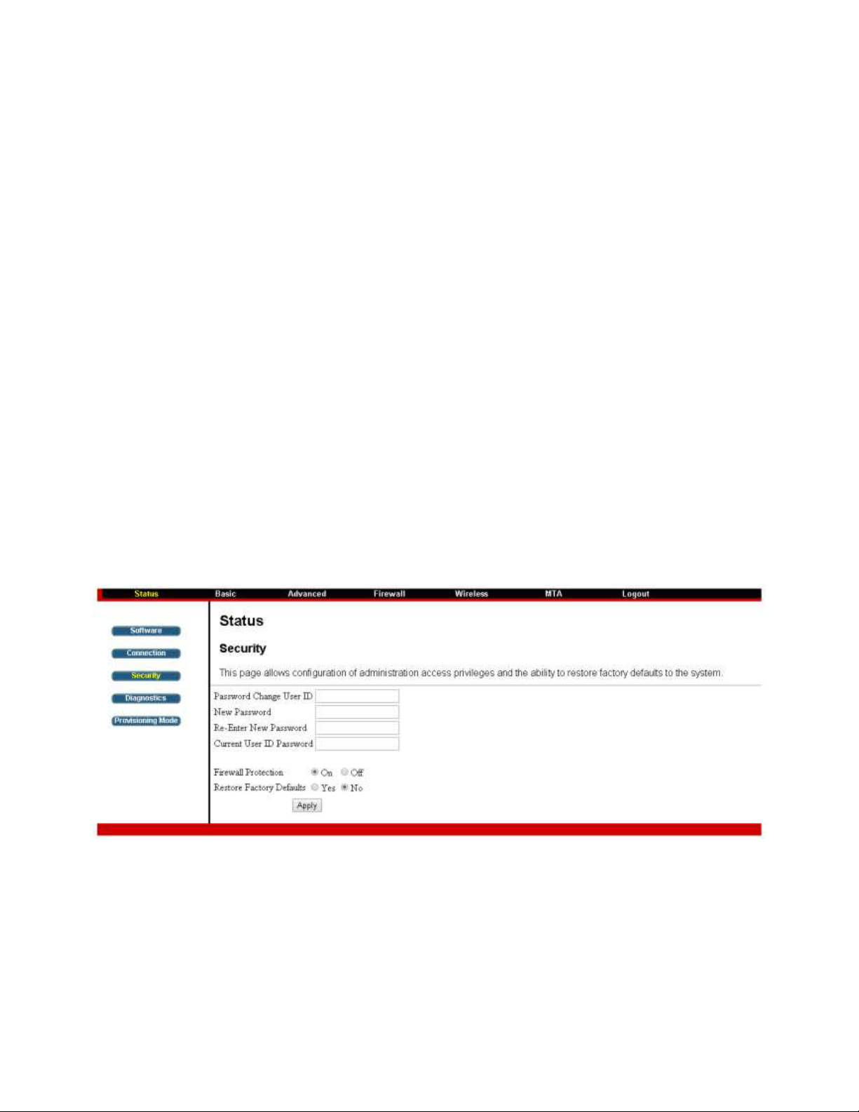
Security
LJĚĞĨĂƵůƚƚŚĞƵƐĞƌŶĂŵĞŝƐadminĂŶĚƚŚĞƉĂƐƐǁŽƌĚŝƐpassword
This is set by different actions (non exhaustive list):
- at the manufactory level,
- following a reset factory on the modem,
- following a reset from the operator,
- following a change by the user who wants to come back to
the default setting after using its own settings
When the current password is the default one, the user is strongly encouraged to change the default
web password.
At your first connection or while the password is the default one, a warning message is displayed on the
top banner of each Web configuration page. We want to encourage you to change the password in order
to enforce the security of your modem.
The password can be a maximum of 8 characters and is case sensitive. In addition, this page can be used
to restore the gateway to its original factory settings. Use this with caution, as all the settings you have
made will be lost. To perform this reset, set Restore Factory Defaults to Yes and click Apply. This has
the same effect as a factory reset using the rear panel reset switch, where you hold on the switch for 5
seconds, then release it.
Note: We are always suggesting you to modify the password. This is a basic protection against wrongful
access to the Gateway Web pages.
Fig. 5: Security Settings.
14
Illustrations contained in this document are for representation only.
Page 18
Chapter 3: Connections and setup
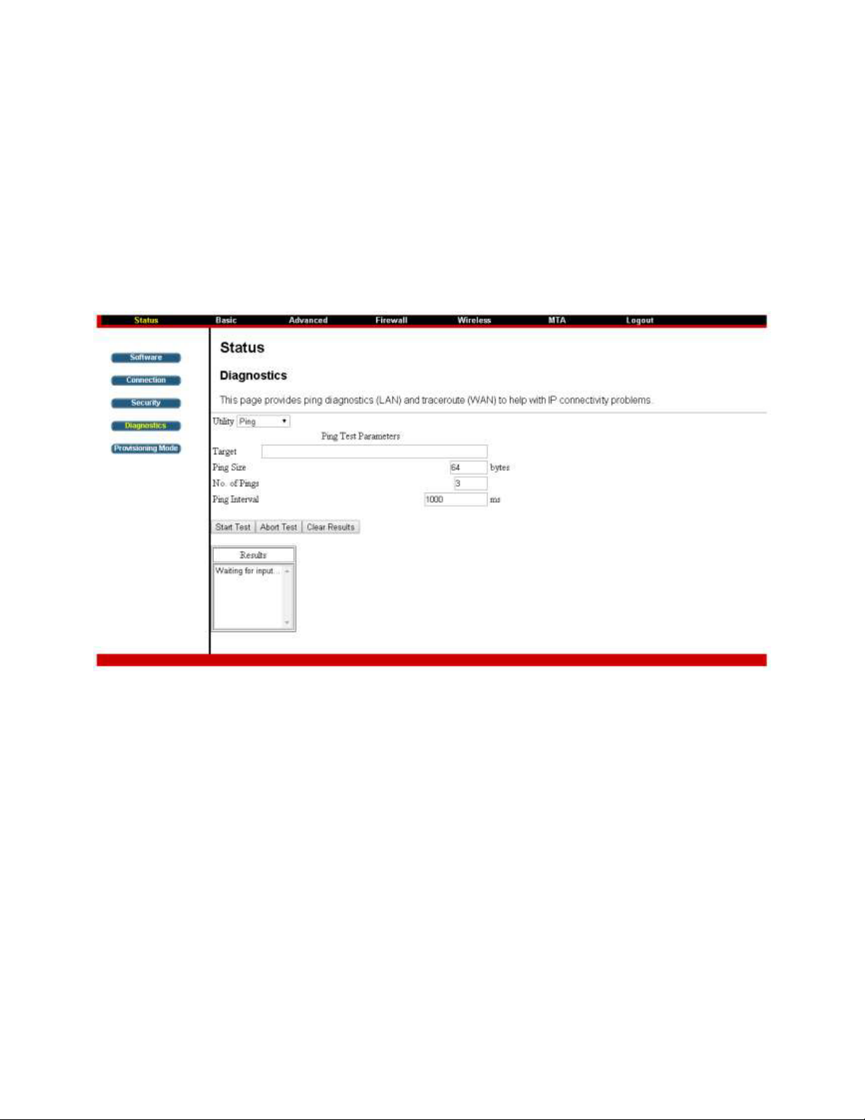
Diagnostics
This page offers basic diagnostic tools for you to use when connectivity problems occur. When you ping
an Internet device, you send a packet to its TCP/IP stack, and it sends one back to yours. To use the ping
Test, enter the information needed and press Start Test; the Result will be displayed in the lower part of
the window. Press Abort Test to stop, and Clear Results to clear the result contents. Note: Firewalls may
cause pings to fail but still provide you TCP/IP access to selected devices behind them. Keep this in mind
when ping a device that may be behind a firewall. Ping is most useful to verify connectivity with PCs
which do not have firewalls, such as the PCs on your LAN side.
Fig. 6: Diagnostics Settings
15
Illustrations contained in this document are for representation only.
Page 19

Chapter 3: Connections and setup
Provisioning Mode
This page allows set the eRouter IP provisioning mode. Default Provisioning mode is "RG". You can also
configure this as "Bridge" mode. Configure TCG220 to Bridge mode will lost most of the Router function.
Fig. 7: Provisioning mode settings.
16
Illustrations contained in this document are for representation only.
Page 20

Chapter 3: Connections and setup
Basic Web Page Group
Setup
This page allows configuration of the basic features of the broadband gateway related to your ISP's
connection.
LAN: Configure the LAN IP Address for TCG220.
Interface/Prefix: IPv6 related information.
WAN: TCG220 WAN interface information. Do NOT change the configuration setting which may cause
severe performance impact, or Client PC may not be able to get internet connected.
Fig. 8: Basic Setup Settings
17
Illustrations contained in this document are for representation only.
Page 21

Chapter 3: Connections and setup
DHCP
This page allows configuration and status of the optional internal DHCP server for the LAN.
You can activate the DHCP server function for the LAN on this page, with this function activated,
ͻ LJŽƵƌĐĂďůĞĐŽŵƉĂŶLJƐ,WƐĞƌǀĞƌƉƌŽvides one IP address for your gateway,
ͻ ĂŶĚLJŽƵƌŐĂƚĞǁĂLJƐ,WƐĞƌǀĞƌƉƌŽǀŝĚĞƐ/WĂĚĚƌĞƐƐĞƐ to your PCs. A DHCP server leases an IP
address with an expiration time that can be configured.
DHCP Server: Select "Yes" or "No" to enable or disable a simple DHCP server for LAN.
Number of CPEs: Configure the how many client device can be connected to the Gateway.
Lease Time: Configure the IP address lease time with "Lease time" for DHCP server. Default value is
3600 seconds.
DHCP Clients: Displays the PC(clients) connected and the related DHCP lease information.
Force Available: You can force the DHCP server to release one of the specific IP address as available and
a new client is possible to get that IP address, assigned by DHCP server. You need to select and then
press "Force Available".
Fig. 9: DHCP Settings
18
Illustrations contained in this document are for representation only.
Page 22

Chapter 3: Connections and setup
DDNS
This page allows setup of Dynamic DNS service.
z DDNS Service- Choose Enabled ( www.DynDNS.org ) to enable the basic setting. Choose
Disabled to close the basic setting.
z Username- The username that you registered with your DDNS provider.
z Password- The password that you registered with your DDNS provider
z Host Name- The domain name or host name that is registered with your DDNS provider
z Status- It shows the DDNS service status whether it is enabled or disabled.
Click Apply to save the changes.
Fig. 10: DDNS Settings
19
Illustrations contained in this document are for representation only.
Page 23

Chapter 3: Connections and setup
Backup
This page allows you to save your current settings locally on your PC, or restore settings previously
saved. Customer may backup their settings on TCG220. And restore the configuration if necessary.
Fig. 11: Backup Settings
20
Illustrations contained in this document are for representation only.
Page 24

Chapter 3: Connections and setup
Advance Web Page Group
Option
This page allows configuration of advanced features of the broadband gateway.
Fig. 12: Options Configuration
WAN Blocking prevents others on the WAN side from being able to ping your gateway. With WAN
Blocking enabled, your gateway will not respond to pings it receives, effectively "hiding" your gateway.
21
Illustrations contained in this document are for representation only.
Page 25

Chapter 3: Connections and setup
IPsec PassThrough enables IPsec type packets to pass between WAN and LAN. IPsec (IP Security) is a
security mechanism used in Virtual Private Networks (VPNs).
PPTP PassThrough enables PPTP type packets to pass between WAN and LAN. PPTP (Point to Point
Tunneling Protocol) is another mechanism sometimes used in VPNs.
Remote Config Management makes the configuration web pages in your gateway accessible from the
WAN side. Note that page access is limited to only those who know the gateway access password. When
accessing your gateway from a remote location, your must use HTTP port 8080 and the WAN IP address
of the gateway. e.g., if the WAN IP address is 157.254.5.7, you would navigate to
http://157.254.5.7:8080 to reach your gateway.
Multicast Enable enables multicast traffic to pass through WAN and LAN. You may need to enable this
to see some types of broadcast streaming and content on the Internet.
UPnP Universal Plug and Play (UPnP) helps devices, such as Internet appliances and computers, access
the network and connect to other devices as needed. UPnP devices can automatically discover the
services from other registered UPnP devices on the network.
NAT ALG enable NAT ALG (application layer gateways) allows customized NAT traversal filters to be
plugged into the gateway to support address and port translation for certain application layer
"control/data" protocols such as RSVP, FTP, TFTP, Kerb88, NetBios , IKE, RTSP, Kerb1293 , H225 , PPTP ,
MSN , SIP , ICQ , IRC666x , ICQTalk , Net2Phone , IRC7000 , IRC8000 file transfer in IM applications etc. In
order for these protocols to work through NAT or a firewall, either the application has to know about an
address/port number combination that allows incoming packets, or the NAT has to monitor the control
traffic and open up port mappings (firewall pinhole) dynamically as required. Legitimate application data
can thus be passed through the security checks of the firewall or NAT that would have otherwise
restricted the traffic for not meeting its limited filter criteria.
22
Illustrations contained in this document are for representation only.
Page 26

Chapter 3: Connections and setup
IP Filtering
dŚŝƐƉĂŐĞĞŶĂďůĞƐLJŽƵƚŽĞŶƚĞƌƚŚĞ/WĂĚĚƌĞƐƐƌĂŶŐĞƐŽĨWƐŽŶLJŽƵƌ>EƚŚĂƚLJŽƵĚŽŶƚǁĂŶƚƚŽŚĂǀĞ
outbound access to the WAN. These PCs can still communicate with each other on your LAN, but
packets they send to WAN addresses are blocked by the gateway.
Fig. 13: IP Filtering Settings
23
Illustrations contained in this document are for representation only.
Page 27

Chapter 3: Connections and setup
MAC Filtering
This page allows configuration of MAC address filters in order to block internet traffic to specific
network devices on the LAN. This feature only applies to IPv4 traffic.
Fig. 14: MAC Filtering Settings
24
Illustrations contained in this document are for representation only.
Page 28

Chapter 3: Connections and setup
Port Filtering
dŚŝƐƉĂŐĞĂůůŽǁƐLJŽƵƚŽĞŶƚĞƌƌĂŶŐĞƐŽĨĚĞƐƚŝŶĂƚŝŽŶƉŽƌƚƐ;ĂƉƉůŝĐĂƚŝŽŶƐͿƚŚĂƚLJŽƵĚŽŶƚǁĂŶƚLJŽƵƌ>E
PCs to send packets to. Any packets your LAN PCs send to these destination ports will be blocked. For
example, you could block access to worldwide web browsing (http = port 80) but still allow email service
(SMTP port 25 and POP-3 port 110). To enable port filtering, set Start Port and End Port for each range,
and click Apply. To block only one port, set both Start and End ports with the same value.
Fig. 15: Port Filtering Settings
25
Illustrations contained in this document are for representation only.
Page 29

Chapter 3: Connections and setup
Forwarding
For LAN Ù WAN communications, the gateway normally only allows you to originate an IP connection
with a PC on the WAN; it will ignore attempts of the WAN PC to originate a connection onto your PC.
This protects you from malicious attacks from outsiders. However, sometimes you may wish for anyone
outside to be able to originate a connection to a particular PC on your LAN if the destination port
(application) matches one you specify.
Fig. 16: Forwarding Settings
26
Illustrations contained in this document are for representation only.
Page 30

Chapter 3: Connections and setup
Port Triggers
Some Internet activities, such as interactive gaming, require that a PC on the WAN side of your gateway
be able to originate connections during the game with your game playing PC on the LAN side. You could
use the Advanced-Forwarding web page to construct a forwarding rule during the game, and then
remove it afterwards (to restore full protection to your LAN PC) to facilitate this. Port triggering is an
elegant mechanism that does this work for you, each time you play the game.
Fig. 17: Port Triggers Settings
27
Illustrations contained in this document are for representation only.
Page 31

Chapter 3: Connections and setup
DMZ Host
Use this page to designate one PC on your LAN that should be left accessible to all PCs from the WAN
side, for all ports. e.g., if you put an HTTP server on this machine, anyone will be able to access that
HTTP server by using your gateway IP address as the destination. A ƐĞƚƚŝŶŐŽĨϬŝŶĚŝĐĂƚĞƐEKDW
,ŽƐƚŝƐĂŶŽƚŚĞƌ/ŶƚĞƌŶĞƚƚĞƌŵĨŽƌĂWĐŽŶŶĞĐƚĞĚƚŽƚŚĞ/ŶƚĞƌŶĞƚ
Fig. 18: DMZ Host Setup
28
Illustrations contained in this document are for representation only.
Page 32

Chapter 3: Connections and setup
RIP (Routing Information Protocol Setup)
This feature enables the gateway to be used in small business situations where more than one LAN
;ůŽĐĂůĂƌĞĂŶĞƚǁŽƌŬͿŝƐŝŶƐƚĂůůĞĚdŚĞZ/WƉƌŽƚŽĐŽůƉƌŽǀŝĚĞƐƚŚĞŐĂƚĞǁĂLJĂŵĞĂŶƐƚŽĂĚǀĞƌƚŝƐĞĂǀĂŝůĂďůĞ
IP routes to these LANs to your cable operator, so packets can be routed properly in this situation.
Your cable operator will advise you during installation if any setting changes are required here.
Fig. 19: RIP Setup
29
Illustrations contained in this document are for representation only.
Page 33

Chapter 3: Connections and setup
Firewall Web Page Group
Basic
This page allows configuration of Firewall features. It is highly recommended that the Firewall is left
enabled at all times for protection against Denial of Service attacks.
Fig. 20: Firewall Basic configuration
30
Illustrations contained in this document are for representation only.
Page 34

Chapter 3: Connections and setup
Filtering
This page allows the filtering of outbound connections, restricting or granting access to specific MAC
Addresses. Filters with no MAC Address entered will apply to ALL MAC Addresses. The URL field is
intended to be used to block or allow access to specific sites ( cnn.com, google.com, etc. ). Filters with
no ports entered will apply to ALL ports.
Fig. 21: Filtering configuration
31
Illustrations contained in this document are for representation only.
Page 35

Chapter 3: Connections and setup
Local Log
The gateway builds a log of firewall blocking actions that the firewall has taken. Using the Local Log page
lets you specify an email address to which you want the gateway to email this log. You must also tell the
gateway your outgoing (i.e. SMTP) email seƌǀĞƌƐŶĂŵĞƐŽŝƚĐĂŶĚŝƌĞĐƚƚŚĞĞŵĂŝůƚŽŝƚŶĂďůĞŵĂŝů
Alerts has the gateway forward email notices when Firewall protection events occur. Click E-mail Log to
immediately send the email log. Click Clear Log to clear the table of entries for a fresh start.
The log of these events is also visible on the screen. For each blocking event type that has taken place
since the table was last cleared, the table shows Description, Count, Last Occurrence, Target, and
Source.
Fig. 22: Local Log Configuration
32
Illustrations contained in this document are for representation only.
Page 36

Chapter 3: Connections and setup
Remote Log
The Remote Log page allows you to specify the IP address where a SysLog server is located on the LAN
Side and select different types of firewall events that may occur. Then, each time such an event occurs,
notification is automatically sent to this log server.
Fig. 23: Remote Log Configuration
33
Illustrations contained in this document are for representation only.
Page 37

Chapter 3: Connections and setup
Wireless Web Page Group
Radio
To set the basic configuration for the wireless features, click RADIO from the Wireless menu. These must
match the settings you make on your wireless-equipped PC on the LAN side.
Fig. 24: Radio configuration
Wireless Interface:
Choose the wireless interface on the EMTA.
Wireless:
Enable or disable the wireless function.
Country:
Display the country code you currently use.
Output Power:
Choose output power of the device.
802.11 Band:
Choose 2.4 GHz for 802.11 b/g/n, 5 GHz for 802.11a
802.11 N Support Required:
Enable 802.11n support under 802.11 band 2.4 GHz.
34
Illustrations contained in this document are for representation only.
Page 38

Chapter 3: Connections and setup
Bandwidth:
For wireless signal of this AP
Sideband for Control Channel (40 MHz only):
If Bandwidth is 40 MHz this function will be enabled.
Control channel:
Choose the wireless channel to use.
Regulatory Mode:
802.11d and 802.11h for choose.
OBSS (Overlap Basic Service Set) Coexistence:
Overlapping Basic service set coexistence, enable or disable this function.
STBC Tx:
Spaceʹtime block coding is a technique used in wireless communications to transmit multiple
copies of a data stream across a number of antennas and to exploit the various received versions
of the data to improve the reliability of data-ƚƌĂŶƐĨĞƌĞĨĂƵůƚǁĂƐƵƚŽ
Restore Wireless defaults:
To recover to the default settings, press this button to retrieve the settings then click Apply.
35
Illustrations contained in this document are for representation only.
Page 39

Chapter 3: Connections and setup
Primary Network
This page allows configuration of the Primary Wireless Network and its security settings. Supports
WPA/WPA2, WPA-PSK/WPA2-PSK, WEP 64-bits, WEP 128-bits and WPS Securities.
Fig. 25: primary Network configuration
36
Illustrations contained in this document are for representation only.
Page 40

Chapter 3: Connections and setup
WPA (Wi-Fi Protected Access)/WPA2:
It must be used in connection with an authentication server such as RADIUS to provide
centralized access control and management. It can provide stronger encryption and
authentication solution than none WPA modes. WPA2 is the second generation of WPA security.
There are two types for choose AES and TKIP+AES.
TKIP (Temporal Key Integrity Protocol): Takes the original master key only as a starting point and
derives its encryption keys mathematically from this mater key. Then it regularly changes and
rotates the encryption keys so that the same encryption key will never be used twice.
AES (Advanced Encryption Standard): This Provides security between client workstations
operating in ad hoc mode. It uses a mathematical ciphering algorithm that employs variable key
sizes of 128, 192 or 256 bits.
RADIUS (Remote Authentication Dial In User Service) Server:
a protocol for carrying authentication, authorization, and configuration information between a
Network Access Server which desires to authenticate its links and a shared Authentication Server.
Please key in the IP Address for the RADIUS Server.
RADIUS (Remote Authentication Dial In User Service) Port:
Besides the IP address of the RADIUS Server, you have to enter the port number for the server.
Port 1812 is the reserved RADIUS-authentication port described in RFC 2138. Earlier AP (RADIUS
clients) use port 1945. The default value will be shown on this box. You can keep and use it.
RADIUS (Remote Authentication Dial In User Service) Key:
A RADIUS Key is like a password, which is used between IAS and the specific RADIUS client to
verify identity. Both IAS and the RADIUS client must be use the same RADIUS Key for successful
communication to occur. Enter the RADIUS Key.
Group Key Rotation Interval:
Key in the time for the WAP group key rotation interval. The unit is second. With increasing rekey
interval, user bandwidth requirement is reduced
WPA/WPA2 Re-auth Interval:
When a wireless client has associated with the Wireless Voice Gateway for a period of time
longer than the setting here, it would be disconnected and the authentication will be executed
again. The default value is 3600, you may modify it
WPA-PSK (WPA-Pre-Shared Key) /WPA2-PSK:
Its useful for small places without authentication servers such as the network at home. It allows
the use of manually-entered keys or passwords and is designed to be easily set up for home
users.
Please type the key to be between 8 and 63 characters, or 64 hexadecimal digits. Only the
devices with a matching key that you set here can join this network.
WEP (Wired Equivalent Privacy) Encryption:
There are two types encryption to choose 64-bit or 128-bit. If you choose Disabled, the Network
37
Illustrations contained in this document are for representation only.
Page 41

Chapter 3: Connections and setup
Keys will not be shown on this page. If selected, the data is encrypted using the key before being
transmitted.
Shared Key Authentication:
Decide whether to set the shared key Optional or Required by selecting from the drop-down
menu.
Network Key 1 to 4:
This allows you to enter four sets of the WEP key. For 64-bit WEP mode, the key length is 5
characters or 10 hexadecimal digits. As for 128-bit WEP mode, the key length is 13 characters or
26 hexadecimal digits
Current Network Key:
Select one set of the network key (from 1 to 4) as the default one
Passphrase:
You can enter ASCII codes into this field. The range is from 8 characters to 64 characters. For
ASCII characters, you can key in 63 characters in this field. If you want to key in 64 characters,
only hexadecimal characters can be used
Generate WEP Keys:
Click this button to generate the Passphrase
38
Illustrations contained in this document are for representation only.
Page 42
Chapter 3: Connections and setup
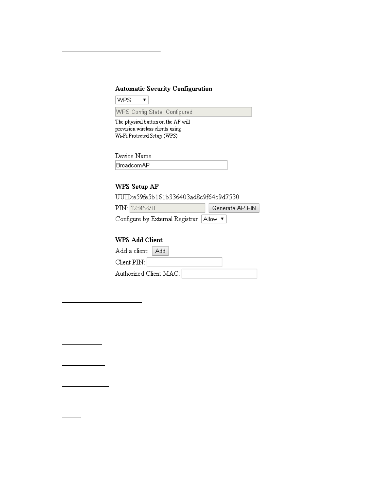
Automatic Security Configuration:
Right side on the page, Auto Security Configuration can be enabled with WPS (Wi-Fi Protect
TM
Setup
).
TM
WPS (Wi-Fi Protect Setup
):
Its easy and secure way of configuring and connecting, make the CM is the AP and the connect
PC is STA. When configuring your Wireless Network via WPS, Messages are exchanged between
the STA and AP in order to configure the Security Settings on both devices
Device Name:
Change the factory default to a name of your choice which is up to 32 characters long as like SSID
WPS Setup AP:
UUID (Universally Unique Identifier) to Identifier this device, generate AP PIN for STA to connect.
WPS Add Client:
There are two methods "Push-Button" and "PIN". Select the method you want. But, the default
selection will be "PIN"
Apply:
After proper configuration, click Apply to invoke the settings
39
Illustrations contained in this document are for representation only.
Page 43

Chapter 3: Connections and setup
802.11 Advanced
This page allows configuration of data rates and Wi-Fi thresholds.
CAUTION: It is not recommended that these settings be modified without direct knowledge or
instructions to do so. Modifying these settings inappropriately could seriously degrade network
performance.
Fig. 26: 802.11 Advanced Settings
TM
54g
Mode:
Under 802.11n-mode OFF this option to choose 54g mode or force 802.11b only.
TM
XPress
Technology:
Increase aggregate throughput improve by up to 27% in 802.11g-only networks, and up to 75%
in mixed networks comprised of 802.11g and 802.11b standard equipment
802.11n Protection:
This option allow 802.11g and 802.11b devices co-exist in the same network without "speaking"
at the same time.
Short Guard Interval:
For 802.11n added optional to increase data rate. This provides an 11% increase in data rate.
Basic Rate Set:
For all clients to associate with, "Default" or "All" for all 802.11 b/g/n users.
40
Illustrations contained in this document are for representation only.
Page 44

Chapter 3: Connections and setup
Multicast Set:
For users, in order to connect to the AP, set the baseline level to deliver. Lower multicast rates
mean weaker, farther signals are allowed to connection. Higher multicast rates mean that only
close, strong signals are allowed.
NPHY Rate:
Set Physical Layer rate, only applicable when the 802.11n-mode set as auto.
Legacy Rate:
When AP released to share the band with existing legacy device, 802.11g/b/a devices. It
provided ways of ensuring coexistence between legacy and successor devices.
Beacon Interval:
This is the time interval between beacon transmissions. The measure unit is "time units" (TU) of
1024 microseconds. (Value range: 1~65535)
DTIM (Delivery Traffic Indication Message) Interval:
The value set here which informs the clients about the presence of buffered multicast/broadcast
data on the AP. It define CM will be delivered and how often that delivery occurs. (Value range:
1~255)
Fragmentation Threshold:
This option division of the MTU (Maximum transmission unit), default is 2346.
RTS (Request to Send) Threshold:
Sending RTS frames does not occur unless the packet size exceeds this threshold, default is 2347.
41
Illustrations contained in this document are for representation only.
Page 45

Chapter 3: Connections and setup
802.11 Access Control
This page allows configuration of the Access Control to the AP as well as status on the connected clients.
Fig. 27: 802.11 Access Control configurations
MAC Restrict Mode: Restrict specific client cannot allow access the AP by MAC address. Select
"Disabled" to welcome all of the clients on the network; select "Allow" to permit only the clients
on the list to access the cable modem; or select "Deny" to prevent the clients on the list to
access this device.
MAC Address
: Your Gateway identifies wireless PCs by their Wireless MAC Address. This address
consists of a string of 6 pairs of numbers 0-9 and letters A-F, such as 00 90 4B F0 FF 50. It is
usually printed on the Wireless card of the device (e.g. the PCMCIA card in a laptop) or at the
button of the laptop. Enter the MAC address of the connected clients into the fields, and then
click Apply to add them to the list for access control.
: After proper configuration, click Apply to invoke the settings.
Apply
Connected Clients
: The information of currently connected clients will be displayed here.
42
Illustrations contained in this document are for representation only.
Page 46

Chapter 3: Connections and setup
WMM
This page allows configuration of the Wi-Fi Multimedia QoS.
Fig. 28: 802.11 WMM configurations
WMM Support: This field allows you to enable WMM to improve multimedia transmission.
No-Acknowledgement
: This field allows you to enable WMM No-Acknowledgement. Enable this
avoids retransmission on highly time-critical data.
Power Save Support
EDCA AP parameters
: This field allows you to enable WMM Power-Save-Support.
: Specifies the transmit parameter for traffic transmitted from the AP to the
STA for the 4 Access Priority Categories: Best effort (AC_BE), Background (AC_BK), Video (AC_VI)
and voice (AC_VO). Transmit parameters include contention window (CWmin CWmax) ,
arbitration Inter Frame Spacing Number AIFSN, and Transmit opportunity Limit (TXOP limit).
Admission Control
specifies if admission control is enforced for the Access categories. Discard
Oldest first specified the discard policy for the queues , "On" discards the oldest first ; "Off"
discards the newest first.
EDCA STA parameters
: Specifies the transmit parameter for traffic transmitted from STA to the
AP for the 4 Access Priority Categories :Best effort (AC_BE), Background (AC_BK), Video (AC_VI)
43
Illustrations contained in this document are for representation only.
Page 47

Chapter 3: Connections and setup
and voice (AC_VO). Transmit parameters include contention window (CWmin CWmax) ,
arbitration Inter Frame Spacing Number AIFSN, and Transmit opportunity Limit (TXOP limit).
WMM TXOP parameters
effort (AC_BE), Background (AC_BK), Video (AC_VI) and voice(AC_VO). WMM Transmit
parameters include Short Retry Limit , Short Fallbk Limit , Long Retry Limit , Long Fallbk Limit.
Those retry limit defines how many times the MAC retries to send different types of packets. If
the number of retries reach their limit, the frame is discarded. Also we can set the Max Rate in
500kbps.
: Specifies the TXOP parameter for the 4 Access Priority Categories :Best
44
Illustrations contained in this document are for representation only.
Page 48

Chapter 3: Connections and setup
WDS
This page allows configuration of WDS (Wireless Distribution System) features.
Fig. 29: WDS configuration
TCG220 can allow to communicate with other "extender" wireless access points either exclusively or
mixed with communications to local PCs. Use this page to designate the remote devices, the gateway is
allowed to communicate with, and to select the WDS mode. You will need to configure the same SSID,
WiFi encryption mode and also the pass phrases for both TCG220 and remote WiFi gateway before you
can extend the WiFi network together.
WDS:
Choose Disabled to shut down this function; select Enabled to turn on the function of WDS.
Remote APs:
Enter the MAC Addresses of the remote devices to relay the signals for each other.
Apply:
After proper configuration, click Apply to invoke the settings.
45
Illustrations contained in this document are for representation only.
Page 49

Chapter 3: Connections and setup
Media
This page allows configuration of Wireless Media features.
Fig. 30: 802.11 Media Advanced Feature Configuration
Band Steering is a new feature that TCG220 has and will balancing the WiFi loading and
performance on both 2.4G and 5G band. When enabled, TCG220 will send 5G enabled client
which connected on 2.4G to the 5G interface (since TCG220 is a Dual Band Dual Concurrent
Cable Voice WiFi Gateway), vice versa. This will also requires the support from WiFi Client.
Airtime Fairness is a new feature that TCG220 has. If enabled, this will balance the WiFi
performance when High Throughput device such as 802.11n device and legacy 802.11b/g device
connected on the same channel. CG220 will dynamically allocate the time for transmission to
each device so that the performance to High Throughput device will not be severely affected by
the legacy device.
46
Illustrations contained in this document are for representation only.
Page 50

Chapter 3: Connections and setup
MTA Web Page Group
Status
This page displays initialization status of the MTA.
Event Log
This page displays the MTA Event Log.
Fig.31: MTA Status
Fig. 32: MTA Event Log
47
Illustrations contained in this document are for representation only.
Page 51

Chapter 3: Connections and setup
Logout Web Page Group
This page warning you are logged out, click "Back to Login" return to Login page.
Fig. 33: Logout Page
48
Illustrations contained in this document are for representation only.
Page 52

Chapter 4: Additional Information
Chapter 4: Additional Information
General Troubleshooting
You can correct most problems you have with your product by consulting the troubleshooting list that
follows.
I cannot access the Internet.
Check all of the connections to your EMTA.
Your Ethernet card may not be working well. Check the documentation for more information.
The Network Properties of your operating system may not be setting correctly. Check with your ISP or
cable company.
All of the lights are flashing in sequence.
This means the EMTA is automatically updating its system software. Please wait for the lights to stop
flashing. The updating process typically lasts less than one minute.
Do not remove the power supply or reset the EMTA during this process.
/ĐĂŶƚŐĞƚƚŚĞŵŽĚĞŵƚŽĞƐƚĂďůŝƐŚĂŶƚŚĞƌŶĞƚĐŽŶŶĞĐƚŝŽŶ
ǀĞŶŶĞǁĐŽŵƉƵƚĞƌƐĚŽŶƚĂůǁĂLJƐŚĂǀĞƚŚĞƌŶĞƚĐĂƉĂďŝůŝƚŝĞƐʹ be sure to verify that your computer has
a properly installed Ethernet card and the driver software to support it.
Check to see that you are using the right type of Ethernet cable.
The modem wonƚƌĞŐŝƐƚĞƌĂĐĂďůĞĐŽŶŶĞĐƚŝŽŶ;>>/E<ůŝŐŚƚŶŽƚŽŶĐŽŶƚŝŶƵŽƵƐůLJͿ
If the modem is in Initialization Mode, the INTERNET light will be flashing. Call your cable company if it
has not completed this 5-step process within 30 minutes.
The modem should work with a standard RG-ϲĐŽĂdžŝĂůĐĂďůĞďƵƚŝĨLJŽƵƌĞƵƐŝŶŐĂĐĂďůĞŽƚŚĞƌƚŚĂŶŽŶĞ
your cable company recommends, or if the terminal connections are loose, it may not work. Check with
your cĂďůĞĐŽŵƉĂŶLJƚŽĚĞƚĞƌŵŝŶĞǁŚĞƚŚĞƌLJŽƵƌĞƵƐŝŶŐƚŚĞĐŽƌƌĞĐƚĐĂďůĞ
If you subscribe to video service over cable, the cable signal may not be reaching the modem. Confirm
that good quality cable television pictures are available to the coaxial connector you are using by
connecting a television to it. If your cable outlet is "dead", call your cable company.
Verify that the EMTA service is DOCSIS compliant by calling your cable provider.
/ĚŽŶƚŚĞĂƌĂĚŝĂůƚŽŶĞǁŚĞŶ/ƵƐĞĂƚĞůĞƉŚŽŶĞ
Telephone service is not activated. If the rightmost light on the EMTA stays on while others flash, check
with your TSP or cable company.
49
Illustrations contained in this document are for representation only.
Page 53

Chapter 4: Additional Information
If the EMTA is connected to existing house telephone wiring, make sure that another telephone service
is not connected. The other service can normally be disconnected at the Network Interface Device
located on the outside of the house.
If using the second line on a two-line telephone, use a 2-line to 1-line adapter cable.
50
Illustrations contained in this document are for representation only.
Page 54

Chapter 4: Additional Information
Service Information
If you purchased or leased your EMTA directly from your cable company, then warranty service for the
EMTA may be provided through your cable provider or its authorized representative. For information on
the following, please contact your cable company. See the enclosed warranty card if you purchased your
EMTA from a retailer.
1) Ordering Service,
2) Obtaining Customer Support
3) Additional Service Information
51
Illustrations contained in this document are for representation only.
Page 55

Chapter 4: Additional Information
Glossary
10BaseT ʹ Unshielded, twisted pair cable with an RJ-45 connector, used with Ethernet LAN (Local Area
Network). "10" indicates speed (10 Mbps), "Base" refers to baseband technology, and "T" means twisted
pair cable.
Authentication - The process of verifying the identity of an entity on a network.
DHCP (Dynamic Host Control Protocol) ʹ A protocol with which allows a server to assign IP addresses
dynamically to hosts on the fly.
DOCSIS (Data Over Cable Service Interface Specifications) ʹ A project with the objective of developing a
set of necessary specifications and operations support interface specifications for cable modems and
associated equipment.
Ethernet card ʹ A plug-in circuit board installed in an expansion slot of a personal computer. The
Ethernet card (sometimes called a Network Interface Card or NIC) takes parallel data from the computer,
converts it to serial data, puts it into a packet format, and sends it over the 10BaseT or 100BaseT LAN
cable.
F Connector ʹ A type of coaxial connector, labeled CABLE IN on the rear of the cable modem that
connects the modem to the cable system.
HTTP (HyperText Transfer Protocol) ʹ Invisible to the user, HTTP is used by servers and clients to
communicate and display information on a web browser.
Hub ʹ A device used to connect multiple computers to the cable modem.
IP Address ʹ A unique, 32-bit address assigned to every device in a network. An IP (Internet Protocol)
address has two parts: a network address and a host address. This modem receives a new IP address
from your cable operator via DHCP each time it goes through Initialization Mode.
Key exchange - The swapping of mathematical values between entities on a network in order to allow
encrypted communication between them.
MAC Address ʹ The permanent "identity" for a device programmed into the Media Access Control layer
ŝŶƚŚĞŶĞƚǁŽƌŬĂƌĐŚŝƚĞĐƚƵƌĞĚƵƌŝŶŐƚŚĞŵŽĚĞŵƐŵĂŶƵĨĂĐƚƵƌing.
NID - Network Interface Device, the interconnection between the internal house telephone wiring and a
ĐŽŶǀĞŶƚŝŽŶĂůƚĞůĞƉŚŽŶĞƐĞƌǀŝĐĞƉƌŽǀŝĚĞƌƐĞƋƵŝƉŵĞŶƚdŚĞƐĞǁŝƌŝŶŐĐŽŶŶĞĐƚŝŽŶƐĂƌĞŶŽƌŵĂůůLJŚŽƵƐĞĚŝŶ
a small plastic box located on an outer wall of the house. It is the legal demarcation between the
ƐƵďƐĐƌŝďĞƌƐƉƌŽƉĞƌƚLJĂŶĚƚŚĞƐĞƌǀŝĐĞƉƌŽǀŝĚĞƌƐƉƌŽƉĞƌƚLJ
PacketCable ʹ A project with the objective of developing a set of necessary telephony specifications and
operations support interface specifications for cable modems and associated equipment used over the
DOCSIS-based cable network.
PSTN (Public Switched Telephone Network) ʹ The worldwide voice telephone network which provides
dial tone, ringing, full-duplex voice band audio and optional services using standard telephones.
Provisioning - The process of enabling the Media Terminal Adapter (MTA) to register and provide
services over the network.
52
Illustrations contained in this document are for representation only.
Page 56

Chapter 4: Additional Information
TCP/IP (Transmission Control Protocol/Internet Protocol) ʹ A networking protocol that provides
communication across interconnected networks, between computers with diverse hardware
architectures and various operating systems.
TFTP - dƌŝǀŝĂů&ŝůĞdƌĂŶƐĨĞƌWƌŽƚŽĐŽůƚŚĞƐLJƐƚĞŵďLJǁŚŝĐŚƚŚĞDĞĚŝĂdĞƌŵŝŶĂůĚĂƉƚĞƌƐĐŽŶĨŝŐƵƌĂƚŝŽŶ
data file is downloaded.
TSP - Telephony Service Provider, an organization that provides telephone services such as dial tone,
local service, long distance, billing and records, and maintenance.
53
Illustrations contained in this document are for representation only.
Page 57

Chapter 4: Additional Information
CAUTION for UL(Check caution label on gift box)
North American Cable Installer:
This reminder is provided to call your attention to Article 820.93 of the National Electrical Code (Section
54 of the Canadian Electrical Code, Part 1) which provides guidelines for proper grounding and, in
particular, specifies that the cable ground shall be connected to the grounding system of the building as
close to the point of cable entry as practical.
54
Illustrations contained in this document are for representation only.
Page 58

Chapter 4: Additional Information
Federal Communication Commission Interference Statement
This device complies with Part 15 of the FCC Rules. Operation is subject to the following two conditions:
(1) This device may not cause harmful interference, and (2) this device must accept any interference
received, including interference that may cause undesired operation.
This equipment has been tested and found to comply with the limits for a Class B digital device,
pursuant to Part 15 of the FCC Rules. These limits are designed to provide reasonable protection
against harmful interference in a residential installation. This equipment generates, uses and can
radiate radio frequency energy and, if not installed and used in accordance with the instructions, may
cause harmful interference to radio communications. However, there is no guarantee that
interference will not occur in a particular installation. If this equipment does cause harmful
interference to radio or television reception, which can be determined by turning the equipment off
and on, the user is encouraged to try to correct the interference by one of the following measures:
- Reorient or relocate the receiving antenna.
- Increase the separation between the equipment and receiver.
- Connect the equipment into an outlet on a circuit different from that
to which the receiver is connected.
- Consult the dealer or an experienced radio/TV technician for help.
FCC Caution: Any changes or modifications not expressly approved by the party responsible for
compliance could void the user's authority to operate this equipment.
This transmitter must not be co-located or operating in conjunction with any other antenna or
transmitter.
For operation within 5.15 ~ 5.25GHz / 5.47 ~5.725GHz frequency range, it is restricted to indoor
environment. The band from 5600-5650MHz will be disabled by the software during the
manufacturing and cannot be changed by the end user. This device meets all the other requirements
specified in Part 15E, Section 15.407 of the FCC Rules.
55
Illustrations contained in this document are for representation only.
Page 59

Chapter 4: Additional Information
Radiation Exposure Statement:
This equipment complies with FCC radiation exposure limits set forth for an uncontrolled environment.
This equipment should be installed and operated with minimum distance 27cm between the radiator
& your body.
Note: The country code selection is for non-US model only and is not available to all US model. Per FCC
regulation, all WiFi product marketed in US must fixed to US operation channels only.
56
Illustrations contained in this document are for representation only.
 Loading...