

Page 1

Wireless Cable Modem
User Manual
Rev 01
Page 2

TABLE OF CONTENTS
1. PRODUCT OVERVIEW..........................................................................................................................1
1.1 C
HECKLIST
1.2 S
YSTEM REQUIREMENTS
1.3 F
EATURES
............................................................................................................................................1
.......................................................................................................................1
..............................................................................................................................................2
2. HARDWARE INSTALLATION ..............................................................................................................4
HYSICAL DESCRIPTION
2.1 P
........................................................................................................................4
2.1.1 Front Panel Indicators................................................................................................................... 4
2.1.2 Rear Panel Connectors..................................................................................................................5
2.2 I
NST AL LATION PROCEDURE
...................................................................................................................6
2.2.1 Installation Procedure for Ethernet Interface ................................................................................6
2.2.2 Installation Procedure for USB Interface ......................................................................................7
2.2.3 Connecting the Cable Modem to Your Computer.........................................................................8
3. SOFTWARE INSTALLATION................................................................................................................9
3.1 F
OR MICROSOFT WINDOWS
3.2 F
OR MICROSOFT WINDOWS
3.3 C
ONFIGURING THE
TCP/IP P
98/ME U
SERS
2000/XP U
ROTOCOL
............................................................................................9
......................................................................................12
SERS
................................................................................................14
3.3.1 Configuration on Windows 98/Me..............................................................................................15
3.3.2 Configuration on Windows 2000/XP..........................................................................................23
4. UNINSTALL THE USB DRIVER .........................................................................................................27
4.1 F
OR MICROSOFT WINDOWS
4.2 F
OR MICROSOFT WINDOWS
98/ME U
SERS
2000/XP U
..........................................................................................27
......................................................................................29
SERS
5. DHCP SERVER.......................................................................................................................................31
OR MICROSOFT WINDOWS
5.1 F
5.2 F
OR MICROSOFT
5.3 F
OR APPLE MACINTOSH USERS
5.4 R
ENEW
PC IP A
NT 4.0/W
DDRESS
98/ME U
INDOWS
...........................................................................................................34
......................................................................................................................35
..........................................................................................31
SERS
2000/XP U
..........................................................................32
SERS
6. WEB SERVER.........................................................................................................................................37
6.1 S
6.2 S
6.3 S
6.4 S
6.5 L
6.6 W
...............................................................................................................................................37
YSTEM
TARTUP
IGNAL
TATUS
OG
..............................................................................................................................................37
................................................................................................................................................38
................................................................................................................................................39
.....................................................................................................................................................39
IRELESS
............................................................................................................................................40
6.7 WEP....................................................................................................................................................41
6.8 O
6.9 L
PERATION
AN
..........................................................................................................................................42
IP..................................................................................................................................................43
6.10 NAT IP..............................................................................................................................................43
6.11 DHCP S
6.12 M
APPING
6.13 F
IL TER
6.14 S
AVE
........................................................................................................................................44
VR
...........................................................................................................................................45
...............................................................................................................................................46
CFG..........................................................................................................................................47
7. FAQ...........................................................................................................................................................48
Page 3

PRODUCT OVERVIEW
1. PRODUCT OVERVIEW
The wireless cable modem is a DOCSIS compliant wireless cable router
that provides high-speed connectivity to residential, commercial, and
education subscribers on public and private networks via an existing cable
infrastructure. The wireless cable modem is equipped with IEEE802.11b
wireless AP, and can inter-operate with the Wi-Fi compliant IEEE 802.11b
wireless LAN card. The wireless cable modem can inter-operate any
DOCSIS compliant headend equipment. The IP traffic can transfer between
the wireless cable modem and DOCSIS compliant headend equipment. The
data security secures upstream and downstream communications.
1.1 Checklist
Before installation, please check the items of the carton. The carton should
contain the following items:
1. Cable Modem
2. Twisted Pair Ethernet Cable (CAT5/RJ-45)
3. USB Cable
4. Power Adapter & Power Cord
5. This User Manual
6. USB Driver Disk
1.2 System Requirements
Before installation, please check the following requirements with your
computer.
This cable modem equips ETHERNET and USB interfaces. You can choose
either one to connect to the cable modem.
! System Requirement of Ethernet Connection
1
Page 4

PRODUCT OVERVIEW
1. IBM compatible PC, Apple Macintosh or other workstation supports
TCP/IP protocol.
2. An Ethernet port supports 10/100BaseT Ethernet connection.
3. Subscribe to a Cable Television Company for cable modem service.
! System Requirement of USB Connection
1. IBM compatible PC with Microsoft Windows 98/Me or Windows 2000/XP.
2. Available USB port.
3. Subscribe to a Cable Television company for cable modem service.
1.3 Features
1. Up to 42.88 Mbps downstream and up to 10.24 Mbps upstream, two-way
cable router.
2. F-Connector for the cable interface.
3. Build-in IEEE 802.11b Wireless Access Point function.
4. Bridging wired & wireless segments of network.
5. Provide 11 / 5.5 / 2 / 1 Mbps wireless connectivity to the wireless clients.
6. Support Wired Equivalent Privacy Algorithm (WEP).
7. Roaming by Association/Re-association/De-association.
8. Support 802.11b Power Saving function.
9. Standard RJ-45 connector for 10/100BaseT Ethernet with auto-negotiation
function and auto-media dependent interface crossover (MDIX).
10. USB Connector for USB interfaces.
11. Frequency agility.
12. NAT (Network Address Translation) to support multiple users with one IP
account for routing mode.
13. Interoperable with any DOCSIS compatible cable routers and headend
equipment.
14. SNMP network management support.
2
Page 5

PRODUCT OVERVIEW
15. Remote operating firmware downloading
16. Support Web pages and private DHCP server for status monitoring
17. Clear LED display
18. Plug and Play
3
Page 6
HARDWARE INSTALLATION
2. HARDWARE INSTALLATION
This section includes physical description and installation procedure of the
cable modem.
2.1 Physical Description
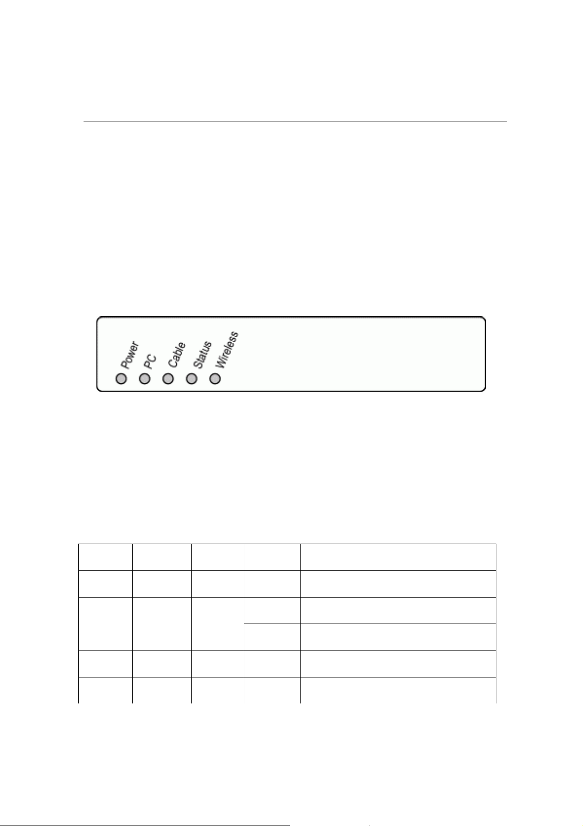
2.1.1 Front Panel Indicators
Figure 2-1: Front Panel LEDs
Four LEDs on the front panel (as figure 2-1) provide status indication of cable
modem operation. They are listed in the table below in order as viewed from
upper to under.
LEDs Function Color Active Description
POWER Power Green On Power is being applied to CM.
Green
Data
CABLE RF Data Green Blinking To indicate transmit RF US traffic.
STATUS Link Green On Modem registration completed.
On Ethernet/USB carrier is present.PC Link/PC
Blinking To indicate Ethernet or USB data.
4
Page 7

HARDWARE INSTALLATION
Blinking To indicate RF link status at different
speed.
1. Scan downstream channel. (2
sec cycle)
2. Downstream sync O.K and
receiving US parameters. (1 sec
cycle)
3. US ranging is O.K and receiving
IP and TFTP configuration.
(0.125 sec cycle)
4. Registration successfully. (Keep
On)
Green
Link/Data
On To indicate wireless link is present.Wireless Wireless
Blinking To indicate Wireless AP data.
2.1.2 Rear Panel Connectors
Figure 2-2: Rear Panel
5. If cable lost sync happens after
registration, cable LED will keep
blinking (2sec cycle) until it
recovers again.
5
Page 8

HARDWARE INSTALLATION
The connectors and switch on the rear panel from right to left are:
!
CABLE: F-Connector
!
USB: USB Connector
!
ETHERNET: Ethernet 10/100BaseT RJ-45 connector
!
RST: Reset-to-Default push button
!
12VDC: Power connector
2.2 Installation Procedure
This cable modem equips USB and Ethernet interfaces. You can choose
either one to connect to the cable modem. Go to Section 2.2.1, if your
computer has installed TCP/IP and Ethernet card with 10/100BaseT
capability. Go to Section 2.2.2, if your PC has USB port and the operating
system is Microsoft Windows 98/Me or Windows 2000/XP.
2.2.1 Installation Procedure for Ethernet Interface
Follow the following instructions for proper installation:
Step 1:Make sure your computer meets the system requirements in Section
1.2.
Step 2:Connect a coaxial cable (supplied by the local Cable Television
Company) to the CABLE connector on the modem.
NOTE: To speed up the initial cable modem registration process, the coaxial
cable should be connected to the modem prior to the power
connector.
Step 3:Connect the RJ45 Ethernet cable to the ETHERNET connector on the
modem, connect the other end with the 10/100BaseT Ethernet port
on your computer.
Step 4: Plug the power adapter into the POWER connector of the modem.
Step 5: Plug the other end of the power adapter into a power outlet.
6
Page 9

HARDWARE INSTALLATION
The cable modem will look for the proper cable modem signal in the Cable
Television network and process the initial registration. The cable modem is
ready for data transfer after the LED “STATUS” is in solid green.
NOTE: The RST button at the rear panel is for maintenance purpose only.
2.2.2 Installation Procedure for USB Interface
Follow the following instructions for proper installation:
Step 1:Make sure your computer meets the system requirements in Section
1.2.
Step 2:Connect a coaxial cable (supplied by the local Cable Television
Company) to the CABLE connector on the modem. NOTE: To speed
up the initial cable modem registration process, the coaxial cable
should be connected to the modem prior to the power connector.
Step 3: Connect the USB cable to the USB connector on the modem.
Step 4: Plug the power adapter into the POWER connector of the modem.
Step 5: Plug the other end of the power adapter into a power outlet.
The cable modem will look for the proper cable modem signa l in the Cable
Television network and process the initial registration. The cable modem is
ready for data transfer after the LED “STATUS” is in solid green.
NOTE: The RST button at the rear panel is for maintenance purpose only.
7
Page 10

HARDWARE INSTALLATION
2.2.3 Connecting the Cable Modem to Your Computer
8
Page 11
SOFTWARE INSTALLATION
3. SOFTWARE INSTALLATION
3.1 For Microsoft Windows 98/Me Users
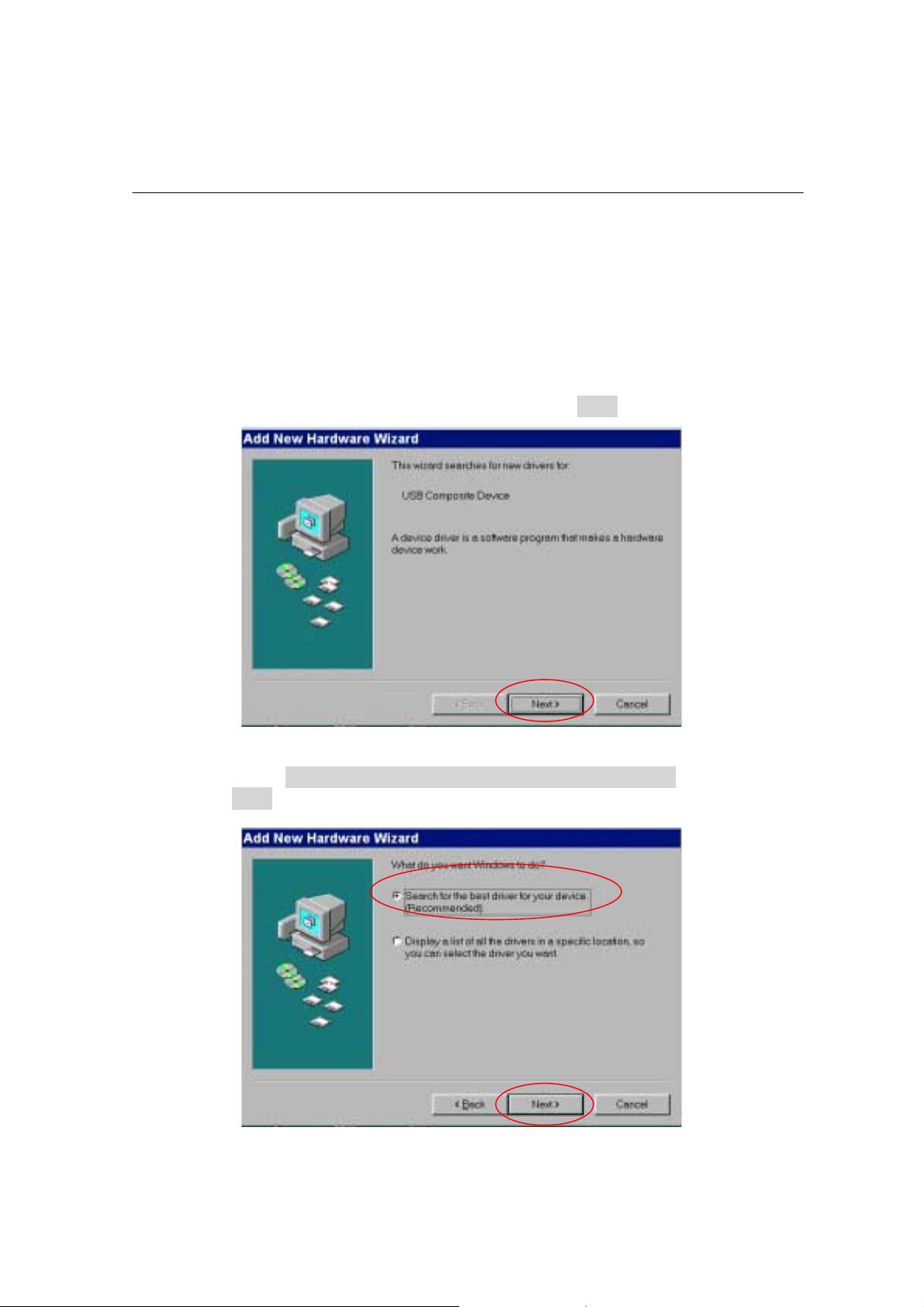
Steps 1:Wait for the cable modems is running in the operational state
(registration O.K.), and then plug the USB cable into your PC USB
port. You will see the next page. Click the “Next” button.
Step 2:Select “Search for the best drivers for your device“ and click the
“Next” button.
9
Page 12
SOFTWARE INSTALLATION
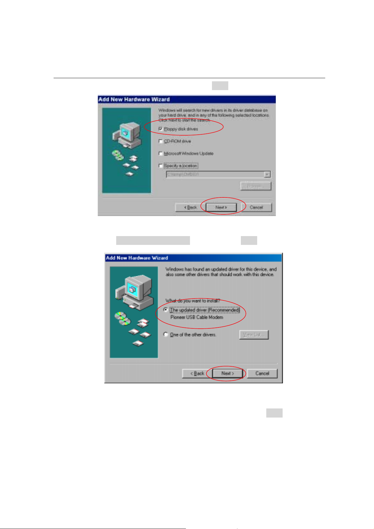
Step 3: Check Floppy disk drives. Click the “Next” button.
Step 4: Select “The updated driver...” and click the “Next” button.
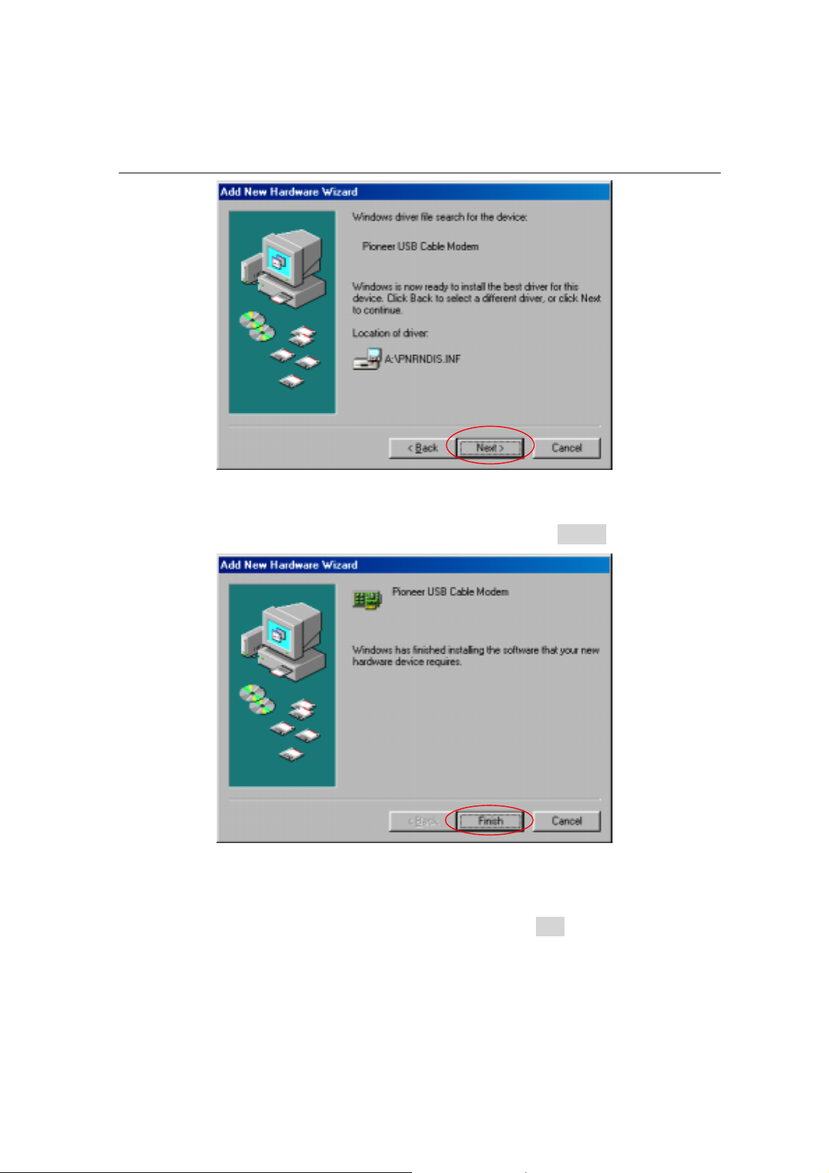
Step 5: Insert the driver disk into floppy drives A. Click the “Next” button.
10
Page 13
SOFTWARE INSTALLATION
Step 6: Installation has been completed here. Click the “Finish” button.
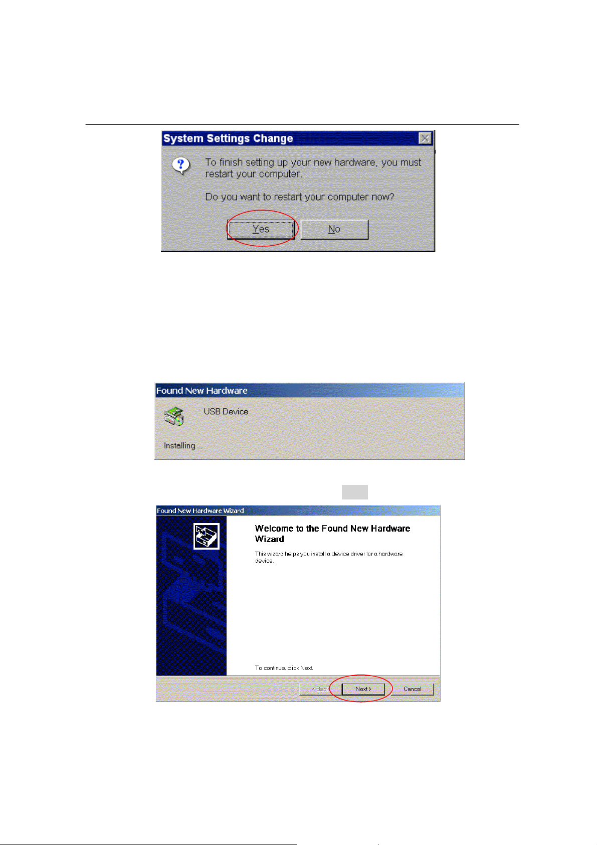
Step 7: The system will ask you to restart your computer. Remove the floppy
disk from the floppy drives and click “Yes” to complete the
installation.
11
Page 14
SOFTWARE INSTALLATION
3.2 For Microsoft Windows 2000/XP Users
Steps 1:Wait for the cable modems is running in the operational state
(registration O.K.), and then plug the USB cable into your PC USB
port.
Step 2:You will see the next page. Click the “Next” button.
12
Page 15
SOFTWARE INSTALLATION
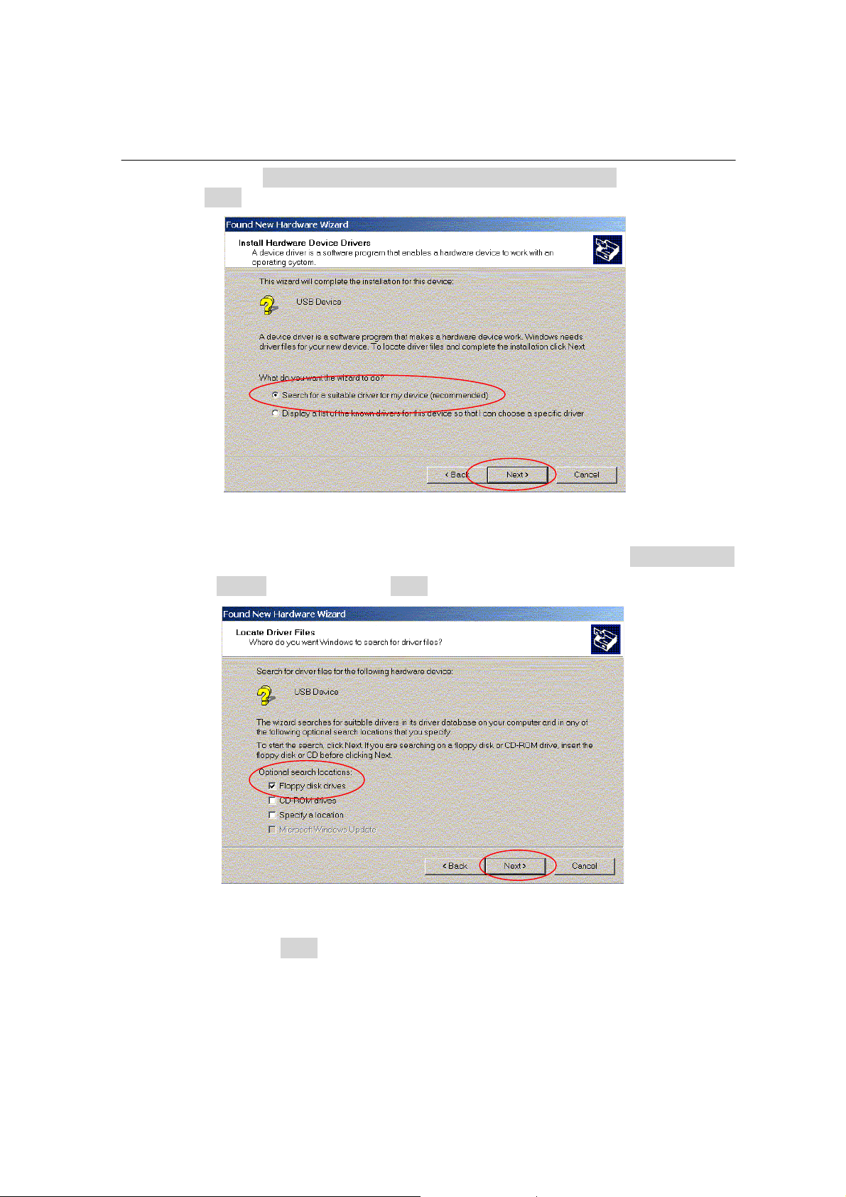
Step 3:Select “Search for a suitable driver for my device“ and click the
“Next” button.
Step 4: Insert the driver disk into floppy drives A. Select “Floppy disk
drives” and clicks the “Next” button.
Step 5: Click the “Next” button.
13
Page 16
SOFTWARE INSTALLATION
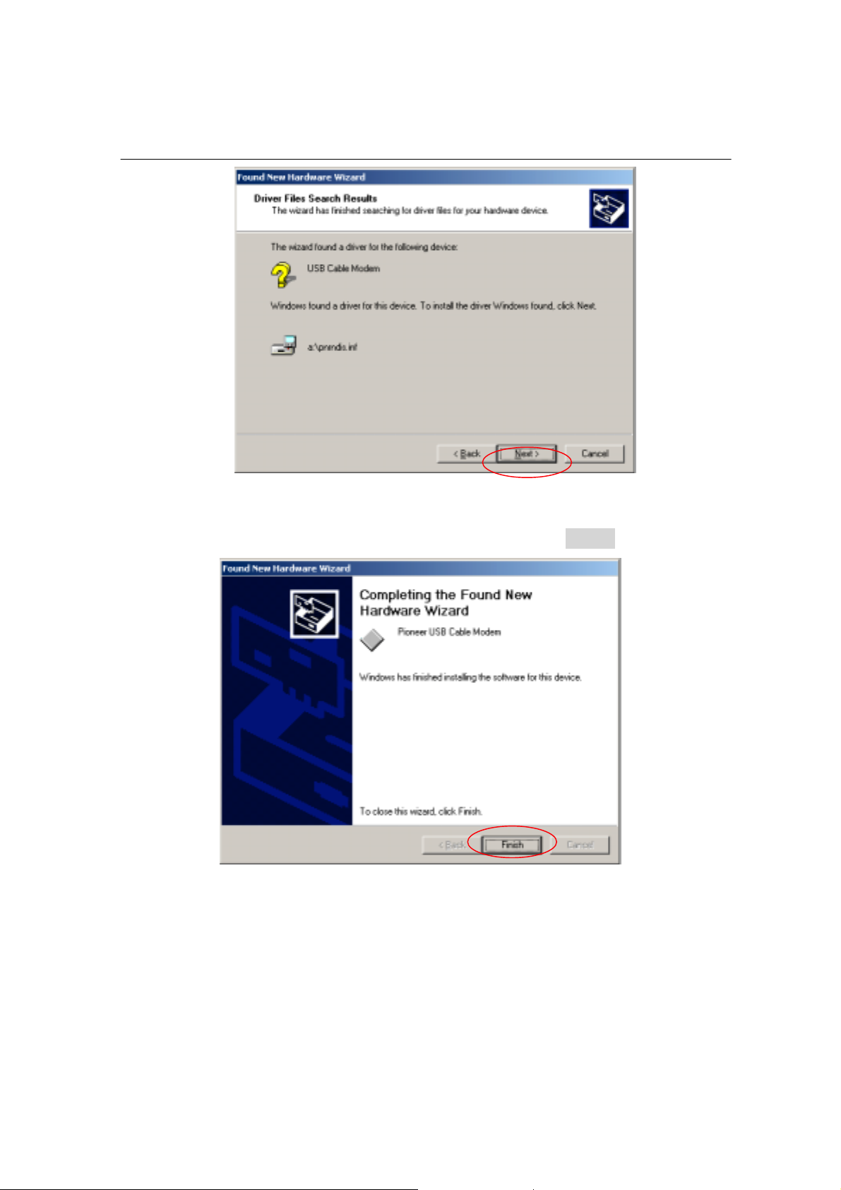
Step 6: Installation has been completed here. Click the “Finish” button.
3.3 Configuring the TCP/IP Protocol
After you successfully complete the network interface card (Ethernet card)
installation task, you need to make sure the TCP/IP communications
14
Page 17

SOFTWARE INSTALLATION
protocol used by the Ethernet card is installed and correctly configured on
your system.
3.3.1 Configuration on Windows 98/Me
Step 1:Click “Start” button on your computer’s taskbar, point to “Settings”,
and then click “Control Panel”.
Step 2: The Control Panel window will show up. Double-click the “Network”
icon in the Control Panel window.
15
Page 18

SOFTWARE INSTALLATION
Step 3: Windows will appear the Network dialog box. Click “Configuration”
tab to bring it to the front, and on this tab, a list of installed network
components appears. Look for an entry that includes TCP/IP->
followed by the Ethernet card installed in your computer.
If the entry is not present, click ”Add”.
16
Page 19

SOFTWARE INSTALLATION
Step 4:The Select Network Component Type dialog box will show up.
Click ”Protocol”, and then click ”Add”.
Step 5:You will see the Select Network Protocol dialog box. Click
“Microsoft” in the “Manufactures:” list, and then click “TCP/IP” in
the “Network Protocols:” list. Click “OK”.
17
Page 20

SOFTWARE INSTALLATION
You will be directed back to the Network dialog box, and on the
“Configuration” tab, the entry that includes TCP/IP -> followed by the
Ethernet card installed in your computer will appear in the list of installed
network components.
Step 6:Click TCP/IP -> followed by the Ethernet card installed in your
computer, and then click ”Properties”. The TCP/IP Properties
dialog box will appear.
18
Page 21

SOFTWARE INSTALLATION
Step 7:In the TCP/IP Properties dialog box, please follow the directions
below: Click “IP Address” tab to bring it to the front, and then click
“Obtain an IP address automatically” on the tab.
19
Page 22

SOFTWARE INSTALLATION
Step 8:Click “Gateway” tab to bring it to the front. On this tab, leave the
“New gateway:” blank. If there is the entry in the “Installed
gateway:” list, click it and then click “Remove” to remove all
installed gateways.
20
Page 23

SOFTWARE INSTALLATION
Step 9:Click “DNS Configuration” tabs to bring it to the front, and click
“Disable DNS”, then click “OK” to close the dialog box.
21
Page 24

SOFTWARE INSTALLATION
Step 10:The Copying Files dialog box will pop up and the system will start
copying files from Windows. At the first time you will be asked to
insert the Windows 98 CD-ROM (or diskette) into the CD-ROM
drive (or floppy diskette drive) during the files copying, and follow
the instructions when they show up, then click “OK”. You will be
prompted by another Copying Files dialog box. Please type the
command line that Windows 98/Me files located in the dialog box
(For example, D:\win98). Click “OK” to continue the files copying.
22
Page 25

SOFTWARE INSTALLATION
Step 11:Windows will appear the System Settings Change dialog box and
ask you if you would like to restart your computer. Click “Yes”.
3.3.2 Configuration on Windows 2000/XP
Step 1:Click “Start” button on your computer’s taskbar, point to “Settings”,
and then click ”Network and Dial-up Connections”.
Step 2:The Network and Dial-up Connections window will show up. Double-
click “Local Area Connection” icon in the Network and Dial-up
Connections window.
23
Page 26

SOFTWARE INSTALLATION
Step 3: The Local Area Connection status window will show up. Click the
“Properties” button.
Step 4:Click “Internet Protocol (TCP/IP)” and then click “Properties”.
24
Page 27

SOFTWARE INSTALLATION
Step 5:The Internet Protocol (TCP/IP) Properties dialog box appears. Click
“Obtain an IP address automatically”. Click “Obtain DNS server
address automatically”. Click “OK” to close the dialog box.
25
Page 28

SOFTWARE INSTALLATION
Step 6: Windows will appear the System Settings Change dialog box and
ask you if you would like to restart your computer. Click “Yes”.
26
Page 29

UNINSTALL THE USB DRIVER
4. UNINSTALL THE USB DRIVER
4.1 For Microsoft Windows 98/Me Users
Step 1:Click the “Start” button on your computer’s taskbar, point to
Settings”, and then click ”Control Panel”.
Step 2: The Control Panel window will show up. Double-click the
“Add/Remove Programs” icon in the Control Panel window.
27
Page 30

UNINSTALL THE USB DRIVER
Step 3: Select “USB Cable Modem Adapter”. Click the “Add/Remove”
button.
Step 4: Click the “Yes” button.
Step 5: Unplug the USB cable and click the “OK” button.
28
Page 31

UNINSTALL THE USB DRIVER
4.2 For Microsoft Windows 2000/XP Users
Step 1:Click the “Start” button on your computer’s taskbar, point to
Settings”, and then click ”Control Panel”.
Step 2: The Control Panel window will show up. Double-click the
“Add/Remove Programs” icon in the Control Panel window.
Step 3: Select “USB Cable Modem Adapter”. Click the “Change/Remove”
button.
29
Page 32

UNINSTALL THE USB DRIVER
Step 4: Click the “Yes” button.
Step 4: Unplug the USB cable and click the “OK” button.
30
Page 33

DHCP SERVER
5. DHCP SERVER
PC connected to the cable modem can automatically get a private IP
address from the DHCP server of cable modem before cable modem is on
line.
The following steps will show you how to get an IP address from DHCP
server of cable modem before cable modem is on line.
5.1 For Microsoft Windows 98/Me Users
Step 1: Click “Start“, point to “Run“, and click to open the “Run“ windows.
Step 2: Enter “winipcfg“ in the “Open“ field. Click “OK“ to execute the
winipcfg and show the “IP Configuration“ window.
31
Page 34

DHCP SERVER
Step 3: Select the “Ethernet adapter“ to show the IP address. Press
“Release“ and “Renew“ if the PC is not accessing the Internet. After
the cable modem is on line, you need to press the “Release“ and
“Renew“ to get a new IP address from your ISP’s server.
5.2 For Microsoft NT 4.0/Windows 2000/XP Users
Step 1: Click “Start“, point to “Run“, and click to open the “Run“ windows.
Step 2:The Run dialog box appears. Type “cmd” in the “Open” field, and
then click “OK” to execute the command.
32
Page 35

DHCP SERVER
Step 3: You will enter the dos mode , type “ipconfig”, press “Enter” on your
keyboard, and you will see the IP address your computer get from
the cable modem.
Step 4: If PC is not access Internet, type “ipconfig /release”, and press
“Enter” on your keyboard to release the IP.
33
Page 36

DHCP SERVER
Step 5:Type “ipconfig /renew”, and press “Enter” on your keyboard to
renew the IP. You can repeat the steps until your computer get the
correct IP.
5.3 For Apple Macintosh Users
Step 1: Click “Apple menu“, point to “Control Panels“, and click “TCP/IP”
to open the “TCP/IP” window.
34
Page 37

DHCP SERVER
Step 2:If the iMac get an invalid IP, select “Using DHCP Server” in
“Configure” field.
Click the “Close box” at the upper left corner to close the “TCP/IP”
window
Step 3: Click the “Save” in the prompted message box.
Step 4: You need to wait about 2 minutes and open “TCP/IP” window to see
the new TCP/IP status…
5.4 Renew PC IP Address
There is a chance that your PC does not renew its IP address after cable
modem is on line and the PC cannot access the Internet. Please follow the
procedures below to renew PC’s IP address after the cable modem is on
line.
Step 1: Click “Start“, point to “Run“, and click to open the “Run“ windows.
35
Page 38

DHCP SERVER
Step 2: Enter winipcfg in the “Open“ field. Click “OK“ to execute the winipcfg
and show the “IP Configuration“ window.
Step 3: Select the “Ethernet adapter“ to show the IP address. Press
“Release“ and “Renew“ to get a new IP address from your ISP’s
server.
Step 4: Select the “OK“ to close the IP Configuration window.
36
Page 39

6. WEB SERVER
6.1 System
This page shows the basic information about your cable modem. You can
get the H/W and S/W version of the cable modem. It also shows the
Ethernet MAC address of the cable modem.
WEB SERVER
6.2 Startup
This page provides information about the startup process of the cable
modem. You may check this connection sequence to know the current
status of your cable modem. It will display the current downstream
frequency the cable modem locks on.
37
Page 40

WEB SERVER
6.3 Signal
This page provides important information about the status and quality of
the communications between your cable modem and the cable modem
network.
38
Page 41

6.4 Status
This page provides important information about the operational status of
your cable modem and the devices that you have connected to it.
WEB SERVER
6.5 Log
This page provides important information that can be used to resolve
problems with your cable modem.
39
Page 42

WEB SERVER
6.6 Wireless
This page provides wireless connectivity within a range of several hundreds
feet and acts as a bridge between your wired LAN and wireless PCs. This
section shows you how to configure the wireless LAN setting.
Wireless SSID (Service Set Identity): A name that uniquely identifies a
wireless network. All clients that want to communicate with the Broadband
Wireless Router (AP) must have the same SSID as it.
Desired Channel: The frequency in which the radio links are about to be
established. Usually the clients will scan th e whole operable channels and
then select the desired communications channel automatically.
40
Page 43

WEB SERVER
6.7 WEP
The privacy security function can enhance media security by encryption technology. All
clients must set the same encryption key to maintain the tightened communication with
the Broadband Wireless Router (AP) properly. To turn on the privacy function:
Authentication Algorithm: Select Enable WEP as the authentication type.
Select Enable WEP: Open Key
If Open Key is selected as the authentication type, a wireless station can
associate to any wireless network available in the air and receive any
messages that are not encrypted.
Note: Open Key is also referred as Open System in some models.
Disable WEP: Shared Key
With shared key authentication, only those wireless stations that possess the
correct WEP keys can join the wireless network.
WEP Encryption
To enable WEP encryption function, select your encryption length as 64-Bit or 128-Bit.
When entering your WEP keys, notice that your WEP keys must be comprised of
hexadecimal characters (0-9, A-F, and a-f) and must contain 10 characters for 64-bit WEP
Keys or 26 characters for 128-bit WEP keys.
Default Tx Key: Select one WEP key from the four keys to encrypt the data you transmit.
41
Page 44

WEB SERVER
6.8 Operation
Setting the run mode, save configuration parameter and roboot.
Cable modem operation mo de default is router mode.
42
Page 45

6.9 LanIP
This page let the administrator to manage the private LAN interface.
WEB SERVER
6.10 NAT IP
This page shows NAT IP Address, NAT MAC Address and Subnet Mask.
The LAN configuration allows you to set the private IP address and
Subnet mask information of Ethernet side.
43
Page 46

WEB SERVER
6.11 DHCP Svr
This page let the administrator to manage the build in DHCP server in
Cable SOHO Gateway.
Dynamic Host Configuration Protocol (DHCP) dynam ically assigns p rivate
IP addresses within its local network. It can lease the IP addresses for a
user-defined amount of time.
In our DHCP server, we can provide the information with lease time,
domain name, client, DNS, and WINS server IP for local CPEs. We can
also reserve some specific IP for the use of internal servers.
44
Page 47

WEB SERVER
6.12 Mapping
The page provides the administrator to set up the virtual server in the
Cable SOHO Gateway. It provides the user of public network to access
the certain service (such as FTP, Web, Telnet by utilizing application view)
within private network.
It also provides the function of IP and Port redirection. For example, we
set up web server in internal server (IP: 192.168.100.5) and redirect the
web server from TCP/8080 port as follow i ng setting :
User defined port (8080) is virtual port.
IP (192.168.100.5) is internal server IP.
Port (80) is internal server port.
45
Page 48

WEB SERVER
6.13 Filter
The IP packet filters allow you to filter outbound packets that leave from
the Cable SOHO Gateway.
Basic Setting can let you do the filtering according to application
protocol types, such as HTTP, FTP, Telnet, SMTP, POP3, DNS, NNTP,
and RealAudio.
Advance Setting can be set to check packets according to the
combination of destination IP, netmask, port, and protocol type.
46
Page 49

WEB SERVER
6.14 SaveCFG
You can save configuration parameter to FLASH.
47
Page 50

FAQ
7. FAQ
Q1.Can I switch between a notebook and PC using the same cable
modem? Will there be a problem to obtain a DHCP IP address?
A. This issue depends on how your cable modem service provider manages
the modems. If you are using one of the cable modem service providers
that register your PC based on the MAC address of the Ethernet card in
the PC, then you will have to call them an d ha ve them chan ge tha t e nt ry
every time you switch between the two. Ask them if you have problem
on this issue.
Q2.Can I use the same cable line for TV and cable modem?
A. Yes, the TV and cable modem uses the cable line. You need a splitter to
use them at the same time. Ask Cable Company to install the splitter for
you to avoid signal degradation.
Q3. My cable modem cannot get a solid green light on the Status LED
when I connect the cable back.
A. The cable modem lost the signal during the disconnection period and it
will keeps scanning other available signal. When you connect the cable
back, it might take a while to find the correct channel. You can power
cycle the modem to speedup the p rocess since modem will remember
the channel last time and it will start from that channel at startup.
Q4. Which port of the Ethernet hub should I connect to the modem if I
need to connect multiple PC to the modem?
A. You should connect the modem to the up-link port of the hub. The link
LED of the hub will be on.
Q5. How do I see my IP address?
A. If you are using Windows 95/98 /Me, the winipcfg comman d will show you
to IP address of the PC connected to the cable modem. Notice that even
though you seem get the same address all the time, it may still be a
dynamic address.
Q6. Can I just connect the cable modem and two computers to a hub?
A. Yes. You need to make sure you can get two IP addresses from your
cable modem service provider. Connect the modem to the up-link port of
the hub.
48
Page 51

FAQ
Q7. I have a cable modem. How can I make it work?
A. Basically, modem is plug and play. You can just connect the modem and
you are ready to go if you have the subscription. For ensure good signal
for your cable modem, you should ask your cable provider to install the
cable modem for you.
FCC Caution
1. The device complies with Part 15 of the FCC rules. Operation is subject to
the following two conditions:
(1)This device may not cause harmful interference.
(2)This device must accept any interference received,
including interference that may cause undesired operation.
2. FCC RF Radiation Exposure Statement: The equipment complies with
FCC RF radiation exposure limits set forth for an uncontrolled
environment. This equipment should be installed and operated with a
minimum distance of 20 centimeters between the radiator and your body.
3. This Transmitter must not be co-located or operating in conjunction with
any other antenna or transmitter.
4. Changes or modifications to this unit not expressly approved by the party
responsible for compliance could void the user authority to operate the
equipment.
49
 Loading...