

Page 1
USER MANUAL LDB 2
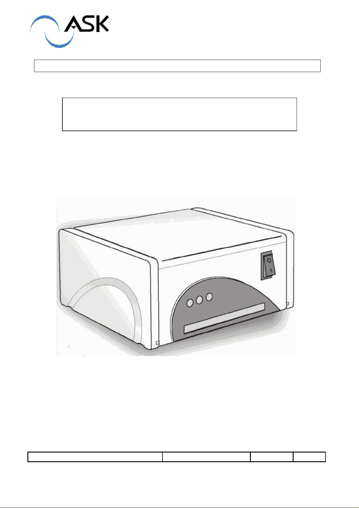
ASK LDB 2 DESKTOP READER
ASK R&D Réf. : RD-ST-03022-10 Rév.: 1.0
ASK
5 traverse des Brucs. Les Bouillides R&D001-Form1
06560 VALBONNE SOPHIA ANTIPOLIS
Tel : 04 97 21 40 00
Fax : 04 92 38 93 21
1 / 10
Page 2

FCC Compliance Statements
This equipment has been tested and found to comply with the radiated limits for a Class B
digital device, pursuant to Part 15 of the FCC Rules. These limits are designed to provide a
reasonable protection against harmful interferences in a residential installation. This
equipment generates, uses and can radiate radio frequency energy and, if not installed and
used in accordance with the instructions, may cause harmful interference to radio
communications. However, there is no guarantee that interference will not occur in a particular
installation. If this equipment does cause harmful interference to radio or television reception,
which can be determined by turning the equipment off and on, the user is encouraged to try
the correct interference by one or more of the following measures:
- Reorient or relocate the receiving antenna.
- Increase the separation between the equipment and receiver.
- Connect the equipment into an outlet on a circuit different from that to which the
receiver is connected.
- Consult the dealer or an experienced radio/TV technician for help.
This device complies with Part 15 of the FCC rules. Operation is subject to the following two
conditions. (1) This device may not cause harmful interferences. And (2) this device must
accept any interference received, including interference that may cause undesired operation.
The ASK LDB 2 reader was submitted and a grand of authorization received from the FCC as
device under the intentional radiator requirements of Part 15, Subpart C.
The party that incorporates this device into their product is responsible for verification of the
emissions produced by the final product and must adhere to the limits specified in the Code of
Federal Regulation 47, Part 15, subpart B.
Compliance accessories: The accessories associated with this equipment are: shielded
serial cable with ferrite tube and linear sector adaptor (12V DC 500mA). These accessories
are required to be used in order to ensure compliance with the FFC rules.
Caution: Any changes or modification not approved by ASK could void user’s authority to
operate the equipment. Switching power mode adaptors are prohibited.
CE Compliance statement
The ASK LDB 2 reader is in conformity with European requirements, this product has been
assessed to the following standard:
EN 300 330
EN 301 489-3
EN 50121-4
EN 60950-1
ASK R&D Réf. : RD-ST-03022-10 Rév.: 1.0
ASK
5 traverse des Brucs. Les Bouillides R&D001-Form1
06560 VALBONNE SOPHIA ANTIPOLIS
Tel : 04 97 21 40 00
Fax : 04 92 38 93 21
2 / 10
Page 3

TABLE OF CONTENTS
1 SCOPE OF MANUAL 4
1.1 UNPACKING AND INSPECTION 4
2 LDB 2 READER 4
2.1 READER COMPONENTS 5
2.1.1 Coupler board 5
2.1.2 Antenna board 6
2.1.3 Power supply board 6
2.1.4 Contact card interface board 7
2.2 Assembly 7
3 READER SETUP 8
3.1 INSTALLING A NEW SAM IN READER 8
3.2 READER CONNEXION 9
4 HOW TO USE THE READER 10
4.1 CONTACTLESS OPERATIONS 10
4.2 CONTACT OPERATIONS 10
4.3 SOFTWARE 10
4.4 CLEANING 10
ASK R&D Réf. : RD-ST-03022-10 Rév.: 1.0
ASK
5 traverse des Brucs. Les Bouillides R&D001-Form1
06560 VALBONNE SOPHIA ANTIPOLIS
Tel : 04 97 21 40 00
Fax : 04 92 38 93 21
3 / 10
Page 4
USER MANUEL LDB 2
DESKTOP READER
1 SCOPE OF MANUAL
This manual describes ASK LDB 2 reader main features and setup information. This manual
is intended for use by end users. No specific tools are required for operation described in this
document.
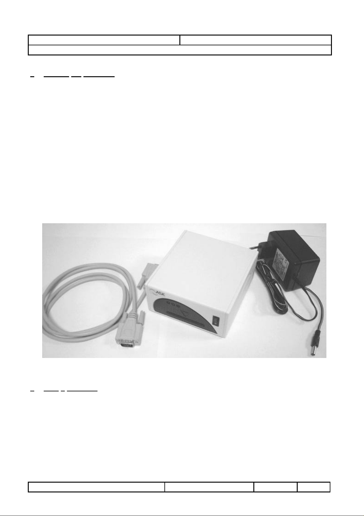
1.1 UNPACKING AND INSPECTION
Each LDB 2 kit is shipped with :
- serial cable (length : 3 meters)
- This user manual
- One power supply 110V AC / 12V DC 500mA
- LDB 2 reader packaged in plastic case
2 LDB 2 READER
LDB 2 readers are contactless readers designed for integrators and operators as
development tools as well as desktop readers for card issuing center and point of sales.
LDB 2 provides the communication between a terminal and customer smart cards.
ASK R&D Réf. : RD-MU-03036-10 Rév.: 1.0
Copyright ASK SA - 2003
4 / 10
Page 5

USER MANUEL LDB 2
Figure 3 : GEN 320 board
DESKTOP READER
2.1 READER COMPONENTS
LDB 2 consists of a control board called ”coupler board”, and antenna board, a DC supply
converter board (with two extra SAM sockets) and a contact card interface board.
2.1.1 COUPLER BOARD
The coupler board contains a microprocessor, non-volatile memory and a radio frequency
transmitting circuitry. This board communicates with smart cards via RF link (provided by an
antenna board), and to the terminal via RS-232 interface. The serial rate is set to 115,2 bps.
The coupler platforms are GEN320 or GEN325 elements which can be purchased separately
at ASK. These two OEM coupler boards are compliant with ISO/IEC14443-2 directives (Radio
frequency power and signal interface). Communications can be executed according to the
type A or type B of the directive.
TOP VIEW
Antenna connector
RS232 connector
SAM location
Figure 1 : GEN 320-GEN 325 board
GEN 320 and GEN 325 board are strictly identical, except that on GEN 325, PHILIPS ‘s
RC500 chip is added. In this case, the chip just manages MIFARE cryptography mode.
The RC500 chip is located (or not) at the bottom of the printed circuit board (PCB).
BOTTOM VIEW
Figure 2 : GEN 325 board
ASK R&D Réf. : RD-MU-03036-10 Rév.: 1.0
Copyright ASK SA - 2003
RC500 chip
5 / 10
Page 6

USER MANUEL LDB 2
DESKTOP READER
2.1.2 ANTENNA BOARD
The antenna board consists of a printed circuit board with copper traces forming the transmit
and the receive antenna. Antenna may be one of several types, varying in dimensions and
connection. LDB 2 receives GEN 530 antenna because its area (110x120mm) matches well
with a desktop application. This antenna has a tuning capacitor, but no setting is required
because it has been optimized in factory.
Figure 4 : LDB 2 antenna board : GEN 530
2.1.3 POWER SUPPLY BOARD
This board contains a DC-DC converter and two extra SAM locations. Input line should be
from 9V to 36V DC. Typically an AC power bloc with output 12V 500mA (without regulation)
should be used.
SAM location
Figure 5 : LDB 2 DC conversion / SAM extension board : GEN 351
ASK R&D Réf. : RD-MU-03036-10 Rév.: 1.0
Copyright ASK SA - 2003
6 / 10
Page 7

USER MANUEL LDB 2
DESKTOP READER
2.1.4 CONTACT CARD INTERFACE BOARD
This card has been added for allowing standard contact card transactions.
Contact card connector
Figure 6 : LDB 2 contact card interface board : GEN 362
2.2 ASSEMBLY
Inside the plastic case these boards are stacked together (Figure 7). This way, no cables are
needed :
Contact card interface board
Power supply board
coupler board
Antenna board
Figure 7 : stacked boards in reader
ASK R&D Réf. : RD-MU-03036-10 Rév.: 1.0
Copyright ASK SA - 2003
7 / 10
Page 8

USER MANUEL LDB 2
DESKTOP READER
3 READER SETUP
3.1 INSTALLING A NEW SAM IN READER
In most applications, one SAM (Security Application Module) or more is required.
These components are provided separately, so to set a SAM, the plastic case
should be opened.
For opening, flip over the plastic case. You have to put a blade in the rear slot and
lift the bottom of the case in order to set free a central ergot. Then the bottom of the
box should be removed by sliding in the front side direction.
The stacked board will appear as in Figure 7, the first SAM should be installed on
coupler board GEN 32X (Figure 1) and next SAMs should be installed on DC
conversion board GEN 351 (Figure 5).
Caution : In a first time, µSIM SAMs must be gently inserted in the open door
socket (Figure 8), then in a second time the door should be locked.
SAM
Figure 8 : SAM in open door
ASK R&D Réf. : RD-MU-03036-10 Rév.: 1.0
Copyright ASK SA - 2003
8 / 10
Page 9

USER MANUEL LDB 2
DESKTOP READER
3.2 READER CONNEXION
The reader’s DB9 should be connected to a RS232 serial port, usually to a
computer via the serial cable provided.
Plug the main adapter included in the « Power-Jack » connector. The main adapter
should provide 12V DC – 500mA.
Turn on the switch located at the front side, the red LED will light at power-on. The
LDB 2 is then in power and ready to work.
Serial connector
To computer
Power jack
Figure 9 : LDB 2 connexions
ASK R&D Réf. : RD-MU-03036-10 Rév.: 1.0
Copyright ASK SA - 2003
9 / 10
Page 10

USER MANUEL LDB 2
DESKTOP READER
4 HOW TO USE THE READER
4.1 CONTACTLESS OPERATIONS
All the top surface of LDB 2 reader is active. Contactless smart card must be laid flat on the
reader, yellow LED is turned on when operation is correct.
4.2 CONTACT OPERATIONS
The smart card should be inserted, chip on top, in the front slot of the LDB 2 reader (card
contact faces triangle on reader front side).
The card should be pushed until a resistance appears (reader’s contacts fall down on card’s
contact).
4.3 SOFTWARE
The LDB is delivered by default with an application software called CSC which supports the
ASK cards and C.ticket families.
The external LEDs of the reader can be controlled by customer applicative software using
CSC software commands.
In the same way, the GEN360 contact card reader and the extra SAM modules supported by
the GEN351 board have to be managed by the host application via CSC protocol.
4.4 CLEANING
No adjustments on the reader are required. To clean, simply wipe with a wet cloth and plastic
cleaner, abrasive products are prohibited.
ASK R&D Réf. : RD-MU-03036-10 Rév.: 1.0
Copyright ASK SA - 2003
10 / 10
 Loading...