

Page 1

QUICK SET UP
SVGA DLP PROJECTOR
ENGLISH
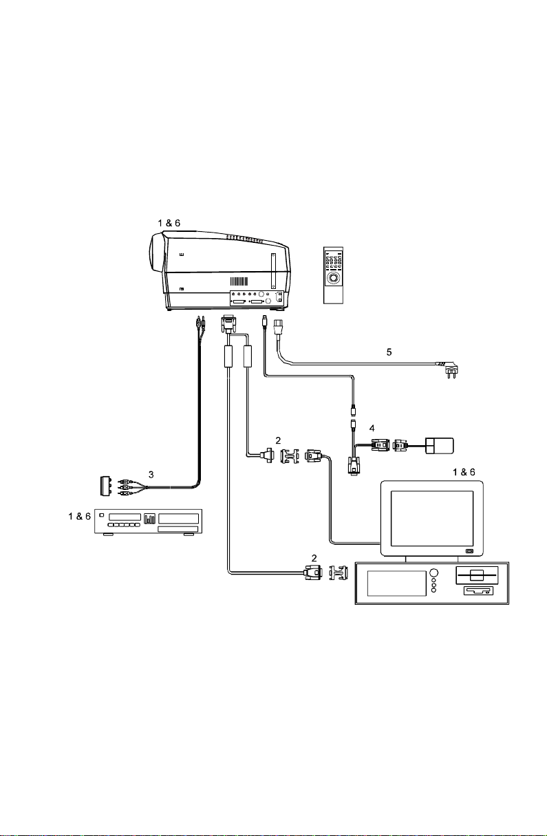
SETTING UP
POWER OFF (1)
Switch off all equipment before
connecting.
COMPUTER (2)
Connect the computer to the
COMPUTER input using the SVGA
cable and applicable computer and
monitor adapters if needed.
VIDEO (3)
Connect video, using the AV cable,
to the VIDEO and SOUND inputs.
Use a SCART adapter if
necessary.
MOUSE (4)
Connect the mouse cable to the
MOUSE connector of the projector.
Use an applicable mouse adapter
at the computer end.
MAINS (5)
Connect the power cords to the
various equipment.
POWER ON (6)
First switch on the projector, then
the source equipment to facilitate
correct recognition of the projector
as a peripheral unit to the
computer.
USE
ZOOM , FOCUS AND POSITION
Zoom the lens for image size desired,
focus the lens for an optically sharp
image and tilt the unit using the
integral adjustable feet to position the
image on screen.
WIDTH
Invoke the menu and select SETUP,
then FREQUENCY. Use a patterned
background and adjust until the
pattern is stable all over the screen.
STABILITY
In SETUP, select TUNE to stabilize
the image.
SCALING
If desired, press the SCALE button to
fit the image to the full screen.
POSITION
In SETUP, select POSITION to fit the
image within the screen borders.
CONTRAST AND BRIGHTNESS
Adjust CONTRAST and
BRIGHTNESS as preferred.
COLOR , TINT AND SHARPNESS
In the menu, select PICTURE, then
adjust COLOR, TINT (NTSC only)
and SHARPNESS as desired.
Page 2
Page 3

USER GUIDE SVGA DLP PROJECTOR
TABLE OF CONTENTS
1 SYMBOL DESCRIPTIONS....................................................................5
2 SAFETY INSTRUCTIONS.....................................................................6
3 INTRODUCTION ...................................................................................9
4 MAIN FEATURES ...............................................................................10
5 SUPPLIED MATERIAL........................................................................11
5.1 STANDARD MATERIAL......................................................11
5.2 OPTIONAL MATERIAL.......................................................11
6 MAKING THE CONNECTIONS ...........................................................12
7 IMAGE ADJUSTMENTS......................................................................15
8 USING THE PROJECTOR..................................................................17
8.1 REMOTE CONTROL ..........................................................17
8.2 PROJECTOR KEYBOARD..................................................20
8.3 THE MENU SYSTEM..........................................................21
8.3.1 THE SET-UP MENU SELECTIONS ....................22
8.3.2 THE PICTURE SELECTIONS (VIDEO
ONLY).........................................................................22
8.3.3 THE SOUND SELECTIONS................................23
8.3.4 THE OPTIONS SELECTIONS ............................23
8.3.5 THE HELP SELECTIONS...................................24
9 CEILING MOUNTING..........................................................................25
9.1 SELECTING A MOUNT.......................................................25
9.2 MOUNTING IN THE CEILING.............................................25
9.3 WIRING..............................................................................26
10 YOUR PROJECTOR IN DETAIL........................................................27
10.1 SLB - SMALL, LIGHT AND BRIGHT..................................28
10.2 DMD TECHNOLOGY........................................................28
10.3 DLP OPTICAL SYSTEM....................................................28
10.4 TRACKBALL REMOTE CONTROL....................................28
10.5 MENU SYSTEM................................................................29
10.6 OSD SYSTEM ..................................................................29
10.7 SET-UP MEMORY............................................................29
10.8 COOLING SYSTEM..........................................................29
10.9 MONOCHROME MODE....................................................30
11 APPLICATIONS................................................................................31
11.1 PORTABLE USE...............................................................31
11.2 WORK GROUPS..............................................................31
11.3 TEACHING.......................................................................31
11.4 TRAINING ........................................................................32
11.5 HOME THEATRES ...........................................................32
11.6 CONTROL ROOMS..........................................................32
11.7 PRODUCT PROMOTION..................................................32
3
Page 4

USER GUIDE SVGA DLP PROJECTOR
11.8 TRADE SHOWS...............................................................33
11.9 SIMULATORS...................................................................33
12 TROUBLE-SHOOTING .....................................................................34
13 MAINTENANCE ................................................................................36
13.1 GENERAL.........................................................................36
13.2 LAMP REPLACEMENT.....................................................37
13.3 THE REMOTE CONTROL.................................................38
14 TECHNICAL DATA ............................................................................ 39
14.1 GENERAL ENVIRONMENTAL LIMITS..............................39
14.2 PROJECTOR UNIT...........................................................40
14.3 POWER SUPPLY.............................................................41
14.4 REMOTE CONTROL ........................................................41
14.5 COMPATIBILITY...............................................................41
14.6 PROJECTION DISTANCES..............................................42
15 CONNECTORS.................................................................................43
15.1 COMP 1 AND COMP 2 .....................................................43
15.2 MOUSE ............................................................................44
15.3 S-VIDEO...........................................................................44
15.4 VIDEO..............................................................................44
15.5 AUDIO..............................................................................44
16 ENVIRONMENTAL HANDLING.........................................................45
17 FCC STATEMENT.............................................................................46
This publication is printed on recycled paper
The information contained in this User Guide is preliminary, and the
products described herein are subjected to change without prior notice.
4
Page 5

USER GUIDE SVGA DLP PROJECTOR
1 SYMBOL DESCRIPTIONS
DANGEROUS VOLTAGE
This symbol indicates the presence of high voltages inside
the product. High voltages may constitute electric shock
and may be lethal.
WARNING
This symbol alerts the user of important operating,
maintenance (servicing) and safety-related instructions.
HOT
This symbol indicates hot surfaces, i.e. fan ventilation grill.
NOTE
This symbol is used to highlight specific information for the
user.
5
Page 6

USER GUIDE SVGA DLP PROJECTOR
2 SAFETY INSTRUCTIONS
The following list of instructions is provided to ensure safe and risk free use
and operation of the projector. Failing to read and follow these instructions
may void any warranties and may also cause personal injury and material
damage.
1. READ INSTRUCTIONS. All safety and operating instructions should be
read before the projector is operated.
2. RETAIN INSTRUCTIONS. The safety and operating instructions should
be retained for future reference.
3. HEED WARNINGS. All warnings on the projector and in the User Guide
should be adhered to. If ignored, use of this projector may cause death,
injury or material damage.
4. CABLES AND CORDS. Use only original cables and cords as supplied
with the projector or as optional accessories. Using third party cables
that may look identical may lead to material damage and personal
injury, as the internal wiring in the cables may be different.
5. LAMP LIFE. See the Technical Data section for lamp life time. The
high pressure lamp may explode if improperly used. When the lamp life
time is exceeded, the projector will fail to turn on the lamp, and a red
indicator (ALARM) on the projector will light up. Change lamp with
an identical spare part as described elsewhere in this User Guide.
6. LAMP BEAM. Do not look directly into the projector or lens when
operating the projector. The lamp emits rays of strong light which may
cause eye injury and/or sunburns.
7. WATER AND MOISTURE. The projector is designed for indoor use
only and should not be used near water and moisture.
8. CARTS AND STANDS. Place the projector on a stable, hard surface in
a manner that does not obstruct ventilation ports and openings in the
projector housing. Unstable carts, stands, tables and other
arrangements may cause the projector to fall, which may cause serious
injury to people and/or damaging the projector and other material.
6
Page 7

USER GUIDE SVGA DLP PROJECTOR
9. CEILING MOUNTING. When mounting the projector in the ceiling,
always ensure that all screws, bolts and other fixing devices of the
ceiling mount hardware are securely in place and tighten. Use only well
dimensioned ceiling mounts specified for this projector and from a
renowned supplier. Connect the projector to a switched mains power
supply, and switch off when not in use, for maximum protection against
fire. Switching off using the remote control only puts the projector in a
standby (sleep) mode with live internal voltages.
10. VENTILATION. Slots and openings in the projector housing are
provided for ventilation. Periodically vacuum the air inlets (from the
outside of the ventilation grilles) as needed. To ensure reliable
operation of the projector and protection from overheating, do not block
or cover slots or openings in any way. Do not insert any foreign objects
or instruments into the slots and openings, as this may block the
ventilation fans. Do not place the projector on a soft surface (carpet
etc.). Never install the projector in an enclosed unit unless it is properly
ventilated by a separate cooling system.
11. HEAT. The projector should be situated away from heat sources such
as sunlight, radiators, stoves or other strong heat sources. Do not
operate the projector outside the maximum temperature specifications.
12. OBJECT OR LIQUID ENTRY. Care should be taken so that objects are
not put or do not fall into the projector housing. Be careful not to spill
liquids that may flow into the projector interior. Do not insert metal or
flammable objects into the projector.
13. POWER SOURCES. The projector must only be connected to proper
electrical voltage as marked on the projector body, on the label at the
power inlet. The projector should be connected to the electrical outlet
using a power cord compatible with the local electrical voltage. Never
operate the projector outside the electrical voltage specification. If you
are unsure about the type of electrical service at your location, please
consult your dealer or local power company.
14. POWER CORD PROTECTION. Power cords should be routed so that
they are not likely to be walked on, pinched or unduly bent by items
placed upon or against them. Pay particular attention to cords and
cables at the point where they exit from the projector.
7
Page 8

USER GUIDE SVGA DLP PROJECTOR
15. GROUNDING OR POLARIZATION. Precautions should be taken so
that grounding or polarization of the projector is maintained. Do not use
a three prong to a two prong adapter.
16. ELECTRICAL SHOCK. To reduce the risk of electrical shock, do not
open the unit. Refer all servicing to authorized personnel only.
17. CLEANING. The projector should be cleaned only as recommended,
see the Maintenance section. Disconnect the power cord from the
power outlet before cleaning. Do not use liquid, spray or aerosol
cleaners.
18. NON-USE PERIODS. The power cord of the projector should be
unplugged from the outlet when left unused for a long period of time.
19. LAMP REPLACEMENT. Replace projection lamp with same type and
rating as shown in the Technical Data section. Allow unit to cool down
before replacement.
20. SERVICING. The user should not attempt to perform unusual or
technical service to the projector. Do not open the unit, except for the
lamp replacement door. Refer all servicing to authorized personnel
only. Replace damaged cords or cables with original replacement parts
only.
21. DAMAGE REQUIRING SERVICE. The projector should be serviced by
authorized personnel when:
• objects have fallen, or liquid spilled, into the projector
• the projector has been exposed to water or moisture
• the projector does not appear to operate normally (fan not
working, noise, smell, smoke, heat etc.)
• the projector has been dropped or damaged
22. ABNORMALITY. If you detect any abnormal smell or smoke,
immediately turn off the power switch. Disconnect the power plug from
the inlet to prevent fire or electrical shock.
23. LIFTING AND MOVING. Let the projector cool down before moving.
Disconnect the power cord and all other cables. Carry the unit by the
handle provided. The projector should preferably be transported in a
suitable case.
8
Page 9
USER GUIDE SVGA DLP PROJECTOR
3 INTRODUCTION
Thank you for purchasing this state of the art SVGA full color projector!
For long and lasting, safe and secure operation, please read this user
guide, and follow the instructions given. Failing to do so may cause product
failure that could void any warranties given, and in some cases be harmful
and dangerous to people.
For the experienced user, a quick set-up guide is included at the beginning
of this manual.
Please retain this user guide for future reference.
All references to video/video interface/video connections made
in this document, only applies to the multimedia version of the
SVGA DLP Projector.
9
Page 10

USER GUIDE SVGA DLP PROJECTOR
4 MAIN FEATURES
The unit employs the following important features that in total provide you
with a highly functional and powerful projector:
• High brightness image
• Compact, light and portable
• User replaceable Metal Halide lamp
• True SVGA 800 x 600 resolution
• 640 x 480 to 1152 x 870 image compatibility
• 16.7 million colors
• Stereo sound
• Infrared remote control with trackball mouse
• Motorized Zoom and Focus lens
• Comprehensive menu system
• On screen display (OSD)
• User and source settings memorized
• Low noise cooling system
• False light blocking
10
Page 11
USER GUIDE SVGA DLP PROJECTOR
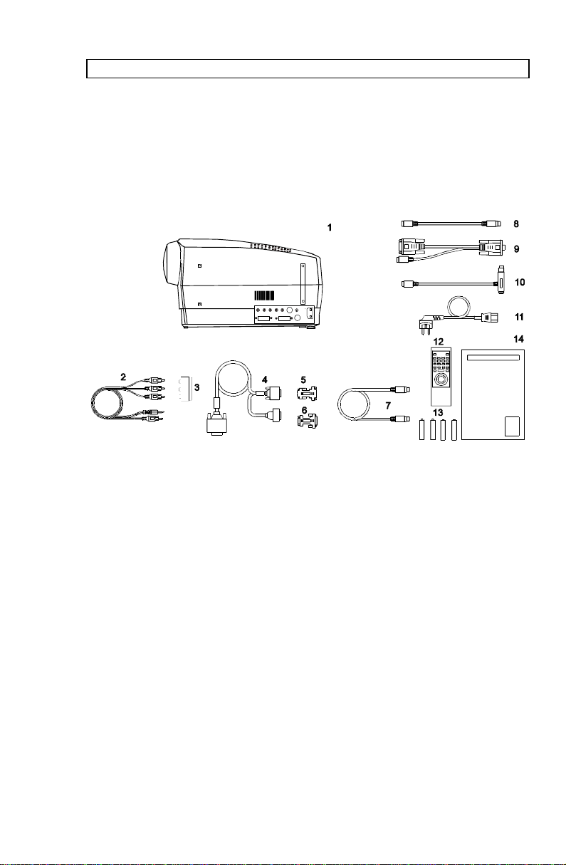
5 SUPPLIED MATERIAL
5.1 STANDARD MATERIAL
A complete set includes the following components :
1. LCD projector* 8. Mouse Adapter PS/2
2. A/V cable** 9. PC Adapter Y-Split (serial,RS232)
3. SCART Adapter** 10. MAC Mouse Adapter
4. SVGA Y-Split Cable 11. Power Cord
5. MAC computer adapter 12. Remote Control
6. MAC monitor adapter 13. Batteries
7. Mouse Cable 14. User Guide
* Soft Case (not shown in drawing) ** Multimedia version only
5.2 OPTIONAL MATERIAL
Optional cables, adapters and accessories are available. Consult your
dealer for further information.
11
Page 12

USER GUIDE SVGA DLP PROJECTOR
6 MAKING THE CONNECTIONS
The projector may be connected in various ways to different equipment.
The following sections describe in detail how to connect to these systems.
See the illustration on the rear of the quick set-up card on how the various
system parts connect together.
Be aware of static electricity that may build up in the dry season and when
operating on synthetic carpets. Discharge any static electricity by touching
a metallic surface before you start.
Place the projector on a table at a suitable distance to the projection
screen. Select a screen with good reflectivity and avoid direct sunlight
shining in. Place the projector so that the image is visible to the whole
audience, and so that the unit does not obstruct the view. The projector is
supplied with long cables for high flexibility in placement.
Various cables are supplied or optionally available to connect to different
sources. Follow the list below in numerical order for a trouble-free set-up!
1. SWITCH OFF. Switch off all equipment before making all the
connections.
2. COMPUTER GRAPHICS ADAPTER. Computer graphics adapters use
different connectors depending on the actual computer system in use.
Connection to the projector is made through a basic SVGA cable and
appropriate adapters.
• PC. Use the SVGA cable directly to connect the graphics port
of the PC to the COMPUTER connector on the projector. If
needed, connect your monitor cable to the free branch on the
SVGA cable.
• MAC. Use the MAC adapters, as marked, on the computer end
of the SVGA cable to adapt to the graphics-port connector and
monitor connector on the MAC.
• NEC. Use the optional NEC adapters, as marked, on the
computer end of the SVGA cable to adapt to the graphics-port
connector and monitor connector on the NEC.
12
Page 13

USER GUIDE SVGA DLP PROJECTOR
3. VIDEO. Video connects through different interfaces, depending on the
type of equipment and quality level of the video signal.
• COMPOSITE VIDEO. This is the most frequently used video
connection. Use the AV cable (supplied) to connect between
the yellow phono (also known as ‘RCA’ or ‘cinch’) connector on
the video source and the yellow VIDEO input connector on the
projector.
The AV cable also provides connection to stereo sound. The
stereo jack connects to the AUDIO input connector on the
projector and the red and white phono connectors on the video
source.
• SUPER VIDEO. Use the optionally available S-VIDEO cable to
connect to the video source. S-VIDEO may give a better
quality image than composite video.
Use the AV cable for sound connection as described above.
• SCART ADAPTER. Some video sources are provided with the
SCART adapter for video and audio output. The SCART
adapter (supplied) provides connection to the AV cable.
• RGB VIDEO. Some high end video sources have component
red, green and blue video outputs for a best possible image.
Some systems use BNC type connectors, other systems use
the older CGA or the VGA connector. Contact your dealer for
an adapter that is suitable for your source. Use the AV cable
for stereo sound connection.
4. MOUSE. To enable mouse control from the remote control, a
connection is made using a mouse cable and various adapters.
Connect the cable directly to the MOUSE connector on the projector.
Connect the appropriate adapter to the free end of the mouse cable at
the computer end as described below.
• SERIAL (RS 232). Use the serial PC adapter with a Y-split
branch for the local computer mouse. The serial adapter is
fitted with a 9 pin DSUB connector. Use an extra 9 to 25 pin
adapter (available from your dealer) if your computer has a 25
pin serial connector. Connect your computer mouse to the free
branch of the adapter if desired. With some computers, the
13
Page 14

USER GUIDE SVGA DLP PROJECTOR
branched adapter may not work. For this purpose, an optional
straight serial adapter is available.
• PS/2. Use the PS/2 adapter that connects directly to your
computer mouse port. Running the computer mouse in parallel
is not possible, unless your computer itself has provision for
two mice simultaneously. You may consider using the above
serial adapter and run your mouse on the serial port instead to
be able to run your local mouse in parallel. This will require a
different mouse driver setting. Please consult your computer
documentation or local dealer for details.
• MAC. Use the MAC mouse adapter to connect to the mouse
port on your MAC computer.
5. MAINS POWER. Connect the mains cord to the projector and all other
equipment in the set-up.
6. SWITCH ON. Switch on the projector first, then the computer and video
sources. It is important to switch the projector on first in order for
correct detection of the projector as a display and mouse peripheral
device to the computer.
14
Page 15
USER GUIDE SVGA DLP PROJECTOR
7 IMAGE ADJUSTMENTS
This section will aid in adjusting a stable, flicker-free image for best
viewing results.
Use the remote control or the projector keypad to adjust settings, either
directly or through the menu system.
The following list aids in a trouble free set-up of the projector. Try using a
patterned background (tiles, checkerboard pattern etc) when adjusting the
image.
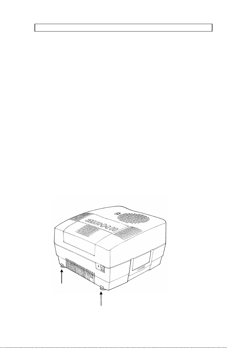
1. ZOOM, FOCUS AND POSITION IMAGE. The projection lens has a
motorized zoom and focus adjustment. The controls are directly
accessible on the projector keyboard or on the remote control by
invoking the menu system, SET-UP, ZOOM or FOCUS and press
ENTER. Place the projector at a suitable distance to the projection
screen, alternatively zoom the image, to obtain the desired screen size.
(See the Technical Data section for max and min projection distances.)
Focus the image and observe that the picture elements (pixels) become
sharp on screen. The projector has two adjustable feet so that the
image can be shifted to a desired height on the wall. Tilt the projector
body in the desired position and press the foot-release buttons. If
necessary, fine adjust the height by screwing the feet either direction.
Adjustable feet
15
Page 16

USER GUIDE SVGA DLP PROJECTOR
2. SET FREQUENCY. The frequency controls the width of the image. A
wrong frequency setting can be seen as equally spaced, vertical stripes
or irregularities in the pattern displayed. Invoke the menu system, SETUP, FREQUENCY and press ENTER. Adjust the value up or down
using the trackball or keyboard cursor controls, observing that the
amount of vertical stripes reduces, until the distortion is gone. You may
still have an unstable image, please see the next section.
3. TUNE. Tune the image for a stable projection. In the menu, select SET-
UP, TUNE and press ENTER. Adjust stability using the trackball.
4. SCALE & PAN . Scale the image as desired if you are viewing a lower
(VGA) or higher (XGA) resolution image. Scaling will fill the viewable
area by enlarging a lower resolution or compressing a higher resolution
image. If you do not scale a higher resolution image, you may choose
to PAN around instead in order to view parts of the image.
5. POSITION. Position the image correctly by accessing SET-UP,
POSITION, then press ENTER and adjust position with the trackball or
keyboard cursor controls
6. CONTRAST and BRIGHTNESS. Contrast and brightness may be
adjusted according to your personal taste, the image and the viewing
conditions. The controls are directly accessible on the remote control
and on the projector keyboard.
7. COLOR, SHARPNESS and TINT. These adjustments may be made
when viewing video images from the VIDEO or S-VIDEO inputs. These
controls do not apply to computer images.
Set-up should be done once with the source(s) you are using most
frequently. Allow some minutes for the unit to warm up before adjusting the
settings. Most settings will be memorized individually for each source for
future use.
16
Page 17

USER GUIDE SVGA DLP PROJECTOR
8 USING THE PROJECTOR
The projector has a set of features and functions you should familiarize
with in order to get the most out of using the unit.
Further information is provided in the Your Projector in Detail section.
8.1 REMOTE CONTROL
The remote control is used to adjust the projector for the best possible
image, either directly or through the menu system. It is also used during
presentations for computer mouse control and with special presentation
tools.
The remote control may be pointed directly at the projector
front or rear, where the receivers are situated, or indirectly by
pointing at the projection screen. When pointing at the screen,
point at an angle that reflects the beam towards the projector.
The trackball is by default controlling the computer mouse (if the mouse
cable is connected properly). With some functions, like POINTER, MASK
and in the menu system, the mouse control is disabled.
17
TRACKERBALL
PLATE
LEFT KEY
(ENTER)
RESET
CONTR
COMP 1
MASK
BRIGHT
COMP 2
LIGHTPOINTER
VOLUME
VIDEO
PAN
BOTTOM KEY
ON/OFF
MUTE
FREEZE
S-VIDEO
PROGSCALE
MENU
RIGHT KEY
TRACKERBALL
Page 18

USER GUIDE SVGA DLP PROJECTOR
In the menu system, the trackball is used for navigation between the
different alternatives, and when a function is selected, the trackball is used
for adjustment of that function.
The following table describes each key in detail. Some functions are
memorized, while other functions are only momentary.
The MEM column indicates whether the function setting is memorized for
the source apparatus for future use.
KEY FUNCTION MEM
CONTR Contrast is the ratio between light and dark
Yes
colors. Low contrast is recommended for longterm viewing, while high contrast is used to
enhance details.
BRIGHT Brightness (whiteness) of the image can be
Yes
altered to suit local lighting conditions. Usually
a bright, low contrast image is preferred.
VOLUME Volume of the audio output can be altered to
Yes
suit local conditions.
ON/OFF Turns the projector into standby mode.
Switches the projection lamp off, but leaves
power on to the rest of the projector.
RESET Defaults to the standard settings for the active
mode.
COMP 1 Selects the computer 1 as the active source. COMP 2 Selects the computer 2 as the active source. VIDEO Selects video as the active source. S-VIDEO Selects S-video as the active source. MASK Applies a mask to the image, which can be
moved up and down using the trackball.
PROG This key may be programmed to any one of the
Yes
menu controls.
MUTE Switches the sound on/off. No
FREEZE Holds the image projected on the screen. This
No
feature can be used to hide actions on the
computer that the audience need not see, such
as changes between software packages, or for
returning the audience’s attention back to the
presenter!
18
Page 19

USER GUIDE SVGA DLP PROJECTOR
KEY FUNCTION MEM
POINTER Applies a trackball controlled pointer to the
screen.
SCALE Selects between direct 1:1 mapping or scaling
of images.
PAN Allows panning within oversized images using
the trackball.
TRACKBALL The trackball is mainly used to control the
mouse pointer (if the mouse cable is attached
properly). When SCALE, MASK, PAN or MENU
is invoked, mouse control is disabled, as the
trackball is used to control these functions
instead. Trackball sensitivity, except for the
mouse, is set under OPTIONS in the menu
system. Mouse sensitivity is set at your
computer as with the standard mouse.
RIGHT Emulates the right mouse key. DRAG This emulates the ‘click-and-hold’ function of
the desktop mouse.
Use DRAG instead of RIGHT key when
connected to a Macintosh computer.
LEFT/
ENTER
Emulates the left mouse key.
Once the menu is accessed selection are
confirmed using ENTER.
No
No
-
-
-
-
19
Page 20

USER GUIDE SVGA DLP PROJECTOR
8.2 PROJECTOR KEYBOARD
The keypad on the projector gives access to all controls, either directly or
through the menu system.
ALARM
ON/OFF
RESET
CONTRAST
BRIGHT
VOLUME
MENU
SOURCE
CURSORS
ENTER
ZOOM
FOCUS
The following table describes each key in detail. For details on CONTR,
BRIGHT, VOLUME & MENU see the remote control section above.
KEY FUNCTION MEM
ZOOM Zoom is used to obtain the desired screen size
of the image.
FOCUS Focus is adjusted until the image (pixels)
becomes sharp on the screen.
SOURCE Toggles between computer 1, computer 2,
S-video and video as the active source
CURSOR
KEYS
The cursor keys are used to navigate in the
menu system
ENTER Emulates the left mouse key.
Once the menu is accessed selection are
confirmed using ENTER.
-
-
-
-
-
20
Page 21

USER GUIDE SVGA DLP PROJECTOR
INDICATOR FUNCTION
ON/OFF
ALARM
• NO LIGHT indicates that the unit is completely
switched off by the mains switch
• GREEN indicates that the unit is operational
• YELLOW indicates that the unit is in standby mode
(switched off using the remote control or the keypad)
• RED indicates lamp lifetime overdue.
8.3 THE MENU SYSTEM
The menu system is designed to gain access to functions not often used,
as opposed to frequently used features that are directly available through
the remote control and the projector keypad.
Press the MENU key to invoke or exit from the menu system. When the
menu is active, the trackball is used to navigate between options (and
therefore is not available for mouse control etc. at the same time). The
ENTER (left) key is used to activate or deactivate a function.
The PROG key may be assigned to any of the menu functions.
Toggle functions (like OSD, REAR etc) are tagged when active and
untagged when not active.
Increase/decrease functions (like TUNE and FREQUENCY etc) are
adjusted using the trackball or keyboard cursor controls. The OSD field (in
the lower left corner of the screen) indicates the actual settings.
The menu system is toggled on and off with the MENU key. The MENU is
also switched off automatically after one minute of inactivity.
Most settings are memorized unless otherwise noted.
The main menu selections SETUP, PICTURE, SOUND, OPTIONS and
HELP are explained in detail below.
Features available with some sources only are shown in Italic characters,
while generally available functions are in normal case.
21
Page 22

USER GUIDE SVGA DLP PROJECTOR
8.3.1 THE SET-UP MENU SELECTIONS
ZOOM is used to obtain the desired screen size of the image at a given
projection distance.
FOCUS is adjusted until the image (pixels) becomes sharp on the screen.
TUNE is used to stabilize the image. An untuned image can be seen as
sideways instability or “swimming”. The TUNE function has no effect in
VIDEO mode.
FREQUENCY is provided in order to image width. Generally, an incorrect
frequency setting can be observed as an image too wide or too narrow,
combined with vertical, unstable bands.
POSITION. Due to minor variations in graphic cards, the horizontal and
vertical position may need adjustment. Select POSITION, then press LEFT
and use the cursor keys.
REAR inverts the image for use in rear projection arrangements i.e.
projection from the back of a screen.
CEILING switches between an upright and an upside-down projection by
flipping the image vertically.
FACTORY RESET. This function resumes factory settings of all
parameters.
8.3.2 THE PICTURE SELECTIONS (VIDEO ONLY)
TINT controls the hue of an image, and is only active in NTSC-video.
SHARPNESS controls the sharpness of the lines in an image, and is only
active for video sources.
COLOR adjusts color saturation. Only applicable when video is connected.
GAMMA toggles the gamma correction on and off for video sources. Only
active for video sources.
22
Page 23

USER GUIDE SVGA DLP PROJECTOR
8.3.3 THE SOUND SELECTIONS
TREBLE controls the higher sound range.
BASS controls the lower sound range .
BALANCE controls the sound balance between the two stereo speakers.
MONO must be selected if the audio source is not stereo, in order to get
sound in both speakers.
8.3.4 THE OPTIONS SELECTIONS
HIDE OSD switches the on-screen echoing of controls on and off. This
setting only affects the direct control operations, not the menu system. This
setting is not memorized.
SOURCE SEARCH is a toggle function that controls whether the projector
shall automatically search for an active source or not. Manual source
selection is maintained between active sources. Source priority is
COMPUTER 1, COMPUTER 2, S-VIDEO and then VIDEO. If SOURCE
SEARCH is off (not tagged), the manually selected source is maintained,
regardless of signal presence. If SOURCE SEARCH is active, the projector
will switch to the next priority active source, regardless of manual selection.
TRACKBALL SENSITIVITY. Controls the response of the remote control
trackball in the menu system. (It does not affect the response of the
computer mouse. Please adjust mouse sensitivity on the computer). FAST,
MEDIUM and SLOW are available options.
LANGUAGE. A selection of languages is available for the menu options,
including English, German, French, Italian, Spanish, Norwegian and
Japanese. Other languages may apply.
POINTER selects the pointer appearance. Options include BALL, ARROW
and CROSS. Other shapes may apply.
MASK selects whether the mask is applied downwards or upwards.
SERVICE is used for resetting the lamp timer. This is done when the lamp
is changed.
23
Page 24

USER GUIDE SVGA DLP PROJECTOR
8.3.5 THE HELP SELECTIONS
SOURCE INFO provides a status list of parameters relating to the source
selected.
ABOUT provides system information about the projector. It shows TOTAL
TIME that the projector has been used since it was manufactured, LAMP
LIFE TIME USED and SOFTWARE REVISION.
24
Page 25

USER GUIDE SVGA DLP PROJECTOR
9 CEILING MOUNTING
The projector is prepared for ceiling mounting. As opposed to desktop use
(most tables are approx. 80 cm tall, are flat and have a hard surface
finish), ceilings vary in height and material. Also considerations must be
made with respect to signal and power wiring.
9.1 SELECTING A MOUNT
Various mounting systems are available from different sources. Contact
your dealer for further details or consult vendor catalogs.
Be sure that the vendor has tested the mount with this specific
projector for operational safety.
Check that the mounting brackets fit the integral M4 screw mounts
(threaded inserts) of the projector, and that the ventilation slots are not
blocked.
Avoid using screws that penetrates more than 5 mm into the
screw mounts, and do not overtighten the screws as this
may cause damage to internal parts of the projector.
9.2 MOUNTING IN THE CEILING
An improperly mounted projector is a potential danger to
people and equipment. A projector and mount falling down
may cause personal injury and material damage. Such
damage caused by bad workmanship in mounting and
operation may lead to legal action and should be avoided.
Avoid ceiling mounting of the projector in areas of frequent or
probable earth quakes.
When fixing the mount in the ceiling, be sure to check the ceiling material
and if it will hold the total weight of the mount and the projector. Look for
wood, steel beams or concrete that will secure a good and lasting fixture.
Avoid plaster or other fragile materials that do not have sufficient structural
properties. Follow the detailed instructions supplied with the ceiling mount
for proper mounting and operation.
25
Page 26

USER GUIDE SVGA DLP PROJECTOR
After having mounted the projector in the ceiling, test if the holding force is
sufficient by adding a load to the mount double the weight of the combined
projector and mount. The mount should hold this extra weight with no sign
of fatigue and with no sign of mounting screws loosening.
9.3 WIRING
Ceiling mounted projectors require long signal and power wires.
The signals should be wired using high quality coaxial cable. The cables
usually need to be customized. Some vendors have specialized in this field.
Contact your dealer for further detail.
If the signal cables run over a longer distance from the source to the
projector, a line buffer (distribution amplifier) may be needed (available
from third party vendors).
For potential fire reasons, the power wiring should be
separately switched so that the projector can be switched off
completely when not in use. The ON/OFF on the remote
control only suspends operation of the projector without
switching off completely.
26
Page 27

USER GUIDE SVGA DLP PROJECTOR
10 YOUR PROJECTOR IN DETAIL
The projector is designed from the ground up to be a compact, durable,
bright and versatile device that is suitable for use in various indoors
projection applications.
International mandatory regulations are employed, including the rigorous
European CE and American UL and FCC standards that cover safety and
radio interference issues.
Product packaging is by environmentally friendly materials that are
recyclable and that do not emit any toxic fumes if combusted. The ‘RESY’
and ‘Grüne Punkt’ marks are referenced (with ID numbers), indicating that
the proper fees are already paid for controlled return of packaging material.
To allow for flexible operation and installation, the unit may be operated
from the tabletop, ceiling mounted or in a rear-projection arrangement.
Safe thermal operation is secured through a temperature controlled, well
dimensioned cooling system that is minimizing fan noise and stray light.
Compatibility is wide, including most popular computer sources from VGA
(640x480 expanded) to XGA (1024x768 compressed) resolution as well as
all international video standards (NTSC, PAL and SECAM) and video
formats (composite video, super video and RGB video).
A wide mains voltage operating range is employed, and connection is
through the internationally recognized IEC connector. The user guide and
menu system are multi-lingual.
The following chapters detail various features of your projector that may be
of interest.
27
Page 28

USER GUIDE SVGA DLP PROJECTOR
10.1 SLB - SMALL, LIGHT AND BRIGHT
The projector was designed to be the ultimate portable projector.
The advanced, miniaturized optical design and the use of a relatively low
power, high efficiency illumination system combined with optimalized
electronics has yielded a very compact, lightweight projector.
10.2 DMD TECHNOLOGY
The light valve technology employed in the projector is based on a small
Digital Micromirror Device (DMD). The DMD is basically an integrated
circuit chip covered with a large number of minute mirrors, one for each
picture element (pixel). These tiny mirrors may be actuated digitally by
electrostatic force individually at high speed. This enables the formation of
a full color gamut of 16.7 million colors perceived by the eye. It is actually
the eye that ‘integrates’ the digitally generated full color image into what is
perceived as a continuous (analog) set of colors.
10.3 DLP OPTICAL SYSTEM
The DMD chip is part of the Digital Light Processing (DLP), which is the
complete optical system from illumination lamp all the way to projection
lens that enables the projection of high quality, digital images.
In the DLP, the light from the illumination lamp is directed onto the DMD.
Light is then reflected off each mirror through a rotating color wheel that
sequences between red, green and blue in order to form a full color image.
The image is then projected by the projection lens onto the screen.
The projection lens has motorized zoom and focus control available to the
user in order to be able to select a suitable magnification (image size) at a
given projection distance, and to adjust for a sharp image.
10.4 TRACKBALL REMOTE CONTROL
This device enables both set-up of the projector before use and control
both of the projector and the computer mouse pointer during operation.
The mouse functionality duplicates the local computer mouse without the
need for any special software drivers.
28
Page 29

USER GUIDE SVGA DLP PROJECTOR
10.5 MENU SYSTEM
The menu system is designed so that it may be invoked and overlayed at
any time with any image projected. When invoked, the menu system will
not interrupt the display of the underlying image. The hierarchical design,
with a main menu and sub-menus, provides a logical approach to access
the various functions. The localization in the upper left corner and the
moderate size of the menus does not block much of the view of the image
displayed. Several languages are selectable to suit international users.
10.6 OSD SYSTEM
The OSD (On Screen Display) is used to echo user controls for positive
feedback. The OSD is active both within the menu and with direct controls.
The OSD should not be confused with the menu system, the latter being
used to gain access to controls, while the OSD merely indicates the actual
operation. The OSD may be selected or deselected in the menu.
10.7 SET-UP MEMORY
The various user selections and settings that are made with the remote
control, the projector keypad and the menu system, are automatically
memorized for future reference. Most settings are related to the actual
source in use, so when switching between sources, or between modes
within sources, the individual settings are recalled accordingly.
The memory can store up to 40 different sources and mode characteristics.
Some sources are predefined, while the remaining are available for
customer set-up. See the compatibility list in the Technical Data section.
New sources are added to the memory only if the sync pattern differs
significantly from a previous selection. If a new source is detected as an
old one (close or identical sync patterns), and the settings are changed, the
new settings will override the old ones.
See the Remote Control and Menu sections for details of which functions
that are memorized.
10.8 COOLING SYSTEM
The heat generated in the projection lamp and the electronics circuitry
needs to be effectively vented out of the projector. Cooling fans are
employed to force the convection of air through the system. Air is let out
close to the projection lamp (as this is the hottest area).
29
Page 30

USER GUIDE SVGA DLP PROJECTOR
The projector is designed to operate at a wide temperature range and
works well when ceiling mounted, even at high ambient temperatures. See
the Technical Data section for temperature specification.
The cooling system is temperature controlled, so that when operated on the
desktop at normal temperature, the noise level is minimized due to a
relaxed fan speed. When operating in the ceiling under high ambient
temperatures, the fan runs at a higher speed to maintain cooling while the
noise level increases. The light leakage out of the vents is minimized by a
special light blocking design of the vent flanges.
10.9 MONOCHROME MODE
In some presentations where colors are not required, i.e. word processing
documents or spreadsheets, the monochrome mode can be used to
increase the brightness.
Monochrome button
When the monochrome button (black & white) is pulled up the brightness is
increased three times compared to color mode. To return to color mode,
press button down.
30
Page 31

USER GUIDE SVGA DLP PROJECTOR
11 APPLICATIONS
The projector is perfectly suited for a variety of different applications
including portable use, work groups, teaching, training, home theatres,
control rooms, product promotion, shows, simulators and more.
11.1 PORTABLE USE
The projector is designed with portability in mind for the nomadic user. The
footprint is small and the weight is low. The unit is supplied with a soft
carrying case holding the projector and all cables. The unit can be carried
on-board an aeroplane and fits easily in the overhead locker. Remember
that the projector is a delicate instrument containing precision optics. Avoid
bumping and dropping the unit during transportation. When checking the
unit in at the airport, ensure proper packaging to avoid breakage and
malfunction. It is wise to bring an extra projection lamp, just in case.
11.2 WORK GROUPS
A work group typically involves a group of people actively involved in
discussions round the table. The projector usually is connected to a
networked computer. As the meeting evolves, various documents are
continuously updated and corrected. Information is downloaded from the
Internet or the company Intranet for up-to-date processing in the group.
Video may be played back any time with high quality stereo sound. By the
end of the session, the documents are wrapped up and minutes are
distributed to the various recipients over the e-mail system. The projector
may be placed on a table or permanently installed, either ceiling mounted
or arranged for rear projection.
11.3 TEACHING
Educational institutions would use the projector both for traditional
computer and video based teaching for the class, as well as interactive use
over the Internet. By using the projector, the attention of the students is
focused on a single large projection screen, supplementing the ordinary,
individual computer monitors when needed. The projector may be placed
on a table or permanently installed, either ceiling mounted or arranged for
rear projection.
31
Page 32

USER GUIDE SVGA DLP PROJECTOR
11.4 TRAINING
The projector is ideally suited for company training in various areas such
as products, software, organisational and staff continued education. It is
practical for this purpose to have a dedicated training room with good
facilities for each individual in order to secure the attention of each person
during the training session. It may sometimes help to break up the session
with a video to regain any lost attention! The projector may be placed on a
table or permanently installed, either ceiling mounted or arranged for rear
projection.
11.5 HOME THEATRES
The projector is equipped with multistandard composite and super-video,
as well as stereo sound, enabling large screen projection of high quality
video. The user has full control over all parameters including color,
sharpness contrast and brightness through the remote control and the
menu system for the best possible projected image.
11.6 CONTROL ROOMS
Large screen projection of critical information enables a quicker and more
consistent reaction to any change that needs immediate attention. This
includes both manufacturing process control, as well as operational control
in private, public and military situations. Several projectors may be
cascaded or grouped to simultaneously project over a larger area or to
project different screens simultaneously, using a dedicated screen splitter
(available from third party suppliers). These applications are typically fixed
and the projectors are usually either ceiling mounted for front projection or
arranged in a rear-projection set-up.
11.7 PRODUCT PROMOTION
The projector is ideally suited to attract attention in order to promote sales
of all kinds of products in shops and malls. The promotion material may be
either computer generated or video based. Several projectors may be
employed simultaneously to increase attention further. The projector is
usually semi-permanently installed, either ceiling mounted or arranged for
rear projection.
32
Page 33

USER GUIDE SVGA DLP PROJECTOR
11.8 TRADE SHOWS
Many companies attend various trade shows throughout the year. In these
situations, the key issue is to attract the attention of a large, continuously
moving public. One or more units projecting your company message will
help steering the crowd to your business. The projector might be either
placed on the table top, ceiling mounted or used for rear projection. Since
control over lighting conditions is difficult at trade shows, arranging two
projectors on top of each other projecting, the same image on the same
screen will help by increasing the brightness.
11.9 SIMULATORS
Simulators are used in various applications for training and entertainment.
Professional use includes car driving, air plane and ship vessel control
training, as well as other expensive and often dangerous situations that
require well trained personnel. Entertainment use is basically in various
theme parks etc.
33
Page 34

USER GUIDE SVGA DLP PROJECTOR
12 TROUBLE-SHOOTING
This is a checklist to help you pinpoint any problem that may arise. Check
the symptoms carefully if you experience any problem. The cure may be at
your fingertips!
Always check that the ON/OFF indicator on the projector
flashes when the a key on the remote control is pressed.
This indicates that the projector is receiving signals from the
remote control.
SYMPTOM SOLUTION
The projector
does not work
The projected
image is
completely
black
The projected
image is
completely
black, but the
fans are running
The projected
image is too
dark or too light.
Some colors are
unstable or
flickering
• Check if the mains cable is attached properly.
• Check that the Power switch is ON.
• Toggle the ON/OFF button on the remote control.
• Check that the Power switch at the mains inlet is
ON.
• The unit may have overheated due to the
ventilation slots being covered while the projector
was in use. Also ensure that the ambient
temperature is within spec. Check the air inlet, as
it may need vacuuming. Wait until the unit has
completely cooled down before using again.
• The lamp may have burned out and needs to be
changed. If the red alarm LED is lit, see the Lamp
Replacement section for details.
• Adjust the CONTRAST and BRIGHTNESS
settings.
• Press RESET, which will remove the predetermined settings for the current source, and
make the set-up adjustments again.
• Check first that there are no loose cable
connections.
• You can try to adjust the image quality with the
CONTRAST and BRIGHTNESS keys.
Try to improve the tuning by accessing TUNE in
the menu system.
See the Image Adjustment section for details.
34
Page 35

USER GUIDE SVGA DLP PROJECTOR
SYMPTOM SOLUTION
The whole
image appears
to be unstable
or misplaced
• If the image is scaled, press SCALE to return to
the default mode.
• Adjust the frequency and tuning settings
(instability), or the image position settings
(misalignment).
• Check that you are using a source with
compatible resolution.
• The projector may be connected to a source with
a non-standard computer (or video card). Adjust
the frequency and position of the image.
See the Image Adjustment section for details
Cooling fan is
not working
• Check that the Power ON/OFF switch is ON.
• If the fan does not work the projector must not
be used and should be returned to your dealer
for repair.
The remote
control is not
working
• Check the batteries by pressing LIGHT on the
remote control. The keypad shall then be
backlighted by a red light.
• Check that the green LED on the projector is
blinking when you press any one of the keys on
the remote control.
• Make sure you point the remote control at the
projection screen or directly at the IR receiver
• The maximum range of the IR transmitters is
15m (50 feet) - Are you standing close enough?
• If the effective range of the transmitters is
significantly reduced, the remote control needs
new batteries.
The desktop
mouse is not
working
• Remember that the mouse must be connected,
and the projector switched on, before the
computer source is switched on.
• Are the mouse cable and mouse adapter
connections secure?
• Check the mouse driver settings on the computer
• You must boot the computer after the cable has
been connected for it to recognise the mouse. If
you are unsure whether this was the case, reboot
your computer.
35
Page 36

USER GUIDE SVGA DLP PROJECTOR
13 MAINTENANCE
The projector needs very little maintenance in order to function properly.
13.1 GENERAL
Use a damp cloth to wipe off dust on the exterior. Clean the lens with a
damp, non-abrasive cloth, using just water or a standard lens cleaning
solution available from photographic dealers.
Vacuum the air inlets periodically, especially when build-up of dust is
observed. This will ensure cool operation of the unit.
Do not scratch the lens surface. Use the lens cap when the projector is not
in use for added protection. Remember to remove the lens cap before
operating the unit!
36
Page 37

USER GUIDE SVGA DLP PROJECTOR
LAMP HOUSE HANDLE
13.2 LAMP REPLACEMENT
The projector is using a custom metal halide lamp for illumination. The
lamp is high pressure when hot (operating or immediately after switch-off).
Lamp pressure is normal when cold.
A lamp timer is available in the menu system under HELP, ABOUT, that
may be used to track lamp operating time. The timer may be reset by the
user.
To change lamp, remove the lamp lid by unscrewing the three screws
indicated below. A safety switch will cut off the power supply to the lamp
completely.
Lamp lid screws
Twist the handle on the small screw to unlock the lamp holder. Fold out the
large handle and pull out the lamp holder.
LOCK
37
Page 38

USER GUIDE SVGA DLP PROJECTOR
Insert a new lamp. Push the lamp holder all the way until it positively stops.
Twist the handle on the small screw to lock the lamp holder. Fold the large
handle and remount the lamp lid. Mount all the screws holding the lamp lid
tightly.
Use only original lamp and holder as specified. The lamp is
individually adjusted with the holder to maintain optimum
illumination. Replacement using a different lamp may result
in poor illumination, malfunction (potentially explosion) and
will void any warranties.
To reset the lamp timer, invoke the menu system under OPTIONS,
SERVICE, LAMP TIMER RESET. You need to confirm that you actually
intend to reset the lamp timer, or cancel if you accidentally invoked the
function.
13.3 THE REMOTE CONTROL
The infrared remote control requires little maintenance.
The trackball element may be cleaned occasionally with a damp (not wet)
cloth. To take out the ball, twist the ring holding the ball anti-clockwise.
Having taken out the ball, you may also clean the trackball interior using a
damp (not wet) cotton swab.
To change the batteries, open the battery holder on the rear of the handset.
Remove the old batteries and dispose of carefully. Insert new batteries of
the type described in the Technical Data section, observing the polarity
instructions inside the battery holder, and close the clip-shut door. Test that
the remote control functions correctly by pressing the LIGHT key to see if
the backlighting operates properly.
38
Page 39

USER GUIDE SVGA DLP PROJECTOR
14 TECHNICAL DATA
The technical data given in this section was correct at the
time of going to print, but may change without prior notice in
order to improve product performance.
This projector is designed for indoor use and should not be operated or
stored in conditions outside the general environmental limits given in
section below, as this may lead to permanent damage and will violate any
warranties.
14.1 GENERAL ENVIRONMENTAL LIMITS
Storage temperature
Storage humidity 10 - 90 % relative humidity, non-
Operating temperature
Operating humidity 20 - 80 % relative humidity
Allow for slow acclimatization after storing at extreme
temperatures and humidities, to avoid condensation. Should
condensation appear, leave the projector unit in a controlled
environment within the operating limits until the condensation
has evaporated before using the projector
-20 - 60°C (-4 - 140 F), sea level
condensing
10 - 30°C (50 - 86 F) ambient, sea level
39
Page 40

USER GUIDE SVGA DLP PROJECTOR
14.2 PROJECTOR UNIT
PROJECTOR DIMENSIONS 330x310x220 mm/
12.9 x 12.2 x8.6 inches
PROJECTOR WEIGHT 8.4 kg /18.5 lb.
PROJECTION LENS Motorized zoom projection lens
(20-30 mm)
Zoom ratio : 1:1.5 to 1: 2.2
(screen width/projection distance)
ANTI-KEYSTONE CORRECTION 17º
PROJECTION LAMP 270 W metal Halide
(OSRAM VIP270)
IMAGE SIZE (DIAGONAL) 1.0 - 6.4 m/ 40 - 250 inches (wide)
0.5 - 4.2 m/ 20 - 165 inches (tele)
PROJECTION DISTANCE 1 - 7.5 m / 3.3 - 25 ft
DISPLAY Digital Micro-mirror Device.
800 x 600 pixel resolution
COLOR RESOLUTION 16.7 million
CONTRAST RATIO 200 : 1
PIXEL RESOLUTION 800x600 (SVGA)
DEFECTIVE PIXELS Max. 3 at delivery (+ 1 per 1000
hours of operation)
VIDEO FREQUENCY 14 - 150 MHz
HORIZONTAL SYNC 14 - 100 kHz
VERTICAL SYNC 50 - 120 Hz
NTSC SYSTEM M, 4.43 NTSC
PAL SYSTEM B, G, H, D, I
SECAM SYSTEM B, G, H, D, I, K1, L
COMPUTER INPUT 0 - 1 Vpp
VIDEO INPUT 0 - 1 Vpp
S-VIDEO INPUT 0 - 1 Vpp
AUDIO INPUTS 1V RMS
SPEAKERS 2 x 5 Watt
APPROVALS
• CE
• UL
• cUL
• FCC Class A, Subpart J, Part
15
40
Page 41

USER GUIDE SVGA DLP PROJECTOR
14.3 POWER SUPPLY
DUAL VOLTAGE 100 - 120 VAC (8A), 60 Hz
220 - 240 VAC (4A), 50 Hz
14.4 REMOTE CONTROL
UNIT SIZE 190 x 49 x 21 mm / 7.5 x 1.9 x 0.8 inches
UNIT WEIGHT 154 g / 5.4 ounces (with batteries)
BATTERIES 4 pcs LR03/AM4 1.5V
FUNCTIONAL RANGE 15 m/45 ft
COMPATIBILITY Microsoft 2-key serial mouse; IBM PS/2; MAC
APPROVALS CE, FCC Class A
14.5 COMPATIBILITY
The projector is compatible with the interfaces and resolutions shown
below, some of which are predefined. However since different varieties of
these exist, a frequency adjustment may be needed.
MODE RESOLUTION MAXIMUM VERTICAL
FREQUENCY (Hz)
Generic 640 x 350
640 x 400
640 x 480
720 x 480
800 x 600
1024 x 768 (compressed)
1152 x 870 (compressed)
SVGA 800 x 600 120
XGA 1024 x 768 (compressed) 100
MAC 640 x 480
832 x 624*
1024 x 768 (compressed)
1152 x 870 (compressed)
85
85
120
85
120
100
90
120
120
100
90
* MAC 832x624 mode is projected at 800 x 600 resolution and therefore a few lines vertically
and horizontally at the edge of the MAC images at 832 x 624 will not be visible. The image is
not compressed and cannot be panned around using the remote control.
41
Page 42

USER GUIDE SVGA DLP PROJECTOR
DIAGONAL
0.60m/ 24
”
1.72m/ 68
”
2.84m/ 112
”
4.21m/ 166
”
WIDTH
0.48m/ 19
”
1.37m/ 55
”
2.27m/ 89
”
3.37m/ 133
”
HEIGHT
0.37m/ 15
”
1.03m/ 41
”
1.71m/ 67
”
2.53m/ 100
”
DISTANCE
1.02m/ 40
”
3.00m/ 118
”
5.00m/ 197
”
7.50m/ 295
”
MINIMUM
DISTANCE
1.17m/ 46
”
3.00m/ 118
”
5.00m/ 197
”
7.50m/ 295
”
DIAGONAL
1.04m/ 41
”
2.59m/ 102
”
4.28m/ 169
”
6.35m/ 250
”
WIDTH
0.83m/ 33
”
2.07m/ 81
”
3.43m/ 135
”
5.08m/ 200
”
HEIGHT
0.63m/ 25
”
1.57m/ 62
”
2.57m/ 101
”
3.81m/ 150
”
14.6 PROJECTION DISTANCES
The following table shows the combinations of projection distances and
screen sizes that are possible.
Please consider the values given as nominal, with a variation of +/- 10 %.
42
Page 43

USER GUIDE SVGA DLP PROJECTOR
1
234
5
ANALOG R IN
ANALOG G IN
ANALOG B IN
NOT USED
678
ANALOG R OUT
1
10199
182626 PIN HIGH DENSITY DSUB
FEMALE (FRONT VIEW)
9
10
11
12
1415ANALOG G OUT
ANALOG B OUT
ANALOG R GND IN
ANALOG G GND IN
ANALOG B GND IN
161718
19
202122
ANALOG R GND OUT
ANALOG G GND OUT
ANALOG B GND OUT
HSYNC IN
232425
26
C/VSYNC IN
DIGITAL GND
PCID0
PCID1
DIGITAL GND
HSYNC OUT
VSYNC OUT
13
NOT USED
NOT USED
NOT USED
NOT USED
NOT USED
15 CONNECTORS
The connector ports for the source equipment on the projector are located
on the right hand-side (when facing) of the unit. The pinouts of all the
connector ports is described in this section.
Do not connect any devices or cables other than those
supplied with the projector into the connector ports on the
projector unit, even if the connector ports appear identical,
as this voids any warranty and may cause permanent
damage to the projector
AUDIO
LINE OUT
COMP2
S-VIDEO VIDEOCOMP1
VIDEO
S-VIDEO
COMPUTER1
COMPUTER2
MOUSE
15.1 COMP 1 AND COMP 2
These computer connectors relays all signals from the computer to the
projector, and also back to a local CRT monitor if required.
43
Page 44

USER GUIDE SVGA DLP PROJECTOR
8 PIN MINIDIN
FEMALE
(FRONT VIEW)
12345
678
1
2
345
PS/2 CLOCK
RS232 TXD
RS232 RTS
RS232 RXD
RS232 CTS
6
78PS/2 DATA
MAC ADB
GND
4 PIN MINIDIN
FEMALE
(FRONT VIEW)
1
2
341
2
34GND
GND
LUMA
CHROMA
PHONO / RCA
FEMALE
(FRONT VIEW)
STEM
SHIELD
GND
COMPOSITE
3.5 mm
JACK
(FRONT VIEW)
TIP
STEM
COMMON
RIGHT
RING
LEFT
15.2 MOUSE
This port is used to relay mouse signals from the projector to the computer.
15.3 S-VIDEO
This connector is used as S-VHS video input.
15.4 VIDEO
This connector is used as composite video input.
15.5 AUDIO
This connector is used for stereo sound line input and output.
44
Page 45

USER GUIDE SVGA DLP PROJECTOR
16 ENVIRONMENTAL HANDLING
Care has been taken in the manufacture of this projector so that
environmental stress and pollution has been minimized. No CFCs are
used during the manufacture of the unit. Where possible, recyclable
materials have been used to minimize the environmental impact.
The delivery packaging can be recycled without further ado.
With respect to the projector unit itself, thought should be given to the
eventual disposal of the unit in the most environmentally friendly manner
considering the mechanical, electronic and chemical components inside. If
possible, return the unit to a speciallized company handling electronic
waste.
45
Page 46

USER GUIDE SVGA DLP PROJECTOR
17 FCC STATEMENT
This equipment complies with the limits for a Class A computing device,
pursuant to Subpart J of Part 15 of FCC rules. Only peripherals (computer
input/output devices, terminals, printers, etc.) certified to comply with the
Class A limits may be attached to a computer that complies with Class A
limits. When connecting to a peripheral device, a shielded input/output
cable is required to ensure compliance with FCC rules. The shielded cable
that must be used is supplied with the equipment. Operation with noncertified peripherals or non-shielded cables is likely to result in interference
to radio and TV reception.
This equipment generates and uses radio-frequency energy and, if not
installed and used in accordance with the instruction manual, may cause
interference to radio and television reception. It has been tested and found
to comply with the limits for a Class A computing device in accordance
with the specifications in Subpart J of Part 15 of the FCC rules, which are
designed to provide reasonable protection against such interference when
operated in a commercial environment. However, there is no guarantee
that interference will not occur in a particular installation. If this equipment
does cause interference to radio or television reception, which can be
determined by turning the equipment off and on, the user is encouraged to
try to correct the interference by one or more of the following measures :
• Reorient the receiving antenna.
• Relocate the projector with respect to the receiver.
• Plug the equipment to a different mains outlet so that equipment
and receiver are on different branch circuits.
• Fasten cables using mounting screws to ensure adequate EMI control.
You may require the following booklet from the Federal Communications
Commission (FCC) : "How to identify and resolve radio and TV interference
problems", available from the U.S. Government Printing Office,
Washington, DC 20402, Stock No. 004-000-00345-4.
46
Page 47

 Loading...