

ASIX AX88140A Datasheet

A
Fast Ethernet MAC Controlle
r
A
S
I
X
ASIX AX88140A
100BASE-TX/FX PCI Bus
AX88140
Fast Ethernet MAC Controller
Data Sheet(11/03/’97)
DOCUMENT NO. : AX140D2.DOC
This data sheets contain new products information. ASIX ELECTRONICS reserves the rights to modify the products
specification without notice. No liability is assumed as a result of the use of this product. No rights under any patent
accompany the sale of the product.
ASIX ELECTRONICS CORPORATION
2F, NO.13, Industry East Rd. II, Science-based Industrial Park, Hsin-Chu City, Taiwan, R.O.C.
TEL: 886-3-579-9500 FAX: 886-3-579-9558

AX88140A PRELIMINARY
CONTENTS
1.0 INTRODUCTION ................................................................................................................................................ 6
1.1 GENERAL DESCRIPTION:...................................................................................................................................... 6
1.2 FEATURES............................................................................................................................................................ 7
1.3 BLOCK DIAGRAM: ............................................................................................................................................... 8
1.4 AX88140AQ PIN CONNECTION DIAGRAM FOR 160-PIN...................................................................................... 9
1.5 AX88140AP PIN CONNECTION DIAGRAM FOR 144-PIN .................................................................................... 10
2.0 SIGNAL DESCRIPTION .................................................................................................................................. 11
2.1 SIGNAL DESCRIPTIONS FOR 160-PIN AND 144-PIN.............................................................................................. 11
2.2 PCI INTERFACE GROUP ...................................................................................................................................... 12
2.3 BOOT ROM , SERIAL ROM , GENERAL-PURPOSE SIGNALS GROUP.................................................................... 14
2.4 MII/SYM/SRL INTERFACE SIGNALS GROUP ...................................................................................................... 14
2.5 EXTENDED , NC, POWER PINS GROUP................................................................................................................ 16
3.0 CONFIGURATION OPERATION .................................................................................................................. 17
3.1 CONFIGURATION SPACE MAPPING..................................................................................................................... 17
3.2 CONFIGURATION SPACE..................................................................................................................................... 18
3.2.1 Configuration ID Register (CSID)............................................................................................................ 18
3.2.2 Command and Status Configuration Register (CSCS)............................................................................... 18
3.2.3 Configuration Revision Register (CSRV).................................................................................................. 18
3.2.4 Configuration Latency Timer Register (CSLT)......................................................................................... 18
3.2.5 Configuration Base I/O Address Register (CBIO).................................................................................... 19
3.2.6 Configuration Base Memory Address Register (CBMA) .......................................................................... 19
3.2.7 Expansion ROM Base Address Register (CBER)...................................................................................... 19
3.2.8 Configuration Interrupt Register (CSIT) .................................................................................................. 19
4.0 REGISTERS OPERATION .............................................................................................................................. 20
4.1 REGISTERS MAPPING ......................................................................................................................................... 20
4.2 HOST REGS....................................................................................................................................................... 21
4.2.1 Bus Mode Register (REG0)........................................................................................................................ 21
4.2.2 Transmit Poll Demand (REG1).................................................................................................................21
4.2.3 Receive Poll Demand (REG2)................................................................................................................... 22
4.2.4 Receive List Base Address (REG3)........................................................................................................... 22
4.2.5 Transmit List Base Address (REG4)......................................................................................................... 22
4.2.6 Status Register (REG5)............................................................................................................................. 23
4.2.7 Operation Mode Register (REG6) ............................................................................................................ 24
4.2.8 Interrupt Enable Register (REG7)............................................................................................................ 26
4.2.9 Missed Frame and Overflow Counter (REG8) ........................................................................................ 26
4.2.10 Serial ROM and MII Management Register (REG9).............................................................................. 27
4.2.11 General-Purpose Timer (REG11)........................................................................................................... 27
4.2.12 General-Purpose Port Register (REG12)............................................................................................... 28
4.2.13 Filtering Index (REG13)......................................................................................................................... 28
4.2.14 Filtering data (REG14)........................................................................................................................... 28
5.0 HOST COMMUNICATION.............................................................................................................................. 30
5.1 DESCRIPTOR LISTS AND DATA BUFFERS............................................................................................................ 30
5.2 RECEIVE DESCRIPTORS...................................................................................................................................... 31
5.2.1 Receive Descriptor 0 (RDES0) .................................................................................................................. 31
5.2.2 Receive Descriptor 1 (RDES1) .................................................................................................................. 32
5.2.3 Receive Descriptor 2 (RDES2) .................................................................................................................. 32
5.2.4 Receive Descriptor 3 (RDES3) .................................................................................................................. 32
5.3 TRANSMIT DESCRIPTORS ................................................................................................................................... 33
5.3.1 Transmit Descriptor 0 (TDES0)................................................................................................................. 33
5.3.2 Transmit Descriptor 1 (TDES1)................................................................................................................. 34
5.3.3 Transmit Descriptor 2 (TDES2)................................................................................................................. 34
5.3.4 Transmit Descriptor 3 (TDES3)................................................................................................................. 34
2
ASIX ELECTRONICS CORPORATION

AX88140A PRELIMINARY
6.0 ELECTRICAL SPECIFICATION AND TIMINGS...................................................................................... 35
6.1 ABSOLUTE MAXIMUM RATINGS ........................................................................................................................ 35
6.2 GENERAL OPERATION CONDITIONS ................................................................................................................... 35
6.3 DC CHARACTERISTICS ...................................................................................................................................... 35
6.4 A.C. TIMING CHARACTERISTICS........................................................................................................................ 36
6.4.1 PCI CLOCK.............................................................................................................................................. 36
6.4.2 PCI Timings............................................................................................................................................... 36
6.4.3 Reset Timing .............................................................................................................................................. 36
6.4.4 MII/SYM Timing ........................................................................................................................................ 37
6.4.5 10Mbps serial timing ................................................................................................................................. 38
6.4.6 Boot ROM Read Cycles ............................................................................................................................. 39
7.0 PACKAGE INFORMATION............................................................................................................................ 40
APPENDIX A H/W NOTE .................................................................................................................................... 41
A.1 BOOT ROM READ CYCLE.................................................................................................................................. 41
A.2 POWER SUPPLY................................................................................................................................................. 42
A.3 BOUNDARY SCAN TEST PINS ............................................................................................................................ 42
APPENDIX B FUNCTION APPLICATION...................................................................................................... 43
B.1 APPLICATION FOR PCI INTERFACE.................................................................................................................... 43
B.2 APPLICATION FOR BOOT ROM INTERFACE ....................................................................................................... 44
B.3 APPLICATION FOR SERIAL ROM INTERFACE..................................................................................................... 44
B.4 APPLICATION FOR PHY INTERFACE.................................................................................................................. 45
B.4.1 AX88140A, QSI6611, & MTD213 Application ......................................................................................... 45
B.4.2 Application for MII Mode : LEVEL ONE LXT970.................................................................................... 45
B.4.3 Application for MII Mode : MYSON MTD972 + MTD971....................................................................... 46
B.4.4 Application for MII Mode : DAVICOM DM9101 ..................................................................................... 46
3
ASIX ELECTRONICS CORPORATION

AX88140A PRELIMINARY
FIGURES
FIG - 1 AX88140A BLOCK DIAGRAM ........................................................................................................................... 8
FIG - 2 AX88140AQ PIN CONNECTION DIAGRAM FOR 160-PIN ..................................................................................... 9
FIG - 3 AX88140AP PIN CONNECTION DIAGRAM FOR 144-PIN.................................................................................... 10
FIG - 4 DESCRIPTOR STRUCTURE EXAMPLE................................................................................................................. 30
FIG - 5 RECEIVE DESCRIPTOR FORMAT........................................................................................................................ 31
FIG - 6 TRANSMIT DESCRIPTOR FORMAT..................................................................................................................... 33
FIG - 7 APPLICATION FOR PCS / SERIAL MODE ........................................................................................................... 45
FIG - 8 APPLICATION FOR MII MODE WITH LXT970................................................................................................... 45
FIG - 9 APPLICATION FOR MII MODE WITH MDT972 + MTD971............................................................................... 46
FIG - 10 APPLICATION FOR MII MODE WITH DM9101................................................................................................ 46
4
ASIX ELECTRONICS CORPORATION

AX88140A PRELIMINARY
TABLES
TAB - 1 PCI INTERFACE GROUP ................................................................................................................................... 13
TAB - 2 BOOT ROM , SERIAL ROM , GENERAL-PURPOSE SIGNALS GROUP................................................................. 14
TAB - 3 MII/SYM/SRL INTERFACE SIGNALS GROUP................................................................................................... 15
TAB - 4 EXTENDED , NC, POWER PINS GROUP ............................................................................................................. 16
TAB - 5 CONFIGURATION SPACE MAPPING .................................................................................................................. 17
TAB - 6 CSID CONFIGURATION ID REGISTER DESCRIPTION ....................................................................................... 18
TAB - 7 CSCS COMMAND AND STATUS CONFIGURATION REGISTER........................................................................... 18
TAB - 8 CSRV CONFIGURATION REVISION REGISTER DESCRIPTION ........................................................................... 18
TAB - 9 CSLT CONFIGURATION ID REGISTER DESCRIPTION ...................................................................................... 18
TAB - 10 CBIO CONFIGURATION BASE I/O ADDRESS REGISTER DESCRIPTION .......................................................... 19
TAB - 11 CBMA CONFIGURATION BASE MEMORY ADDRESS REGISTER DESCRIPTION............................................... 19
TAB - 12 CBER EXPANSION ROM BASE ADDRESS REGISTER DESCRIPTION .............................................................. 19
TAB - 13 CSIT CONFIGURATION INTERRUPT REGISTER DESCRIPTION ........................................................................ 19
TAB - 14 COMMAND AND STATUS REGISTER MAPPING............................................................................................... 20
TAB - 15 REG0 BUS MODE REGISTER DESCRIPTION................................................................................................... 21
TAB - 16 REG1 TRANSMIT POLL DEMAND REGISTER DESCRIPTION........................................................................... 21
TAB - 17 REG2 RECEIVE POLL DEMAND REGISTER DESCRIPTION.............................................................................. 22
TAB - 18 REG3 RECEIVE LIST BASE ADDRESS REGISTER DESCRIPTION..................................................................... 22
TAB - 19 REG4 TRANSMIT LIST BASE ADDRESS REGISTER DESCRIPTION .................................................................. 22
TAB - 20 REG5 STATUS REGISTER DESCRIPTION........................................................................................................ 24
TAB - 21 REG6 OPERATION MODE REGISTER DESCRIPTION....................................................................................... 25
TAB - 22 PORT AND DATA RATE SELECTION............................................................................................................... 25
TAB - 23 REG7 INTERRUPT ENABLE REGISTER DESCRIPTION..................................................................................... 26
TAB - 24 REG8 MISSED FRAME AND OVERFLOW COUNTER DESCRIPTION ................................................................. 26
TAB - 25 REG9 SERIAL ROM, AND MII MANAGEMENT REGISTER DESCRIPTION ..................................................... 27
TAB - 26 REG11 GENERAL-PURPOSE TIMER REGISTER DESCRIPTION........................................................................ 28
TAB - 27 REG12 GENERAL-PURPOSE PORT REGISTER DESCRIPTION.......................................................................... 28
TAB - 28 REG13 FILTERING INDEX REGISTER DESCRIPTION ...................................................................................... 28
TAB - 29 REG14 FILTERING DATA REGISTER DESCRIPTION ....................................................................................... 28
TAB - 30 DESCRIPTION OF FILTERING BUFFER ............................................................................................................ 28
TAB - 31 LAYOUT OF FILTERING BUFFER.................................................................................................................... 29
TAB - 32 RECEIVE DESCRIPTOR 0................................................................................................................................ 32
TAB - 33 RECEIVE DESCRIPTOR 1................................................................................................................................ 32
TAB - 34 RECEIVE DESCRIPTOR 2................................................................................................................................ 32
TAB - 35 RECEIVE DESCRIPTOR 3................................................................................................................................ 32
TAB - 36 TRANSMIT DESCRIPTOR 0 ............................................................................................................................. 34
TAB - 37 TRANSMIT DESCRIPTOR 1 ............................................................................................................................. 34
TAB - 38 TRANSMIT DESCRIPTOR 2 ............................................................................................................................. 34
TAB - 39 TRANSMIT DESCRIPTOR 3 ............................................................................................................................. 34
5
ASIX ELECTRONICS CORPORATION

AX88140A PRELIMINARY
1.0 Introduction
1.1 General Description:
l The AX88140A Fast Ethernet Controller is a high performance and highly integrated PCI Bus Ethernet
Controller chip.
l The AX88140A is cost effective, high performance solution for PCI add-in adapters, PC
motherboards, or bridge/hub applications.
l It implements both 10Mbps and 100Mbps Ethernet function based on IEEE802.3 LAN standard.
l The AX88140A contains a high speed 32 bit PCI Bus master interface to host CPU. Two large
independent transmit and receive FIFO allow the AX88140A to buffer the Ethernet packet efficiently.
l The 10/100Mbps ports can be programmedto support 10Mbps, 100Mbps media-independent interface
(MII), or 100BASE-TX physical coding sub-layer (PCS)mode, For 10Mbps operation AX88140A
provides a standard serial Interface to the external 10Mbps ENDEC chip.
6
ASIX ELECTRONICS CORPORATION

AX88140A PRELIMINARY
1.2 Features
l Single chip PCI bus Fast Ethernet Controller.
l Direct interface to PCI bus.
l Support both 10Mbps and 100Mbps data rate.
l Full or Half duplex operation supported for both10Mbps and 100Mbps operation.
l Provides a MII port for both 10/100Mbps operation.
l On chip PCS support for 100BASE-TX symbol mode operation.
l On chip external 10Mbps ENDEC Interface.
l Support 21MHz to 33MHz no wait state PCI Bus Interface.
l Two large Independent FIFO for transmit and receive. no additional On board buffer memory required.
l Interface to serial ROM for Ethernet ID address and jumper-less board design.
l 256KB boot ROM support.
l On chip general purpose, programmable register and I/O pins.
l Unlimited PCI burst.
l external and internal loop-back capability.
l Support early interrupts on transmit.
l Powerful on chip buffer management DMA. And PCI Bus master operation reduce CPU utilization.
l Big and little endian byte ordering supported.
l IEEE 802.3u 100BASE-T, TX, and T4 Compatible.
l 160 pin or 144 pin PQFP package.
l 5V CMOS process.
7
ASIX ELECTRONICS CORPORATION
AX88140A PRELIMINARY
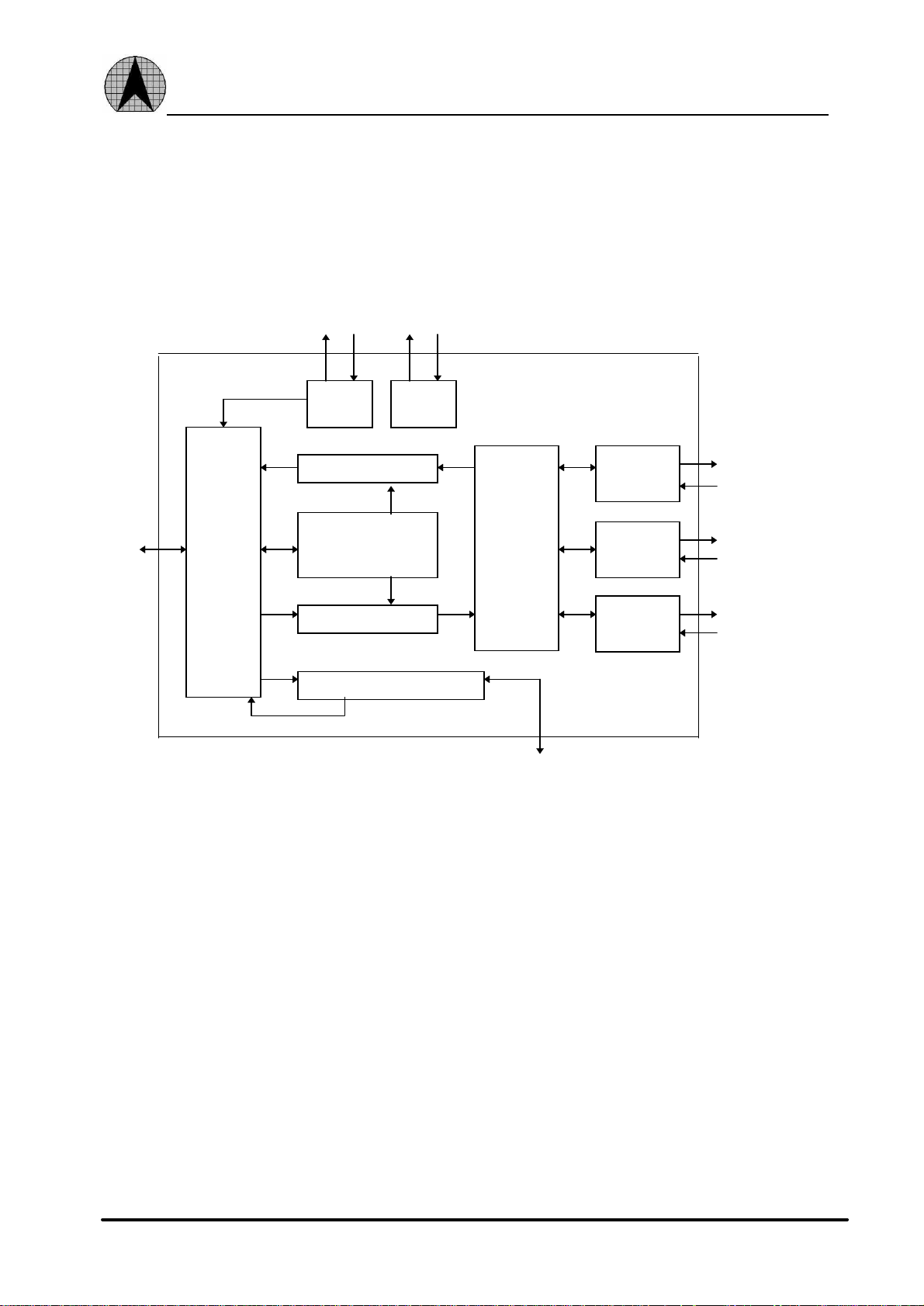
1.3 Block Diagram:
SERIAL BOOT ROM
ROOM Interface
Serial
ROM I/F
Receive FIFO
PCI SYM
BUS
PCI
BUS
Interface
Buffer
Management
DMA Engine
Transmit FIFO
General Purpose REG
BOOT
ROM I/F
Interface
MAC
Controller
General purpose I/O pins
Interface
Interface
MII
PCS
10 BT
MII
SRL
Fig - 1 AX88140A Block Diagram
8
ASIX ELECTRONICS CORPORATION

AX88140A PRELIMINARY
1.4 AX88140AQ Pin Connection Diagram for 160-pin
The AX88140A is housed in the 160-pin plastic quad flat pack. Fig - 2 shows the AX88140A
pin connection diagram.
nc
nc
nc
int#
rst#
vdd
vss
pci_clk
vdd
gnt#
req#
vss
ad<31>
ad<30>
vss
ad<29>
ad<28>
vss
ad<27>
ad<26>
vdd
ad<25>
ad<24>
c_be#<3>
idsel
vss
ad<23>
ad<22>
ad<21>
ad<20>
vdd
ad<19>
ad<18>
vdd
vss
vss
ad<17>
ad<16>
vss
nc
nc
10
11
12
13
14
15
16
17
18
19
20
21
22
23
24
25
26
27
28
29
30
31
32
33
34
35
36
37
38
39
40
nc
nc
160
159
158
1
2
3
4
5
6
7
8
9
nc
157
nc
156
nc
srl_txen
154
155
srl_tclk
srl_txd
152
153
srl_rclk
srl_rxen
150
151
srl_clsn
srl_rxd
148
149
mii/srl
147
mtxd<3>/symtxd<3>
mtxd<2>/symtxd<2>
145
144
vdd
143
mtxd<1>/symtxd<1>
vss
141
142
symtxd<4>
146
mtclk/symtclk
mtxd<0>/symtxd<0>
mtxen/symtxen
rcv_match
nc
vdd
vss
134
135
136
137
138
139
140
mrxd<2>/symrxd<2>
symrxd<4>
mrxd<3>/symrxd<3>
132
133
131
ASIX
88140AQ
43
45
44
41
42
50
49
48
47
46
55
54
53
52
51
60
59
58
57
56
65
64
63
62
61
70
69
68
67
66
mcol
mcrs
mrxdv
mrxerr
mrclk/symrclk
mrxd<1>/symrxd<1>
mrxd<0>/symrxd<0>
130
128
129
73
72
71
127
74
126
75
125
76
124
77
sd
123
nc
nc
121
122
120
119
118
117
116
115
114
113
112
111
110
109
108
107
106
105
104
103
102
101
100
78
79
80
99
98
97
96
95
94
93
92
91
90
89
88
87
86
85
84
83
82
81
nc
nc
vss
vdd
mdc
mdio
nc
br_a<1>
br_a<0>
brce#
br_ad<7>
br_ad<6>
vdd
vss
br_ad<5>
br_ad<4>
br_ad<3>
br_ad<2>
br_ad<1>
br_ad<0>
vss
genp<7>
genp<6>
genp<5>
genp<4>
vdd
vss
genp<3>
genp<2>
genp<1>
genp<0>
sr_cs
sr_ck
sr_di
sr_do
vdd
vss
vdd*
nc
nc
nc
nc
vss
irdy#
trdy#
frame#
devsel#
cbe#<2>
vdd
stop#
serr#
perr#
par
cbe#<1>
vss
ad<15>
ad<14>
vss
ad<13>
ad<12>
ad<11>
vdd
ad<10>
ad<09>
vss
ad<08>
ad<07>
ad<06>
cbe#<0>
vss
ad<05>
ad<04>
vdd
ad<03>
ad<02>
vss
Fig - 2 AX88140AQ Pin connection diagram for 160-pin
9
ASIX ELECTRONICS CORPORATION
ad<00>
ad<01>
nc
nc

AX88140A PRELIMINARY
1.5 AX88140AP Pin Connection Diagram for 144-pin
The AX88140A is housed in the 144-pin plastic quad flat pack. Fig - 3 shows the AX88140A
pin connection diagram.
mcol
mii_crs
mrxdv
mrxerr
mrclk/symrclk
110
111
112
113
114
sd
109
108
107
106
105
104
103
102
101
100
99
98
97
96
95
94
93
92
91
90
89
88
87
86
85
84
83
82
81
80
79
78
77
76
75
74
73
vss
vdd
mdc
mdio
nc
br_a<1>
br_a<0>
brce#
br_ad<7>
br_ad<6>
vdd
vss
br_ad<5>
br_ad<4>
br_ad<3>
br_ad<2>
br_ad<1>
br_ad<0>
vss
genp<7>
genp<6>
genp<5>
genp<5>
genp<4>
vdd
vss
genp<3>
genp<2>
genp<1>
genp<0>
sr_cs
sr_ck
sr_di
sr_do
vdd
vss
vdd*
int#
rst#
vdd
vss
pci_clk
vdd
gnt#
req#
vss
ad<31>
ad<30>
vss
ad<29>
ad<28>
vss
ad<27>
ad<26>
vdd
ad<25>
ad<24>
cbe#<3>
idsel
vss
ad<23>
ad<22>
ad<21>
ad<20>
vdd
ad<19>
ad<18>
vdd
vss
vss
ad<17>
ad<16>
vss
10
11
12
13
14
15
16
17
18
19
20
21
22
23
24
25
26
27
28
29
30
31
32
33
34
35
36
mii/srl
mtxd<3>/symtxd<3>
mtxd<2>/symtxd<2>
131
130
vdd
129
vss
128
mtxd<1>/symtxd<1>
nc
144
143
1
2
3
4
5
6
7
8
9
142
srl_txen
140
141
139
srl_txd
137
138
srl_tclk
nc
nc
nc
136
srl_rxd
134
135
symtxd<4>
132
133
srl_clsn
srl_rclk
srl_rxen
mtclk/symtclk
mtxd<0>/symtxd<0>
mtxen/symtxen
rcv_match
nc
122
123
124
125
126
127
mrxd<2>/symrxd<2>
symrxd<4>
vdd
vss
mrxd<3>/symrxd<3>
118
119
120
121
117
mrxd<1>/symrxd<1>
mrxd<0>/symrxd<0>
116
115
ASIX
88140AP
37
38
vss
cbe#<2>
40
39
irdy#
frame#
41
trdy#
devsel#
42
44
43
vdd
stop#
45
perr#
46
serr#
48
47
par
cbe#<1>
49
vss
51
50
ad<15>
ad<14>
ad<13>
52
53
vss
ad<12>
54
ad<11>
55
56
vdd
ad<10>
58
57
ad<09>
60
59
vss
ad<08>
63
62
61
ad<07>
ad<06>
cbe#<0>
64
vss
66
65
ad<05>
ad<04>
67
vdd
ad<03>
69
68
ad<02>
70
vss
ad<01>
71
Fig - 3 AX88140AP Pin connection diagram for 144-pin
10
ASIX ELECTRONICS CORPORATION
72
ad<00>

AX88140A PRELIMINARY
2.0 Signal Description
2.1 Signal Descriptions for 160-pin and 144-pin
The following terms describe the AX88140A pin-out:
l Address phase
Address and appropriate bus commands are driven during this cycle.
l Data phase
Data and the appropriate byte enable codes are driven during this cycle.
l #
All pin names with the # suffix are asserted low.
The following abbreviations are used in Tab - 1 PCI interface group Tab - 2 Boot ROM , Serial ROM , General-
purpose signals group ,Tab - 3 MII/SYM/SRL interface signals group ,Tab - 4 Extended , NC, Power pins group..
I Input
O Output
I/O Input /Output
O/D Open Drain
11
ASIX ELECTRONICS CORPORATION

AX88140A PRELIMINARY
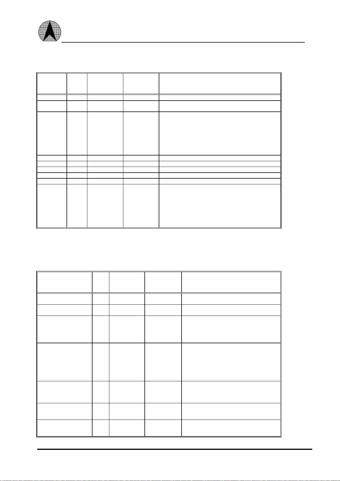
2.2 PCI interface group
SIGNAL TYPE PIN
NUMBER
FOR 160 PIN
AD<31>
AD<30>
AD<29>
AD<28>
AD<27>
AD<26>
AD<25>
AD<24>
AD<23>
AD<22>
AD<21>
AD<20>
AD<19>
AD<18>
AD<17>
AD<16>
AD<15>
AD<14>
AD<13>
AD<12>
AD<11>
AD<10>
AD<9>
AD<8>
AD<7>
AD<6>
AD<5>
AD<4>
AD<3>
AD<2>
AD<1>
AD<0>
CBE#<3>
CBE#<2>
CBE#<1>
CBE#<0>
DEVSEL# I/O 48 42 Device select Is asserted by the target of the current bus access.
FRAME# I/O 45 39 The FRAME# Signal is driven by the AX88140A To indicate the
GNT# I 9 7 BUS GRANT Indicates to the AX88140A That access to the bus is
IDSEL I 24 22 Initialization devise select asserts To indicate that the host is
INT# O/D 3 1 Interrupt request asserts When one of the appropriate bits of reg5
IRDY# I/O 46 40
I/O 12,
13,
15,
16,
18,
19,
21,
22,
26,
27,
28,
29,
31,
32,
36,
37,
56,
57,
58,
60,
61,
63,
64,
66,
68,
69,
71,
72,
74,
75,
77,
78
I/O 23,
44,
54,
67
PIN
NUMBER
FOR 144 PIN
10,
11,
13,
14,
16,
17,
19,
20,
24,
25,
26,
27,
29,
30,
34,
35,
50,
51,
52,
54,
55,
57,
58,
60,
62,
63,
65,
66,
68,
69,
71,
72
21,
38,
48,
61
DESCRIPTION
Address and data bits are multiplexed on the samepins. During the
address phase, the AD<31:0> contain a physical address (32 bits).
During, data phases, AD<31:0> contain 32 bits of data.
The AX88140A supports both read and write bursts (in master
operation only). Little and big endian byte ordering can be used.
BUS COMMAND and BYTE ENABLE Are multiplexed on the
same PCI pins. During the address phase of the transaction,
CBE#<3:0> Provide the BUSCOMMAND.During the data phase,
CBE#<3:0> Provide the BYTE ENABLE. The BYTE ENABLE
determines which byte lines carry valid data., CBE#<0> Applies to
byte 0, and CBE#<3> Applies to byte 3.
When the AX88140A is the master of the current bus access, the
target assert DEVSEL# confirming the access. It is driven by
AX88140A When AX88140A is selected as a slave.
beginning and duration of an access. FRAME# Asserts to indicate
the beginning of a bus transaction. While FRAME# is asserted,
data transfers continue. When FRAME# deasserts the next data
phase is the final data phase transaction.
granted.
issuing a configuration cycle to the AX88140A.
sets and causes an interrupt, provided that the corresponding mask
bit in reg7 is not asserted. interruptrequest deasserts by writing a 1
into the appropriate crs5 bit.
This pin must be pulled up by an external resistor.
Initiator ready Indicates the bus master ability to complete the
current data phase of the transaction.
A data phase is completed on any rising edge of the clock When
both IRDY# and target ready TRDY# are asserted. Waitcycles are
inserted until both IRDY# and TRDY# are asserted together.
When the AX88140A is the bus master, IRDY# is asserted during
write operations to indicate that valid data is present on the
AD<31:0>. During read operations, the AX88140A asserts
12
ASIX ELECTRONICS CORPORATION

AX88140A PRELIMINARY
IRDY# to indicate that it is ready to accept data.
PAR I/O 53 47 Parity is an even parity bit for the AD<31:0> AD and CBE#<3:0>.
PCI_CLK I 7 5 The clock provides the timing for the AX88140A related PCI bus
PERR# I/O 51 45 Parity error asserts when a data parity error is detected. When the
REQ# O 10 8 Bus request is asserted by the AX88140A to indicate to the bus
RST# I 4 2 Resets the AX88140A to its initial state. This signal must be
SERR# I/O 52 46 System Error is used by AX88140A to report address parity Error.
STOP# I/O 49 43 Stop indicator indicates that the current target is requesting the bus
TRDY# I/O 47 41 Target ready indicates thetargetability tocompletethe current data
During address and data phases, parity is calculated on all the
AD<31:0> AND CBE#<3:0>lines whether or not any of these
lines carry meaningful information.
transactions. All the bus signals are sampled on the rising edge of
PCI_CLK. The clock frequency range is between 21MHZ and
33MHZ.
AX88140A is the bus master it monitor PERR# to see if the target
report a data parity error., when the AX88140A is the bus target
and a parity error is detected, the AX88140A asserts PERR#. This
pin must be pulled up by an external resistor.
arbiter that it wants to use the bus.
asserted for at least 10 active PCI clock cycles. When is the reset
state, all PCI output pins are put into tri-state and all PCI o/d
signals are floated.
This pin must be pulled up by an external resistor.
master to stop the current transaction. The AX88140A responds to
the assertion of STOP# when it is the bus master, and stop the
current transaction.
phase of the transaction.
A data phase is completed on any clock when both TRDY# and
IRDY# are asserted. Wait cycles are inserted until both IRDY#
and TRDY# are asserted together. When the AX88140A is the bus
master, target ready is asserted by the bus slave on the read
operation, indicating that valid data is present on the ad lines.
During a write cycle, it indicates that the target is prepared to
accept data.
Tab - 1 PCI interface group
13
ASIX ELECTRONICS CORPORATION
AX88140A PRELIMINARY
2.3 Boot ROM , Serial ROM , General-purpose signals group
SIGNAL TYPE PIN
NUMBER
FOR 160 PIN
BR_A<0> 0 112 102 Boot ROM address line bit 0.
BR_A<1> 0 113 103 Boot ROM address line bit 1. This pin also latches the boot ROM
BR_AD<7>
BR_AD<6>
BR_AD<5>
BR_AD<4>
BR_AD<3>
BR_AD<2>
BR_AD<1>
BR_AD<0>
BR_CE# O 111 101 Boot ROM chip enable.
SR_CK O 88 78 Serial ROM clock signal.
SR_CS O 89 79 Serial ROM chip-select signal.
SR_DI O 87 77 Serial ROM data-in signal.
SR_DO I 86 76 Serial ROM data-out signal.
GENP<7>
GENP<6>
GENP<5>
GENP<4>
GENP<3>
GENP<2>
GENP<1>
GENP<0>
I/O 110,
109,
106,
105,
104,
103,
102,
101
I/O 99,
98,
97,
96,
93,
92,
91,
90
PIN
NUMBER
FOR 144 PIN
100,
99,
96,
95,
94,
93,
92,
91
89,
88,
87,
86,
83,
82,
81,
80
DESCRIPTION
address and control lines by the two external latches.
Boot ROM address and data multiplexed lines bits 7 through 0. In
the first of two consecutive address cycles, these lines contain the
boot ROM address bits 9 through 2; followed by boot ROM
address bits 17 through 10 in the second cycle. During the data
cycle, bits 7 through 0 contain data.
General-purpose pins can be used by software as either status pins
or control pins. These pins can be configured by software to
perform either input or output functions.
Tab - 2 Boot ROM , Serial ROM , General-purpose signals group
2.4 MII/SYM/SRL interface signals group
SIGNAL TYPE PIN
NUMBER
FOR 160 PIN
MCOL I 126 112 Collision detected is asserted when detected by an
MCRS I 127 113 Carrier sense is asserted by the PHY when the media
MRXDV I 125 111 Data valid is asserted by an external PHY when
MRXERR I 124 110 Receive error asserts when a data decoding error is
MDC O 116 106 MII management data clock is sourced by the
MDIO I/O 115 105 MII management data input/output transfers control
MII/SRL O 147 133 Indicates the selected port: SRL or MII/SYM. When
PIN
NUMBER
FOR 144 PIN
DESCRIPTION
external physical layer protocol(PHY) device.
is active.
receive data is present on the MRXD/SYRXD lines
and is deasserted at the end of the packet. This signal
should be synchronized with the
MRCLK/SYMRCLK signal.
detected by an external PHY device. This signal is
synchronized to MRCLK/SYMRCLK and can be
asserted for a minimum of one receive clock. When
asserted during a packet reception, it sets the cyclic
redundancy check(CRC) error bit in the receive
descriptor (RDESO).
AX88140A to the PHY devices as a timing reference
for the transfer of information on the MII_MDIO
signal.
information and status between the PHY and the
AX88140A.
asserted, the MII/SYM port is active. When
deasserted, the SRL port is active.
14
ASIX ELECTRONICS CORPORATION
 Loading...