

Page 1

Asis ATCA
Shelf Manager Board
User Manual
May 2014 Revision 1.2
Page 2

Table of Contents
ATCA Shelf Manager Board ii Revision 1.2
Asis, the ATCA experts
Table of Contents
TABLE OF CONTENTS ................................................................................. II
TABLE OF FIGURES ................................................................................... III
LEGAL NOTICE AND WARRAENTY .............................................................. IV
CONTACT INFORMATION ............................................................................ V
SAFETY INSTRUCTIONS ............................................................................. VI
REVISION HISTORY ................................................................................. VII
ABOUT THIS DOCUMENT ......................................................................... VIII
1 INTRODUCTION .............................................................................. 10
1.1 SHELF MANAGER BOARD ........................................................................... 10
1.1.1 Features ...................................................................................... 12
1.1.2 Front Panel ................................................................................... 13
2 UNDERSTANDING THE BOARD COMPONENTS ................................. 14
2.1 VISUAL INDICATORS ................................................................................ 14
2.2 EXTERNAL CONNECTIONS .......................................................................... 16
2.2.1 Telco Alarm Connector ................................................................... 16
2.2.2 Serial RS232 (Console) Connector ................................................... 17
2.2.3 Ethernet Connector ....................................................................... 17
2.3 JUMPERS ............................................................................................. 18
3 REPLACING THE CARD AND COMPONENTS ..................................... 19
3.1 INSERTING THE SHELF MANAGER CARD ......................................................... 19
3.2 SHELF MANAGER BOARD BATTERY REPLACEMENT .............................................. 19
4 SOFTWARE COMMANDS .................................................................. 21
4.1 GENERAL ............................................................................................. 21
4.2 CONSOLE CONNECTION ............................................................................ 21
4.3 MANAGEMENT COMMANDS ......................................................................... 23
5 ASIS ATCA SHELF ACRONYMS ......................................................... 25
Page 3

Table of Figures
ATCA Shelf Manager Board iii Revision 1.2
Asis, the ATCA experts
Table of Figures
FIGURE 1 - BLOCK DIAGRAM OF SHELF MANAGER BOARD .................................................... 11
FIGURE 2 – BOARD LAYOUT ....................................................................................... 12
FIGURE 3 – FRONT PANEL ......................................................................................... 13
FIGURE 4 – LED'S ON THE SHELF MANAGER BOARD FRONT PANEL .......................................... 14
FIGURE 5 – SHELF INTERCONNECT ............................................................................... 18
FIGURE 6 – SHELF MANAGER BOARD INSERTION ............................................................... 19
FIGURE 7 - THE HYPERTERMINAL SCREEN ....................................................................... 22
FIGURE 8 - SERIAL PORT CONFIGURATION SCREEN ............................................................ 22
Page 4

Legal Notice and Warraenty
ATCA Shelf Manager Board iv Revision 1.2
Asis, the ATCA experts
Legal Notice and Warraenty
Information in this document is provided in connection with Asis products. no license,
express or implied, by estoppel or otherwise, to any intellectual property rights is granted
by this document. except as provided in Asis terms and conditions of sale for such
products, Asis assumes no liability whatsoever, and Asis disclaims any expressed or
implied warranty, relating to sale and/or use of asis products including liability or
warranties relating to fitness for a particular purpose, merchant ability, or infringement of
any patent, copyright or other intellectual property right.
Asis warranty will be for the quality of the Asis ATCA Shelf Manager Board for a period of
one year after the shipment of the product.
Asis may make changes to specifications and product descriptions at any time, without
notice.
ASIS © Ltd. 2007
Page 5

Contact Information
ATCA Shelf Manager Board v Revision 1.2
Asis, the ATCA experts
Contact Information
In order to retrieve further information about any of Asis products either described in this
document and/or related systems and/or components, please contact an ASIS
representative at:
Israel Headquarters
27 Shaked St.
Industrial Park - Hevel Modi’in,
6085102 Israel
Telephone: +972-73-233-6600
See the ASIS web site at http://www.asis-pro.com
Page 6
Safety Instructions
ATCA Shelf Manager Board vi Revision 1.2
Asis, the ATCA experts
Safety Instructions
This symbol indicates potential safety hazards regarding product operation or
maintenance to operator or service personnel.
General Safety Practices
Before handling the board, read the instructions and safety guidelines on the following
pages to prevent damage to the product and to ensure your own personal safety.
Always use caution when handling/operating the board. Only qualified,
experienced, authorized electronics service personnel should access the
interior of the equipment.
Always follow the procedural instructions for component removal and
replacement in sequence.
Working with Lithium Batteries
Your Shelf manager board may have a non-rechargeable lithium battery.
Do not short circuit
Do not heat or incinerate
Do not charge
Do not deform or disassemble
Do not apply solder directly
Do not mix different types or partially-used batteries together
Always observe proper polarities.
Page 7
Revision History
ATCA Shelf Manager Board vii Revision 1.2
Asis, the ATCA experts
Revision History
Number
Date
Comments
Author
1.0.1
Sep 2007
Initial release
Yossi Kuzi
1.0.2
Dec 2008
Addition of the battery isolation film removal
Ilan Bar
1.2
May 2014
Front panel LEDs and push-buttons
Boaz Bar-Ilan
Page 8
About this Document
ATCA Shelf Manager Board viii Revision 1.2
Asis, the ATCA experts
About this Document
This document provides technical information for the Asis Perform 14 slots Shelf
Manager board.
It is intended for technical staff tasked with installing, setting up and configuring the
system, and providing troubleshooting assistance and servicing.
Related Documents
Instructions relating to software installation and documentation for application software
development for this platform are available in the Shelf Manager External Interface Reference
Manual provided by peigon point to Asis.
Instructions relating to software installation and documentation for application software
development for this platform are available in the Shelf Manager External Interface
Reference Manual.
For Asis product information and additional resources, please visit the Asis website at
www.asis-pro.com.
Downloads (manuals, release notes, software, etc.) are available via the Technical
Support Library product links at www.asis-pro.com (for registered customers).
Information about PICMG (PCI Industrial Computer Manufacturers Group) and the ATCA
standard may be accessed on the PICMG Web site at www.picmg.com.
Chapters and Their Contents
1
Introduction
General overview of the product family and the board.
Pg. 10
2
Understanding the Board
Components
the functional features and components of the board
Pg. 14
3
Software Commands
this chapter contains the software commands needed
to manage the shelf
Pg. 21
Page 9
About this Document
ATCA Shelf Manager Board ix Revision 1.2
Asis, the ATCA experts
Style Conventions
Verdana
Regular text.
Arial Bold
Commands, keys and other parts of the user interface.
Arial Italics
Names of classes, methods, arguments, exceptions, properties, etc.
Also used for special terms, the first time they appear.
Monospace
Text displayed on the LCD or on a computer attached to the product.
Notes, which offer an additional explanation or a hint on how to
overcome a common problem.
Warnings, which indicate potential safety hazards regarding product
operation or maintenance to operator or service personnel.
Page 10

Introduction
Shelf manager Board
ATCA Shelf Manager Board 10 Revision 1.2
Asis, the ATCA experts
1 Introduction
1.1 Shelf manager Board
The ASIS ATCA shelf is designed to comply with all relevant ATCA specifications, including
the IPMI 1.5 (Intelligent Platform Management Interface) specifications.
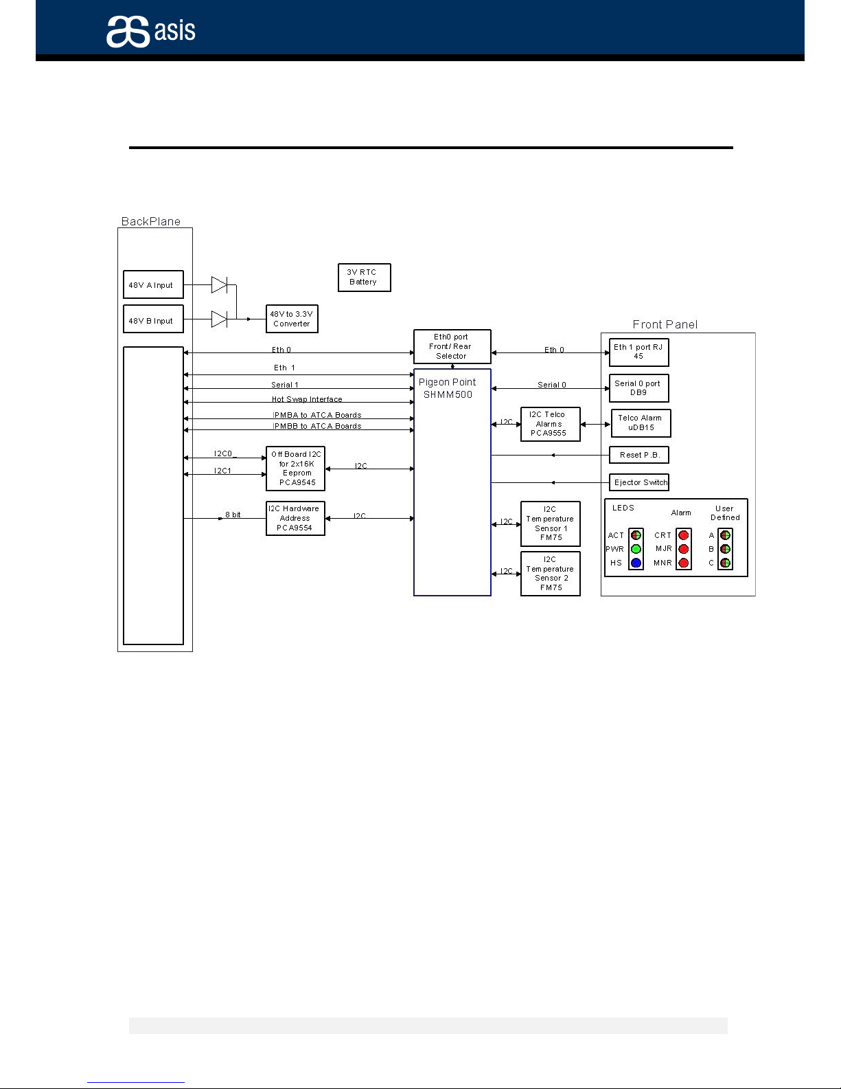
The Shelf Manager monitors the shelf temperature sensors, collecting status information,
generate alarms, control the indication displays and the fan trays.
It's of remote control capable. It supports multiple management interfaces, including:
RMCP, RPC, SNMP, CLI and Web Interface.
Page 11
Introduction
Shelf manager Board
ATCA Shelf Manager Board 11 Revision 1.2
Asis, the ATCA experts
Figure 1 - Block Diagram of Shelf Manager Board
Shelf Manager Board
Page 12
Introduction
Shelf manager Board
ATCA Shelf Manager Board 12 Revision 1.2
Asis, the ATCA experts
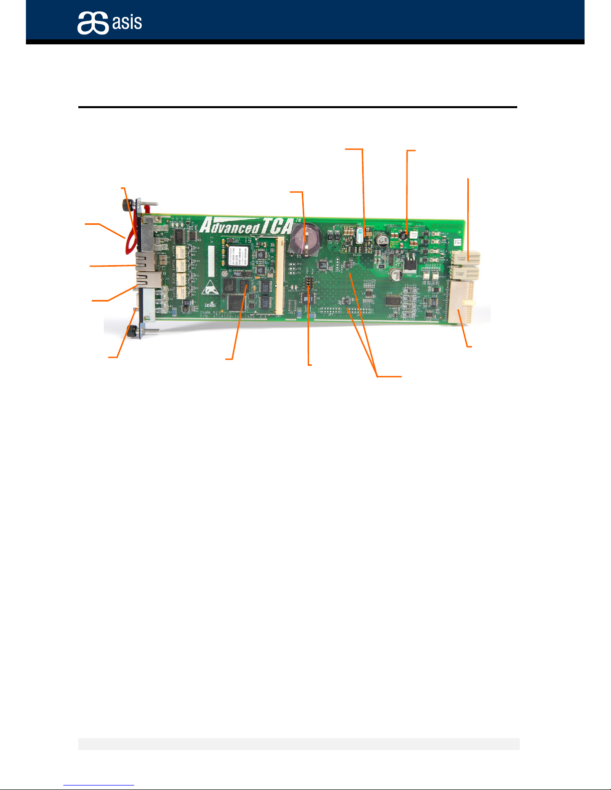
Figure 2 – Board Layout
1.1.1 Features
The Shelf Manager Board is an FRU with the following features and functionality:
Fan tray control – controlling the fan trays thru the IPMB
Providing 3.3V to other parts of the board
Intake air temperature monitoring
LED Alarms display
Telco Alarms control and display
Hosting of the Pigeon point ShMM500 management module
Front Ethernet connection.
Rear Ethernet connection.
RJ11 serial port.
Reset button.
Hot wasp capability with hot wasp handle.
Front Panel’s
LED group
TMP sensors
Eth port
Serial
(RS232)
Telco Alarm
Pigeon Point
SHMM module
JP 1
BP Data
Connector
48V PWR filter
PWR connector:
48VDc from
Pem
RTC 3V Battery
48V to 3.3V
CONVERTER
Hot
Swap
Handle
Page 13
Introduction
Shelf manager Board
ATCA Shelf Manager Board 13 Revision 1.2
Asis, the ATCA experts
1.1.2 Front Panel
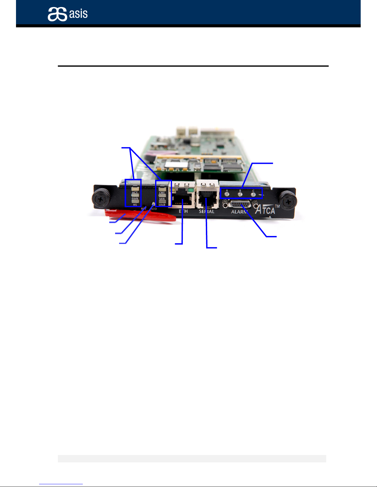
The Shelf Manager board’s front panel contains the display as shown in figure 3:
Figure 3 – Front Panel
COM (RS232)
port
Telco alarm port
ATCA LEDs
Applicationdefined LEDs
ETH port
Alarm Cutoff PB
Reset PB
Hot Swap handle
Page 14
Understanding the Board Components
Visual Indicators
ATCA Shelf Manager Board 14 Revision 1.2
Asis, the ATCA experts
2 Understanding the Board Components
This chapter summarizes the functional features and components of the board.
The board was designed to withstand extreme conditions (to meet rigid Telco
requirements). It is a Field-Replaceable Unit (FRU), and is fully field-serviceable.
2.1 Visual Indicators
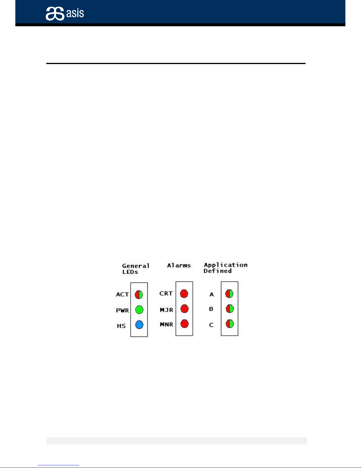
The front panel of the shelf manager board features nine LEDs arranged in three groups:
General LEDs
Alarm LEDs
Application-defined LEDs
The front panel includes 2 push-buttons: RST for booting the board (HW reset) and ACO
to reset the Telco Alarm lines.
Boot-up LED Status
At Power up all LED's light up for about 40 seconds during shelf manager board boot-up.
Figure 4 – LED's on the shelf manager Board Front Panel
Page 15
Understanding the Board Components
Visual Indicators
ATCA Shelf Manager Board 15 Revision 1.2
Asis, the ATCA experts
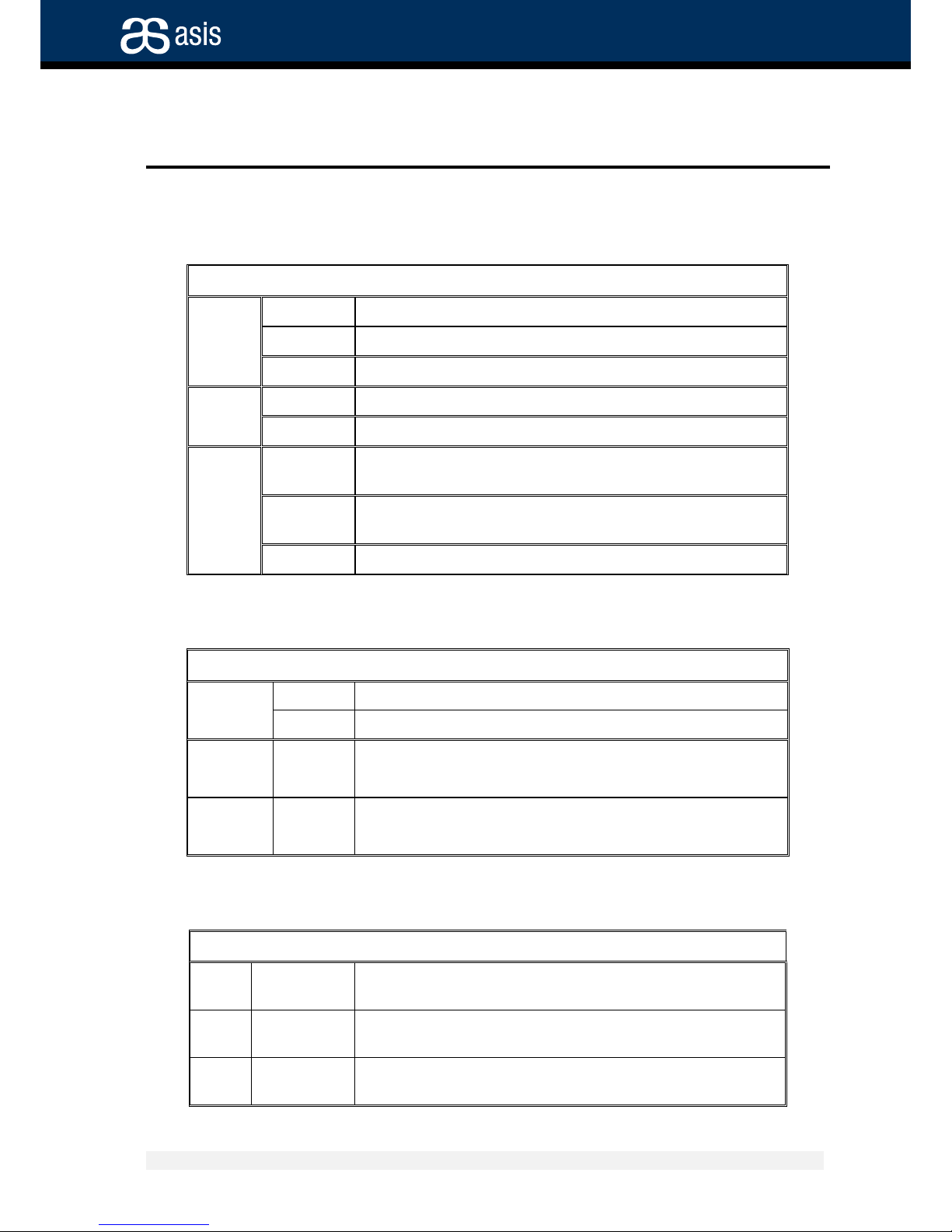
LED Functions: General LEDs
LED Status Meaning
ACT
Green
Shelf manager board active
Red
Shelf manager board failure
Blink
Shelf manager board inactive
PWR
Green
Local voltage supply on Shelf manager board
Off
Local voltage failure
HS
(hot
swap)
Steady
Blue
Shelf manager board powering up or ready for
extraction
Blinking
blue
Shelf manager board hot swap process
Off
Shelf manager board operating
LED Functions: Telco Alarm LEDs
LED Status Meaning
CRT
(Critical)
Off
Normal operation
Red
System alarm event
MJR
(Major)
Off
Normal operation
Red
System alarm event
MNR
(Minor)
Off
Normal operation
Red
System alarm event
LED Functions: Application-Defined LEDs
LED Status Meaning
A
Green/red/
bi-color
As defined by application (listed as LED 1 by software)
B
Green/red/
bi-color
As defined by application (listed as LED 2 by software)
C
Green/red/
bi-color
As defined by application (listed as LED 3 by software)
Page 16
Understanding the Board Components
External Connections
ATCA Shelf Manager Board 16 Revision 1.2
Asis, the ATCA experts
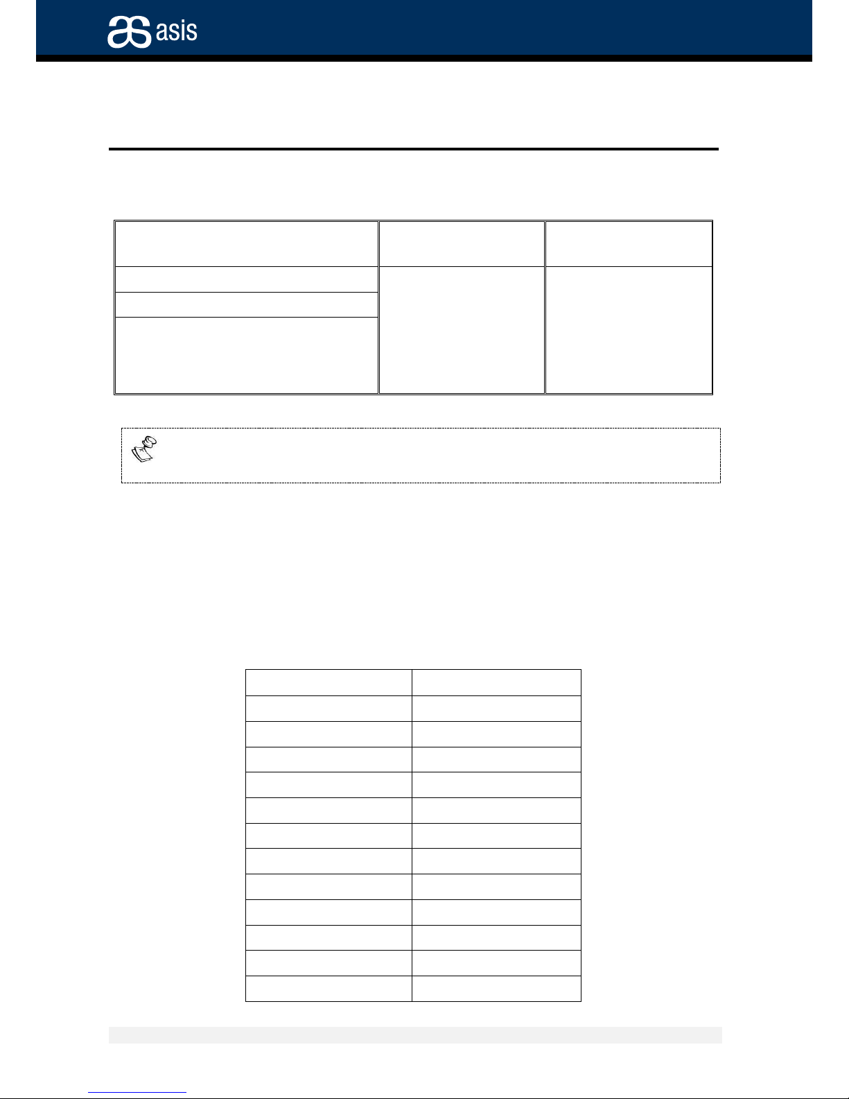
Upon completion of boot-up, LEDs will display as follows:
General LEDs
Telco Alarm LEDs
Application
Defined LEDs
ACT
back to normal state
OFF
OFF
PWR
Remains ON
HS
Lights steady blue for a
few seconds, then begins
blinking, then goes off
after a few blinks
When a user-defined dual color LED is on and colored green and red (as during
boot-up), the visible color is orange.
2.2 External Connections
The shelf manager Board features three connectors on its front panel. Pin-out description
of each connector is provided in this section.
2.2.1 Telco Alarm Connector
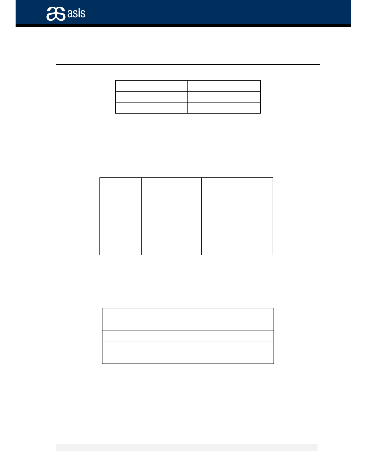
The Telco Alarm mini D-type 15 pin connector has the following pin definition:
Pin
Signal Name
1
Minor Reset Plus
2
Minor Reset Minus
3
Major Reset Plus
4
Major Reset Minus
5
Critical Alarm -NO
6
Critical Alarm -NC
7
Critical Alarm -COM
8
Minor Alarm – NO
9
Minor Alarm – NC
10
Minor Alarm – COM
11
Major Alarm – NO
12
Major Alarm – NC
Page 17
Understanding the Board Components
External Connections
ATCA Shelf Manager Board 17 Revision 1.2
Asis, the ATCA experts
13
Major Alarm – COM
14
Power Alarm – NO
15
Power Alarm -COM
The Alarm Cutoff (ACO) push button resets the Telco Alarm output lines to their normal
state.
2.2.2 Serial RS232 (Console) Connector
The Serial RS232 (Console) connector is a RG 11, DTE serial port with the following
pin-out definition (looking from the front the first pin is on the left):
Pin
Signal name
Description
1
not connected
2
RxD
In Receive Data
3
TxD
Out Transmit Data
4
not connected
5
SGND
Signal Ground
6
not connected
2.2.3 Ethernet Connector
The Ethernet connector is a standard RJ45-8 jack with the following pin-out definition,
looking form the front the first pin is on the left:
Pin
Signal name
Description
1
TxD+
Out Transmit Data Plus
2
TxD-
Out Transmit Data Minus
3
RxD+
In Receive Data Plus
6
RxD-
In Receive Data Minus
The following is indicated by the Ethernet connector LED's:
Green – Line activity;
Yellow - If lit, connection speed is 100 Mbit/s; otherwise speed is 10
Mbit/s
Note: the board front panel LEDs are lit even in case eth0 is routed to the backplane
Page 18
Understanding the Board Components
Jumpers
ATCA Shelf Manager Board 18 Revision 1.2
Asis, the ATCA experts
Eth0 port
Connect
Between
two ShMC’s
A B C D
E F G H
ShMC Cross
Connect
1
ShMC Cross
Connect
2
Hub
1
A B C D
E F G H
ShMC Cross
Connect
1
ShMC Cross
Connect
2
Hub
2
ShMC
1
Eth 0 ShMC
2
Eth 0 ShMC
2
Eth
1
Rear Access
2
ShMC
1
Eth 0 ShMC
2
Eth
0
SHMM
300 / 500
Eth
0
-
Carrier
Front Panel
Eth
0
Eth 1 Jumpers
Jumpers
Jumpers
ShMC
1
1 2 3
USB
To / From
ShMC port
1
To / From
second SHMM
To / From
Rear card
To / From
ShMC port
2
SHMM
300 / 500
Eth
0 - Carrier
Front Panel
Eth 0 Eth 1 Jumpers
Jumpers
Jumpers
ShMC
2
1 2 3
USB
To / From
ShMC port
1
To / From
second SHMM
To / From
Rear Card
To / From
ShMC port
2 [ Eth
0
Rear 1 ] [ Eth
0
Rear 2 ]
Rear Access
1
ShMC
1
Eth
1
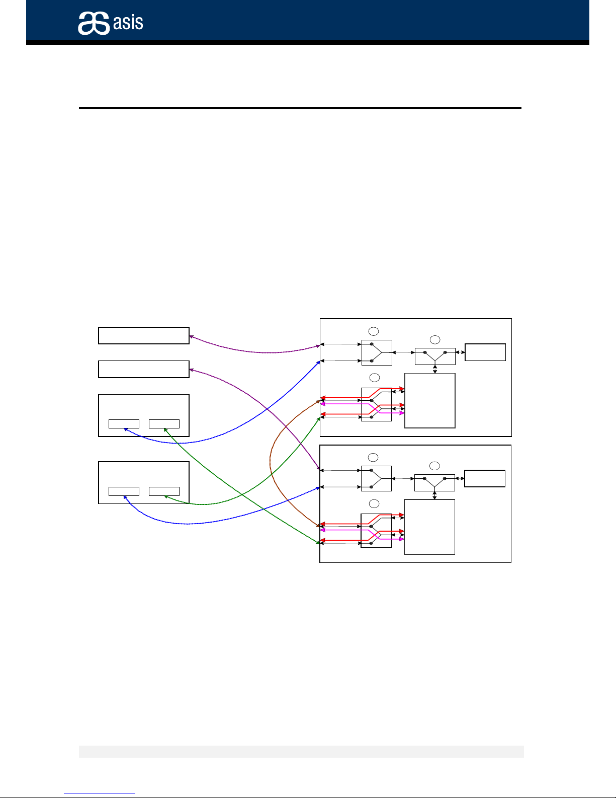
2.3 Jumpers
One jumper is used to select the connection of the Ethernet and Console ports either to
the Shelf manager board's front panel, or to the rear connector board's panel.
The jumper, located on the Shelf Manager card, is marked: JP1.
JP1 selects the connectivity between the Front panel and backplane access.
All four connectors must be connected to the same position (pins 1-2 or 2-3) and they
function as follows:
Jumpers connected between pins 1-2: the front connection is active
Jumpers connected between pins 2-3: the rear connection is active.
Figure 5 – Shelf interconnect
Page 19
Replacing the Card and Components
Inserting the Shelf Manager Card
ATCA Shelf Manager Board 19 Revision 1.2
Asis, the ATCA experts
3 Replacing the Card and Components
3.1 Inserting the Shelf Manager Card
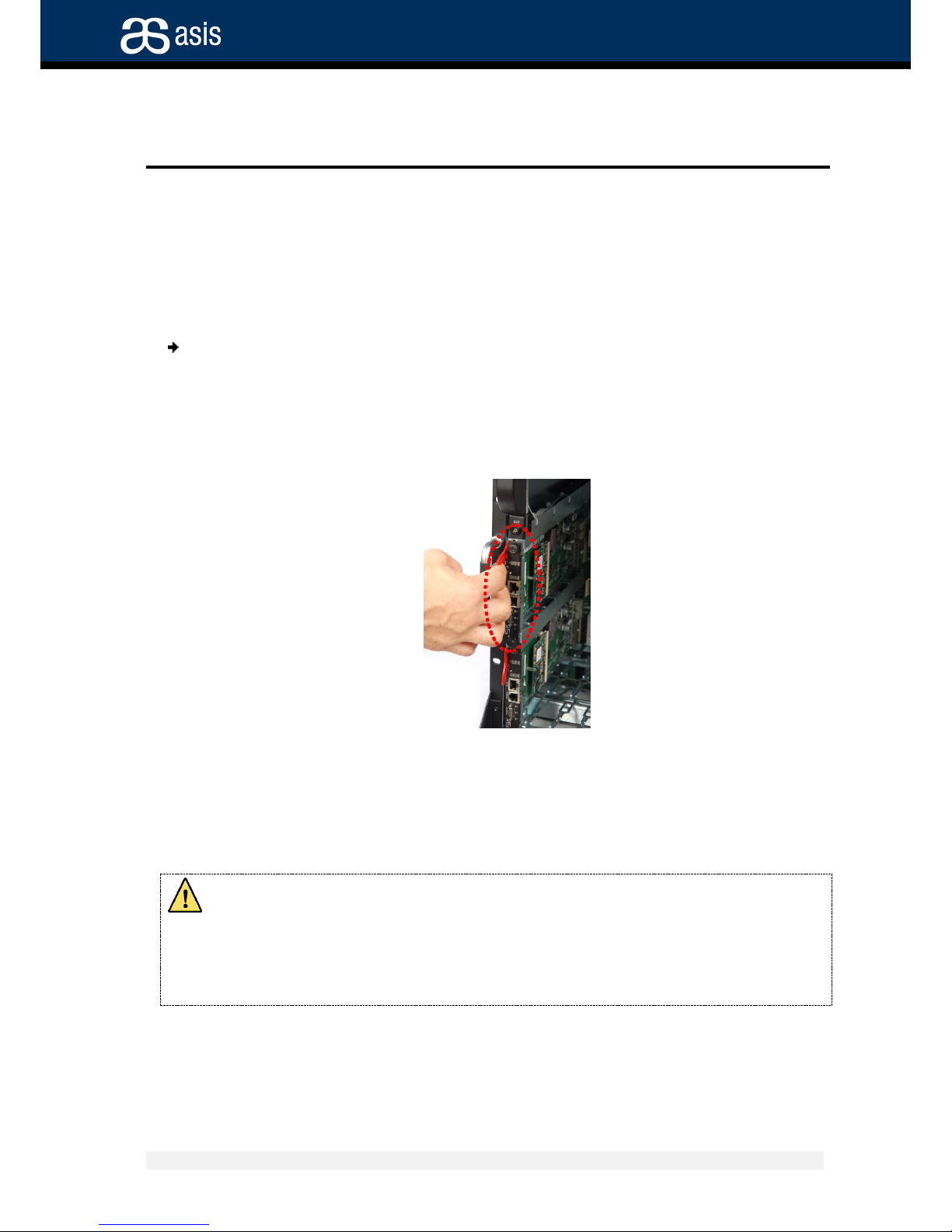
To insert the carrier board:
1. Carefully Insert the Shelf Manager card on the slot, making sure Inserting the
insertion lever into the right position and that it plugs firmly into it's place.
2. Fasten the locking screws on both top & bottom of the board's front panel.
3. Make sure that after about 40 seconds the blue led (hot swap) is off.
Figure 6 – shelf manager Board Insertion
3.2 Shelf manager Board Battery Replacement
The Shelf Manager board contains a lithium battery. There is a danger of explosion if the
battery is incorrectly replaced or handled.
Do not disassemble or recharge the battery. Do not dispose of the battery in fire.
When the battery is replaced, the same type or an equivalent type recommended
by the manufacturer must be used.
Used batteries must be disposed of according to the manufacturer's instructions.
Page 20
Replacing the Card and Components
Shelf manager Board Battery Replacement
ATCA Shelf Manager Board 20 Revision 1.2
Asis, the ATCA experts
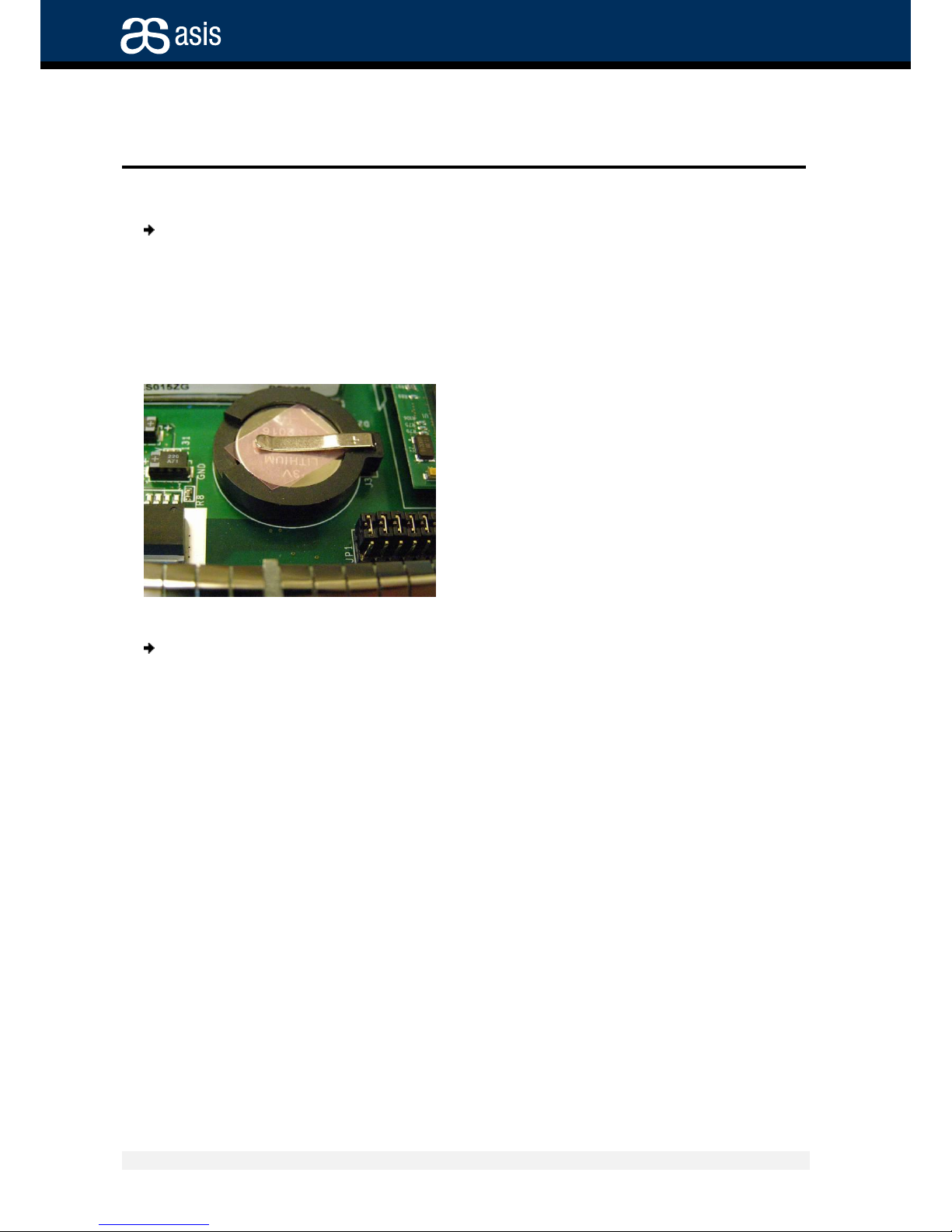
Removal of the battery isolation film:
The isolation film protects the battery and saves it's energy prior to using it. Before
using a brand new shelf manager, remove the isolation film. See the below picture.
1. Lift the battery clamp and remove the isolator.
2. Release the clamp.
To replace the battery:
1. Lift the battery clamp and remove the old battery.
2. Insert a new CR2016 lithium battery or equal.
3. Release the clamp.
The battery exchange must be completed within less than one minute.
Battery Backup Characteristics
Battery Voltage: 3V
Battery Capacity: 48mAh
Power applied for 24 hours per day
Electrochemical Construction:
Long-life lithium with solid-state cathode.
Page 21

Software Commands
General
ATCA Shelf Manager Board 21 Revision 1.2
Asis, the ATCA experts
4 Software Commands
4.1 General
The ASIS shelf manager Board contains software necessary to manage the shelf and
communicate with the intelligent management control software from an external console.
The external interfaces supported include:
a command-line interface (CLI).
a WEB interface.
a Simple Network Management Protocol (SNMP) interface.
a Remote Management Control Protocol (RMCP) interface.
Administrators can access the shelf to retrieve information on the current status of the
shelf, including:
current FRU population.
current sensor values.
threshold settings.
recent events.
overall shelf health.
Please refer to the Shelf Management External Interface Reference Manual provided by Pigeon
Point to Asis for further details on programmatic interface with the shelf.
4.2 Console Connection
A dumb terminal or a PC with terminal-emulation software should be connected to the
RS232 Console port on the active Shelf Manager board.
Serial D type 9 pin female to rj11 converter with RJ11 communications cable is required.
When a PC terminal emulator is used, the communication cable should be
connected to a free communications port (COM1 or COM2), and the connection
should be defined in the HyperTerminal program (see Figure 6).
Page 22
Software Commands
Console Connection
ATCA Shelf Manager Board 22 Revision 1.2
Asis, the ATCA experts
Figure 7 - The HyperTerminal screen
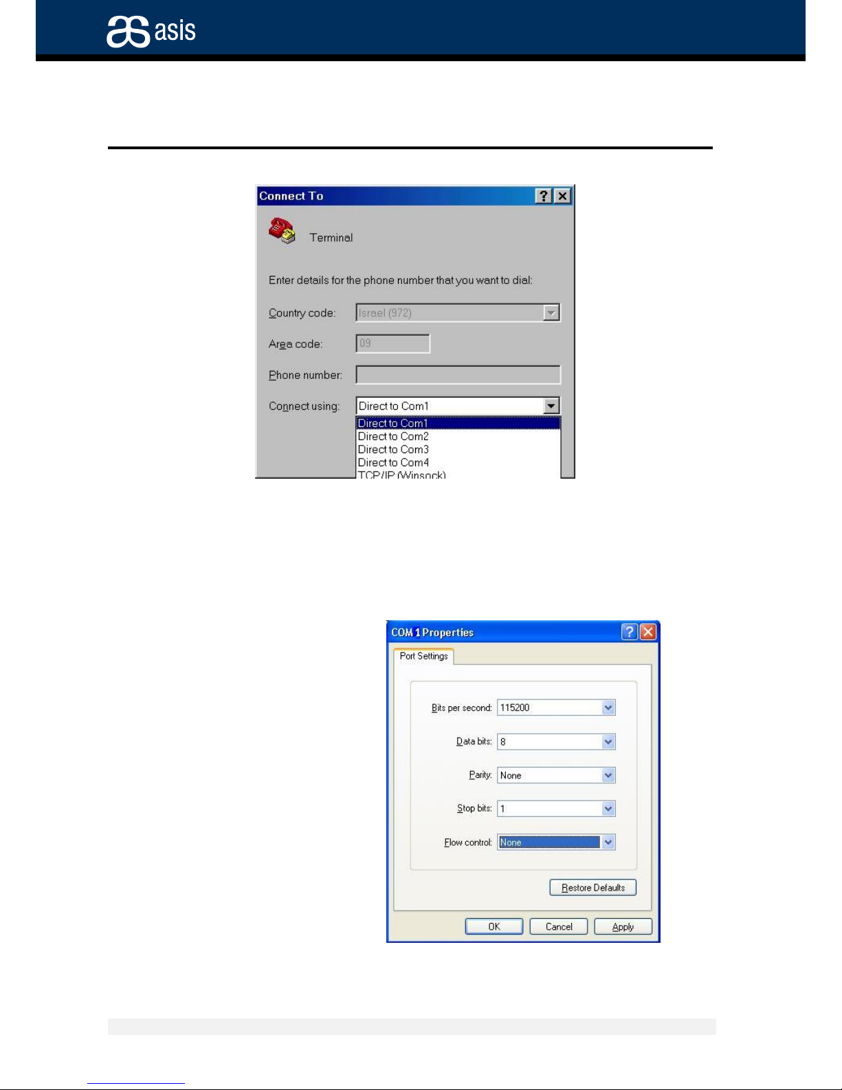
The following parameters should be defined in the Port Settings tab of the COM Properties
dialog, see Figure 7:
Bits per second
Parity
Stop bits
Flow control.
Figure 8 - Serial Port Configuration Screen
Page 23
Software Commands
Management Commands
ATCA Shelf Manager Board 23 Revision 1.2
Asis, the ATCA experts
4.3 Management Commands
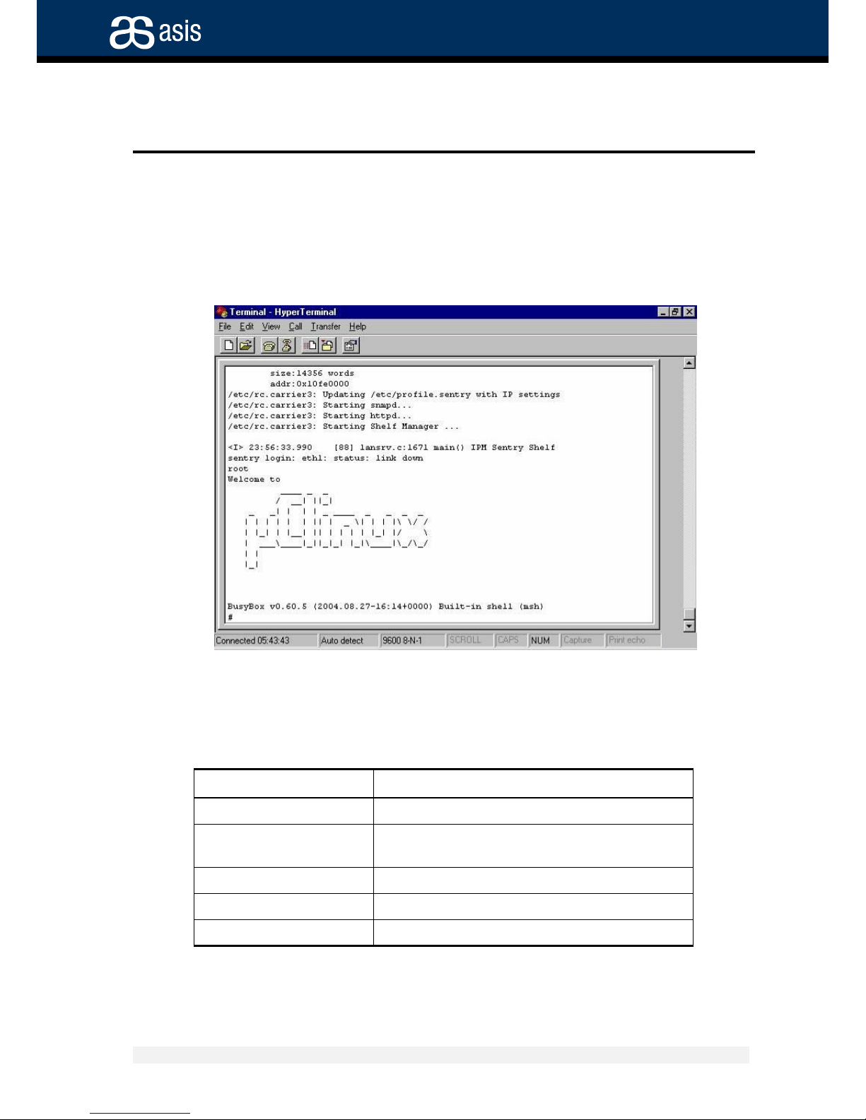
At start-up, the Shelf Management program requires user identification.
The default login name is: root with no password.
After login, the following screen will be displayed in the console (Terminal) window:
CLI (Command-line interface) Entry to the Management System
Commands can be typed after the “#” prompt. Commands to the Shelf Manager begin
with keyword “clia”.
For example:
# clia help
help on line commands
# ifconfig
get shelf IP address
# clia sensordata 86 48
get temperature data from board in slot 3
(on-board sensor 48)
# clia fans
Get data on fan health and speed
# clia sensor 86
Displays all sensors in board
# clia alarm 0
Clear all alarms
Page 24

Software Commands
Management Commands
ATCA Shelf Manager Board 24 Revision 1.2
Asis, the ATCA experts
There is a variety of commands for the shelf manager , which allow to control & monitor
number of parameters, including: temperature, fans tacho-meters, PEM sensors, etc'.
All of the commands can be found in the Shelf manager EIR - External Interface
Reference user manual , in order to retrieve this user manual please contact Asis
technical support department at Asis Support.
Page 25
Asis ATCA Shelf Acronyms
Management Commands
ATCA Shelf Manager Board 25 Revision 1.2
Asis, the ATCA experts
5 Asis ATCA Shelf Acronyms
Acronym
Meaning
ATCA
Advanced Telecom Computing Architecture
FRU
Field-Replaceable Unit
HS
Hot swap
PEM
Power Entry Module
IPMB
Intelligent Platform-Management Bus
IPMI
Intelligent Platform-Management Interface
RTM
Rear Transmission Module
NEBS
Network Equipment-Building Systems
ShMC
Shelf Manager board
ETSI
European Telecommunications Standards Institute
ANSI
American National Standards Institute
CE
"Conformité Européene" ("European Conformity")
FCC
Federal Communications Commission
UL
Underwriters Laboratories - safety standards
CFM
Cubic Feet per Minute – Airflow measurement unit
 Loading...