

Page 1

ASI
Automation Systems Interconnect, Inc
Innovative Interconnect and Interface Solutions
4 Channel Analog Converters with ModBus Interface
XCIO4 Series
The XCIO4 devices are analog converters, fully programmable through a PC application and with ModBus communication interface.
There are four different models:
• XCIO4VMB voltage converter
• XCIO4I
• XCIO4
• XCIO4TMB thermocouple converter
Each device has up to four independent channels, it is remotely configurable through the ModBus interface and in alternative with a
uUSB port with no need for additional power supply. The devices are fully programmable by means of CaburLab software application
or directly accessing the ModBus registers by means of a PLC. The on-board microprocessor manages all the peripherals and the
data transfers. High level precision is guaranteed by the 16 bit A/D to make the device suitable for process control, remote control
and building automation applications.
MB current con
RMB thermo resistance an
verter
d potentiometer converter
Page 2

ASI
Automation Systems Interconnect, Inc
Innovative Interconnect and Interface Solutions
4 Channel Analog Converters with ModBus Interface
ASICIO4 Series
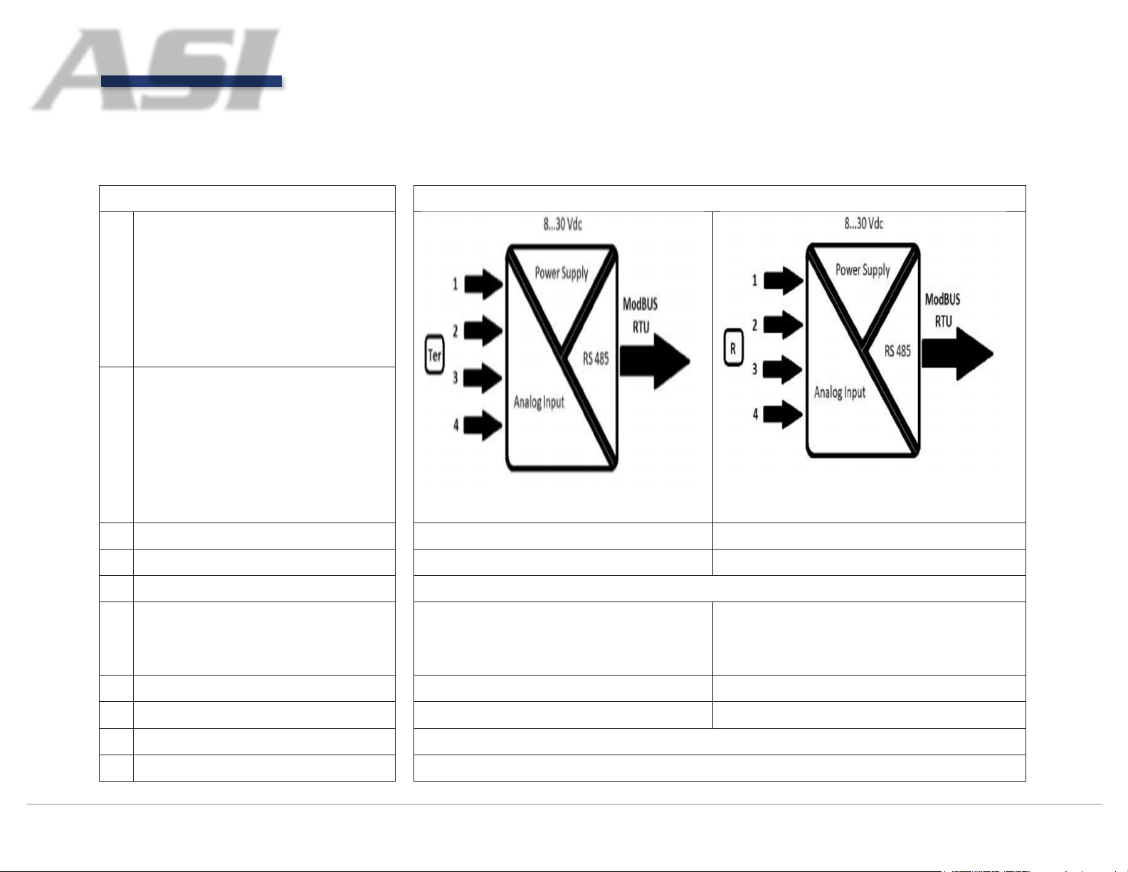
Technical Data:
Notes Schematics
(1) The device is powered by the USB
port when connected through USB.
In this case no communication over
ModBus is enabled. When both
USB and ModBus are connected
the ModBus interface has higher
priority
(2) Green led = the device is ON;
Red Led = alarm;
Yellow led 1 = ModBus TX activity;
Yellow led 2 = ModBus RX activity
Part Numbe
pe: CIO4VMB CIO4IMB
Ty
r: XCIO4VMB XCIO4IMB
INPUT DAT
Input Signal ±10 Vdc ±20 mA
Input Resist
Input Power ≤ 1W @ 24 Vdc
Number of I
MODBU
Communication
A
ance 1MΩ 56Ω
nputs 4
S PARAMETERS
Through ModBus RTU over RS485
Through uUSB for settings
Page 3

ASI
Automation Systems Interconnect, Inc
Innovative Interconnect and Interface Solutions
4 Channel Analog Converters with ModBus Interface
ASICIO4 Series
Settings Through CaburLab SW application
Linearity Error ±
Calibration
Thermal De
Baud Rate 1200÷230400 bps (configurable
Parity None, Odd,
Resolution
G
ENERAL TECHNICAL DATA
Supply Voltage 8…30 Vdc (protected ag
Operating Temperature -20...+70°C
S
torage Temperature -40...+85°
Humidity 0…90%
Isolation
Sampling Rate 100 ms
Signaling
Protection Degree IP20
Error ±0,05%
viation ±0,005%/°C
13 Bits
1500Vrms 1 minute (IN/OUT/Power)
0,1%
Even, Mark, Space
ainst polarity inversion)
C
Green LED IN / Red LED ALARM / Yellow LED TX / Yellow LED RX / Green LED x
4 (2)
Standards EN 61000-2, EN 61000-4
Pollution Degree 2
Overvoltage Category II
Connection
Enclosure Material UL94V-0 plastic material
Approximat
Dimensions W x D
Installation I
Terminal Type Pluggable 2.5 mm
e Weight 100g
nformation Vertical on DIN rail, spacing 5mm from adjacent components
2
screw connectors
x H 17.5x79x101mm
Page 4
ASI
Automation Systems Interconnect, Inc
Innovative Interconnect and Interface Solutions
4 Channel Analog Converters with ModBus Interface
ASICIO4 Series
Technical Data:
Notes Schematics
(1) The device is powered by the USB
port when connected through USB.
In this case no communication
over ModBus is enabled. When
both USB and ModBus are
connected the ModBus interface
has higher priority
(2) Green led = the device is ON;
Red Led = alarm;
Yellow led 1 = ModBus TX activity;
Yellow led 2 = ModBus RX activity
Part Number: XCIO4TMB XCIO4RMB
Type: CIO4T
INPUT DAT
Input Signal Thermocouple J, K, S, R, B, E, T,
Temperature range
Input Resistance 1MΩ 1MΩ
Input Power ≤ 1W @ 24 Vdc
Number of I
A
nputs 4
MB CIO4RMB
Thermo resistance (PT100_385,
PT500_385, PT1000_385, PT1000_392,
NI120, NIFE604,CU100,CU120),
potentiometers 0÷2kΩ
From -270 to +1820°C depending on TC From -200 a +850°C depending on TR
Page 5

ASI
Automation Systems Interconnect, Inc
Innovative Interconnect and Interface Solutions
Approximate Weight 100g
4 Channel Analog Converters with ModBus Interface
ASICIO4 Series
MODBUS PARAMETERS
Communication
Settings Through CaburLab SW application
Linearity Error ±0.1%
Calibration
Thermal Deviation ±0.005%/°C
Baud Rate 1200÷230400 bps (configurable
Parity None, Odd,
Resolution 13 Bits
GENERAL TECHNICAL DATA
Supply Voltage 8…30 Vdc (protected ag
Operating Temperature -20...+70°C
Storage Temperature -40...+85°C
Humidity 0…90%
Isolation 1500Vrms 1 minute (IN/OUT/Power)
Error ±0.05%
T
hrough ModBus RTU over RS485.
(1) Through uUSB for settings.
Even, Mark, Space
ainst polarity inversion)
Sampling Rate 100 ms
Signaling
Protection Degree IP20
Standards EN 61000-2, EN 61000-4
Pollution Degree 2
Overvoltage Category II
Connection Terminal Type Pluggable 2.5 mm
Enclosure Material UL94V-0 plastic material
Green LED IN / Red LED ALARM / Yellow LED TX / Yellow LED RX / Green LED x 4
(2)
2
screw connectors
Page 6

ASI
Automation Systems Interconnect, Inc
Innovative Interconnect and Interface Solutions
Dimensions W x D
x H 17.5x79x101mm
Installation I
nformation Vertical on DIN rail, spacing 5mm from adjacent components
CON
NECTION INSTRUCTIONS:
Inputs
Description
1 Nc Not Connected
2 Ch3+ CH3 + INPUT
3 Ch3- CH3 - INPUT
4 Nc Not Connected
5 Ch4+ CH4 + INPUT
6 Ch4- CH4 - INPUT
7 Nc Not Connected
8 Nc Not Connected
9 Vcc+ POWER SUPPLY (8...30VDC) +
10 Vcc- POWER SUPPLY (8...30VDC) -
11 Nc Not Connected
12 Ch1+ CH1 + INPUT
13 Ch1- CH1 - INPUT
14 Nc Not Connected
15 Ch2+ CH2 + INPUT
16 Ch2- CH2 - INPUT
17 RST RESET (CONNECT TO GND)
18 GND GROUND
19 D+ + MODBUS RS485
20 D- - MODBUS RS485
4 Channel Analog Converters with ModBus Interface
ASICIO4 Series
Page 7

ASI
Automation Systems Interconnect, Inc
Innovative Interconnect and Interface Solutions
Voltage Sensor Connection XCIO4VMB Current Sensor Connection XCIO4IMB
4 Channel Analog Converters with ModBus Interface
ASICIO4 Series
Potentiometer or Thermocouple Connection XCIO4TMB
Page 8

ASI
Automation Systems Interconnect, Inc
Innovative Interconnect and Interface Solutions
4 Channel Analog Converters with ModBus Interface
ASICIO4 Series
XCIO4RMB Module
Inputs
1 RTD3a SENSOR ACTIVATION INPUT CH3
2 RTD3b SENSOR READING INPUT CH3
3 RTD3c GROUND CH3
4 RTD4a SENSOR ACTIVATION INPUT CH4
5 RTD4b SENSOR READING INPUT CH4
6 RTD4c GROUND CH4
7 Nc Not Connected
8 Nc Not Connected
9 Vcc+ POWER SUPPLY (8...30VDC) +
10 Vcc- POWER SUPPLY (8...30VDC) -
11 RTD1a SENSOR ACTIVATION INPUT CH1
12 RTD1b SENSOR READING INPUT CH1
13 RTD1c GROUND CH1
Description
14 RTD2a SENSOR ACTIVATION INPUT CH2
15 RTD2b SENSOR READING INPUT CH2
16 RTD2c GROUND CH2
17 RST RESET (CONNECT TO GND)
18 GND GROUND
19 D+ + MODBUS RS485
20 D- - MODBUS RS485
Page 9

ASI
Automation Systems Interconnect, Inc
Innovative Interconnect and Interface Solutions
RTDxa Connecting Thermo-resistance and 2 or 3 wire Resistive Sensors XCIO4RMB
RTDxb
4 Channel Analog Converters with ModBus Interface
ASICIO4 Series
ACTIVE AND PASSIVE SENSORS
The XCIO4IMB device supports both active and passive sensors
Active
OPEN CIRCUIT LOGIC: The XCIO4RMB model is capable to send an alarm in case one of the wires of the sensor is interrupted. To
disable such alarm it is sufficient to connect a termination impedance on the channel.
When the channel is open the reading on the channel will be as follows: 2KΩ = 3200Ω; 500Ω = 500Ω; PT100/PT1000 = 916°C
Sensor Connection Passive
Sensor Connection
Page 10

ASI
Automation Systems Interconnect, Inc
Innovative Interconnect and Interface Solutions
4 Channel Analog Converters with ModBus Interface
ASICIO4 Series
LED SIGNALLING
LED GREEN
LED RED
LED YELLOW 1
LED Yellow2
MODBUS-RTU MAP RE
Baud Rate Table
Baud Rate
1200 1 No +0
2400 2 Odd +16
Base Code (decimal) Parity To be added to the Base Code
ON the device is powered
OFF the device is not powered
ON out of range device
OFF in range device
ON rx packet
OFF no rx packet
ON response packet ok
OFF no response packet
GISTERS
4800 3 Even +32
9600 4 Mark +48
14400 5 Space +64
19200 6 -
38400 7 -
57600 8 -
115200 9 -
230400 10 -
‐
‐
‐
‐
‐
Page 11

ASI
Automation Systems Interconnect, Inc
Innovative Interconnect and Interface Solutions
4 Channel Analog Converters with ModBus Interface
ASICIO4 Series
Input Type Table
Input Type (XCIOTMB) Input Type (XCIORMB) Code (decimal)
TCB PT100 0
TCE PT500 1
TCJ PT1000 2
TCK NI100 3
TCN NI120 4
TCR CU100 5
TCS CU120 6
TCT NIFE604 7
mV 2KOhm 8
- - - -
With the 06 function only one parameter can be written.
Ex: change the Modbus address from 01 to 02
5000Ohm 9
01 06 00 02 00 00 CRC CRC
Register which contains
the ModBus address
After a setting change the device must be reset (by means of a Coil command on the reg 01).
New ModBus address value
Page 12

ASI
Automation Systems Interconnect, Inc
Innovative Interconnect and Interface Solutions
A
A
A
A
A
A
A
A
A
A
A
A
A
A
A
A
A
A
4 Channel Analog Converters with ModBus Interface
ASICIO4 Series
REGISTER MAP
XCIO4VMB
FUNC TYPE IND. RANGE DESCRIPTION
03 HoldingRegister 1 (v. Baud Rate Table) RS485 baud rate (see v. Baud Rate Table)
03 HoldingRegister 2 Modbus address
03 SignedHoldingRegister 4
03 SignedHoldingRegister 5 Upper limit threshold input channel 1
03 SignedHoldingRegister 6
03 SignedHoldingRegister 7 Upper limit threshold input channel 2
03 SignedHoldingRegister 8
03 SignedHoldingRegister 9 Upper limit threshold input channel 3
03 SignedHoldingRegister 10
03 SignedHoldingRegister 11 Upper limit threshold input channel 4
03 HoldingRegister 14 Time constant IIR filter
04 InputRegister 1 HW/FW version
04 InputRegister 3 Status
04 InputRegister 4 BER Accumulator
04 SignedInputRegister 7
04 SignedInputRegister 8
04 SignedInputRegister 9
04 SignedInputRegister 10
04 SignedInputRegister 11
04 SignedInputRegister 12
04 SignedInputRegister 13
04 SignedInputRegister 14
04 FloatingInputRegister 17
04 FloatingInputRegister 19
04 FloatingInputRegister 21
04 FloatingInputRegister 23
04 FloatingInputRegister 25
04 FloatingInputRegister 27
04 FloatingInputRegister 29
04 FloatingInputRegister 31
03 SignedHoldingRegister 101
03 SignedHoldingRegister 102
-10000 mV / +10000 mV
-10000 mV / +10000 mV
-10000 mV / +10000 mV
-10000 mV / +10000 mV
Lower limit threshold input channel 1
Lower limit threshold input channel 2
Lower limit threshold input channel 3
Lower limit threshold input channel 4
nalog Input 1
nalog Input 2
nalog Input 3
nalog Input 4
nalog Input 1 (synchronized)
nalog Input 2 (synchronized)
nalog Input 3 (synchronized)
nalog Input 4 (synchronized)
nalog Input 1
nalog Input 2
nalog Input 3
nalog Input 4
nalog Input 1 (synchronized)
nalog Input 2 (synchronized)
nalog Input 3 (synchronized)
nalog Input 4 (synchronized)
nalog Input 1
nalog Input 2
Page 13

ASI
Automation Systems Interconnect, Inc
Innovative Interconnect and Interface Solutions
A
A
A
A
A
A
A
A
A
04 SignedInputRegister 10
A
nalog Input 4
4 Channel Analog Converters with ModBus Interface
ASICIO4 Series
03 SignedHoldingRegister 103
03 SignedHoldingRegister 104
03 FloatingHoldingRegister 107
03 FloatingHoldingRegister 109
03 FloatingHoldingRegister 111
03 FloatingHoldingRegister 113
05 Coil 1 Reset
05 Coil 2 BER counter reset (BiteErrorRate)
05 Coil 3 Read synchronization (on the 0 broadcast address)
05 Coil 4 Threshold enable
02 DiscreteInput 1 INIT Line state
XCIO4IMB
FUNC TYPE IND. RANGE DESCRIPTION
03 HoldingRegister 1 (v. Baud Rate Table) RS485 baud rate (see v. Baud Rate Table)
03 HoldingRegister 2 Modbus address
03 SignedHoldingRegister 4
03 SignedHoldingRegister 5 Upper limit threshold input channel 1
03 SignedHoldingRegister 6
03 SignedHoldingRegister 7 Upper limit threshold input channel 2
03 SignedHoldingRegister 8
03 SignedHoldingRegister 9 Upper limit threshold input channel 3
03 SignedHoldingRegister 10
03 SignedHoldingRegister 11 Upper limit threshold input channel 4
03 HoldingRegister 12 Input type (see table)
03 HoldingRegister 14 Time constant IIR filter
04 InputRegister 1 HW/FW version
04 InputRegister 3 Status
04 InputRegister 4 BER Accumulator
04 SignedInputRegister 7
04 SignedInputRegister 8
04 SignedInputRegister 9
-20000 mV / +20000 mV
-20000 mV / +20000 mV
-20000 mV / +20000 mV
-20000 mV / +20000 mV
nalog Input 3
nalog Input 4
nalog Input 1
nalog Input 2
nalog Input 3
nalog Input 4
Lower limit threshold input channel 1
Lower limit threshold input channel 2
Lower limit threshold input channel 3
Lower limit threshold input channel 4
nalog Input 1
nalog Input 2
nalog Input 3
Page 14

ASI
Automation Systems Interconnect, Inc
Innovative Interconnect and Interface Solutions
A
A
A
A
A
A
A
A
A
A
A
A
A
A
A
A
A
A
A
A
03 SignedHoldingRegister 6 -32000 mV / +32000 mV Lower limit threshold input channel 2
4 Channel Analog Converters with ModBus Interface
ASICIO4 Series
04 SignedInputRegister 11
04 SignedInputRegister 12
04 SignedInputRegister 13
04 SignedInputRegister 14
04 FloatingInputRegister 17
04 FloatingInputRegister 19
04 FloatingInputRegister 21
04 FloatingInputRegister 23
04 FloatingInputRegister 25
04 FloatingInputRegister 27
04 FloatingInputRegister 29
04 FloatingInputRegister 31
03 SignedHoldingRegister 101
03 SignedHoldingRegister 102
03 SignedHoldingRegister 103
03 SignedHoldingRegister 104
03 FloatingHoldingRegister 107
03 FloatingHoldingRegister 109
03 FloatingHoldingRegister 111
03 FloatingHoldingRegister 113
05 Coil 1 Reset
05 Coil 2 BER counter reset (BiteErrorRate)
05 Coil 3 Read synchronization (on the 0 broadcast address)
05 Coil 4 Threshold enable
02 DiscreteInput 1 INIT Line state
XCIO4TMB/XCIO4RMB
FUNC TYPE IND. RANGE DESCRIPTION
03 HoldingRegister 1 (v. Baud Rate Table) RS485 baud rate (see v. Baud Rate Table)
03 HoldingRegister 2 Modbus address
03 SignedHoldingRegister 4
03 SignedHoldingRegister 5 Upper limit threshold input channel 1
-32000 mV / +32000 mV
nalog Input 1 (synchronized)
nalog Input 2 (synchronized)
nalog Input 3 (synchronized)
nalog Input 4 (synchronized)
nalog Input 1
nalog Input 2
nalog Input 3
nalog Input 4
nalog Input 1 (synchronized)
nalog Input 2 (synchronized)
nalog Input 3 (synchronized)
nalog Input 4 (synchronized)
nalog Input 1
nalog Input 2
nalog Input 3
nalog Input 4
nalog Input 1
nalog Input 2
nalog Input 3
nalog Input 4
Lower limit threshold input channel 1
Page 15

ASI
Automation Systems Interconnect, Inc
Innovative Interconnect and Interface Solutions
A
A
A
A
A
A
A
A
A
A
A
A
A
A
A
A
A
A
A
03 SignedHoldingRegister 104
A
nalog Input 4
4 Channel Analog Converters with ModBus Interface
ASICIO4 Series
03 SignedHoldingRegister 7 Upper limit threshold input channel 2
03 SignedHoldingRegister 8
03 SignedHoldingRegister 9 Upper limit threshold input channel 3
03 SignedHoldingRegister 10
03 SignedHoldingRegister 11 Upper limit threshold input channel 4
03 HoldingRegister 12 Input type (see table)
03 HoldingRegister 14 Time constant IIR filter
04 InputRegister 1 HW/FW version
04 SignedInputRegister 2 Board temperature (Only for XCIO4TMB)
04 InputRegister 3 Status
04 InputRegister 4 BER Accumulator
04 SignedInputRegister 7
04 SignedInputRegister 8
04 SignedInputRegister 9
04 SignedInputRegister 10
04 SignedInputRegister 11
04 SignedInputRegister 12
04 SignedInputRegister 13
04 SignedInputRegister 14
04 SignedInputRegister 15 Board temperature (Only for XCIO4TMB)
04 FloatingInputRegister 17
04 FloatingInputRegister 19
04 FloatingInputRegister 21
04 FloatingInputRegister 23
04 FloatingInputRegister 25
04 FloatingInputRegister 27
04 FloatingInputRegister 29
04 FloatingInputRegister 31
04 FloatingInputRegister 33 Cold junction compensation equivalent voltage
03 SignedHoldingRegister 100 Board temperature (Only for XCIO4TMB)
03 SignedHoldingRegister 101
03 SignedHoldingRegister 102
03 SignedHoldingRegister 103
-32000 mV / +32000 mV
-32000 mV / +32000 mV
Lower limit threshold input channel 3
Lower limit threshold input channel 4
nalog Input 1
nalog Input 2
nalog Input 3
nalog Input 4
nalog Input 1 (synchronized)
nalog Input 2 (synchronized)
nalog Input 3 (synchronized)
nalog Input 4 (synchronized)
nalog Input 1
nalog Input 2
nalog Input 3
nalog Input 4
nalog Input 1 (synchronized)
nalog Input 2 (synchronized)
nalog Input 3 (synchronized)
nalog Input 4 (synchronized)
nalog Input 1
nalog Input 2
nalog Input 3
Page 16

ASI
Automation Systems Interconnect, Inc
Innovative Interconnect and Interface Solutions
A
A
A
A
4 Channel Analog Converters with ModBus Interface
ASICIO4 Series
03 FloatingHoldingRegister 107
03 FloatingHoldingRegister 109
03 FloatingHoldingRegister 111
03 FloatingHoldingRegister 113
05 Coil 1 Reset
05 Coil 2 BER counter reset (BiteErrorRate)
05 Coil 3 Read synchronization (on the 0 broadcast address)
05 Coil 4 Threshold enable
05 Coil 5 Cold junction compensation enable
02 DiscreteInput 1 INIT Line state
SCALE FUND:
When the value to read is out of range or no sensor is connected, the registers from 7 to 10 and the registers from 17 to 23 excluding
even numbers contain the following out of range values:
Sensor Out of range value (7 to 10 registers) Out of range value (17 to 23 registers)
RTD (PT100, PT500, PT1000, NI100,
NI120, CU100, CU120, NIFE604)
nalog Input 1
nalog Input 2
nalog Input 3
nalog Input 4
9160°C 916°C
2KOhm 32000 Ohm 3200 Ohm
500Ohm 5000 Ohm 500 Ohm
 Loading...