

Asian Express 15017 PPL User Manual
WARNING:
This product may contain small parts which
may pose a choking hazard to children.
FLIGHT INSTRUCTION MANUAL
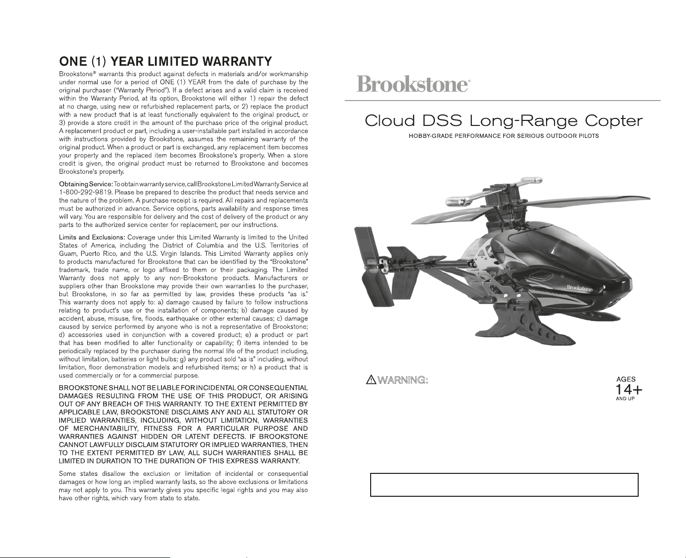
Thank you for purchasing the ClOUD DSS™ 2.4 G Wireless Outdoor Helicopter. Please read this instruction
booklet as it contains valuable information on how to properly fly and care for your helicopter.
WARNING: Never leave product charging unattended for extended periods of time. Always disconnect helicopter
from charger immediately after the helicopter is fully charged. Please refer to enclosed safety instructions.
Merrimack, New Hampshire USA 03054 • 800-846-3000 • www.Brookstone.com
796005
Colors and styles may slightly vary

PART REPLACEMENT INSTRUCTIONS
CONTENTS:
(1) Propeller blade x 2 (5) 2*8mm screws x 4
(2) Tail propeller blade x 1 (6) 2.3*5mm screws x 1
(3) Direction connecting rods x 2 (7) traning head x 1
(4) Connecting rods x 2
Cloud DSS PROPELLER SYSTEM
Your ClOUD DSS propeller system is a precision instrument that may need repair or replacement from time to time for optimal
flight function. Crash landing from high-speed aerial flights may cause damage to your ClOUD DSS propeller or propeller
connecting rods.
TROUBLESHOOTING:
If your ClOUD DSS loses its ability to fly correctly, please inspect the propeller system carefully for the following common
issues:
1. Replacing Connecting Rod and Direction Connecting Rod: The connecting rod is a small “handcuff” style device that
stabilizes the propellers. There are two connecting rods and two direction connecting rods on the propeller. Please see
Diagram 1.
If a connecting rod or direction rod is broken or missing simply replace it by “peeling” off the existing broken unit and
replacing it with a new one. You may have to use slight pressure when reattaching both ends of the new connecting rod.
Make sure that the new connecting rod is secured and locked in place. See Diagram 2. For changing connecting rod, make
sure there is no damage to the actual blade or arm that holds the connecting rod in place. If there is you must replace the
entire blade system.
2. Replacing Propeller: The propeller is subject to damage as you learn to properly fly and control your ClOUD DSS. If after a
crash your helicopter has loss of control or flies erratically you should carefully inspect your entire propeller system for any
sign of damage. Most common are: cracked or chipped blade, broken “connecting rod”, frozen balance bar (this is when the
balancing bar and blade are jammed and can not move freely up and down). To replace the propeller blades follow
diagrams 3 through 4.
3. Replacing Tail Propeller Blade: If after a crash your helicopter tail propeller blade is damaged, please replace it follow
diagrams 5 through 6.
4. Interchanging the Head: Your ClOUD DSS package includes a Training head. It is highly recommended for users who are
beginners to outdoor helicopters to practice initially with the Training head. It has been engineered using a more durable
material and is more likely to withstand crashes. Please changing the head follow diagrams 7 throught 10.
Replacing Connecting Rod and Direction Connecting Rod
Diagram 1
Replacing Damaged Propeller
Diagram 3 Diagram 4
Using a Phillips screwdriver turn
counter clockwise to remove the
propeller screw.
Remove the broken blade and
carefully replace with a new one,
and then screw on.
Replacing Damaged Tail Propeller
Diagram 5 Diagram 6
Using a Phillips screwdriver turn
counter clockwise to remove the tail
propeller screw.
Remove the broken tail blade
and carefully replace with a new
one, and then screw on.
Interchanging Training head
Diagram 7
Diagram 8
Using a Phillips screwdriver turn
rods on the propeller and two direction
connecting rods.
Diagram 2
Broken connecting rodThere are two propeller connecting
Proper connectionReplacing connecting rod
Broken connecting rod
9 10
counter clockwise to remove the head
bottom screw.
Diagram 9
Disconnect the head light power cord
inside and slide off the head.
Carefully snap off each side of the
head from the bar.
Diagram 10
Connect the head light power cord on
the new head and secure it by
reversing the previous steps.
(diagram 9-7)
 Loading...