

Page 1
Thales Navigation
471 El Camino Real
Santa Clara, CA USA 95050-4300
Phone and Fax Numbers
•Main
• Voice: +1 408-615-5100
• Fax: +1 408-615-5200
•Sales
• US: 1-800-922-2401
• International: +1 408-615-3970
• Fax: +1 408-615-5200
• Europe (France)
• Tel: +33 2 28 09 38 00
• Fax: +33 2 28 09 39 39
• South America
• Voice: +56 2 234 56 43
• Fax: +56 2 234 56 47
• Support
• US: 1 800-229-2400
• International: +1 408-615-3980
• Fax: +1 408-615-5200
Internet
• http://www.ashtech.com
• http://www.thalesnavigation.com
Page 2

Copyright Notice
Copyright © 2002 Thales Navigation. All rights reserved.
No part of this publication or the computer programs described in it may be reproduced, translated, stored in a retrieval system, or transmitted in any form or by any
means, electronic, mechanical photocopying, recording, or otherwise, without prior
written permission of Thales Navigation. Your rights with regard to this publication and
the computer programs are subject to the restrictions and limitiations imposed by the
copyright laws of the united States of America (“U.S.A”) and/or the jurisdiction in
which you are located.
For information on translations and distribution outside of the U.S.A please contact
Thales Navigation.
Printed in the United States of America.
Part Number: 630068, Revision D
March, 2002
Trademarks
G12, Evaluate, Edge, Strobe, SSRadio, Sensor II, Receiver Communication
Software, and the Ashtech logo are trademarks of Thales Navigation. All other
product and brand names are trademarks or registered trademarks of their respective
holders.
ii G12 GPS OEM Board & Sensor Reference Manual
Page 3

Chapter 1. General Information . . . . . . . . . . . . . . . . . . . . . . . . . . . . . . . . . . . . . 1
Overview . . . . . . . . . . . . . . . . . . . . . . . . . . . . . . . . . . . . . . . . . . . . . . . . . . . . 1
Functional Description . . . . . . . . . . . . . . . . . . . . . . . . . . . . . . . . . . . . . . . . . . 2
Hardware Description . . . . . . . . . . . . . . . . . . . . . . . . . . . . . . . . . . . . . . . . . . . 3
Power Connections . . . . . . . . . . . . . . . . . . . . . . . . . . . . . . . . . . . . . . . . . . . .5
Interfaces to External Equipment . . . . . . . . . . . . . . . . . . . . . . . . . . . . . . . . . .9
Power Requirements . . . . . . . . . . . . . . . . . . . . . . . . . . . . . . . . . . . . . . . . . . 10
Environmental Specifications . . . . . . . . . . . . . . . . . . . . . . . . . . . . . . . . . . . .10
RF Connections . . . . . . . . . . . . . . . . . . . . . . . . . . . . . . . . . . . . . . . . . . . . . .10
Radio Interference . . . . . . . . . . . . . . . . . . . . . . . . . . . . . . . . . . . . . . . . . . . . 11
Receiver Options . . . . . . . . . . . . . . . . . . . . . . . . . . . . . . . . . . . . . . . . . . . . . 11
G12-L . . . . . . . . . . . . . . . . . . . . . . . . . . . . . . . . . . . . . . . . . . . . . . . . . . . . . . 14
G12 Evaluation Kits . . . . . . . . . . . . . . . . . . . . . . . . . . . . . . . . . . . . . . . . . . . 14
Firmware Upgrades . . . . . . . . . . . . . . . . . . . . . . . . . . . . . . . . . . . . . . . . . . . 15
Chapter 2. Getting Started. . . . . . . . . . . . . . . . . . . . . . . . . . . . . . . . . . . . . . . . 19
Connecting to the G12 . . . . . . . . . . . . . . . . . . . . . . . . . . . . . . . . . . . . . . . . . 20
Power . . . . . . . . . . . . . . . . . . . . . . . . . . . . . . . . . . . . . . . . . . . . . . . . . . 20
Antenna . . . . . . . . . . . . . . . . . . . . . . . . . . . . . . . . . . . . . . . . . . . . . . . . 21
Important Default Parameters . . . . . . . . . . . . . . . . . . . . . . . . . . . . . . . . . . .22
Communication Port Setup. . . . . . . . . . . . . . . . . . . . . . . . . . . . . . . . . . 22
Data Output Options. . . . . . . . . . . . . . . . . . . . . . . . . . . . . . . . . . . . . . . 22
Initial Operating Instructions . . . . . . . . . . . . . . . . . . . . . . . . . . . . . . . . . . . . . 22
Chapter 3. Operation . . . . . . . . . . . . . . . . . . . . . . . . . . . . . . . . . . . . . . . . . . . . 25
System Setup . . . . . . . . . . . . . . . . . . . . . . . . . . . . . . . . . . . . . . . . . . . . . . . . 25
Power-Up . . . . . . . . . . . . . . . . . . . . . . . . . . . . . . . . . . . . . . . . . . . . . . . 25
Message Formats . . . . . . . . . . . . . . . . . . . . . . . . . . . . . . . . . . . . . . . . . . . .26
G12 Input Messages . . . . . . . . . . . . . . . . . . . . . . . . . . . . . . . . . . . . . . 26
iii
Page 4

G12 Message Output . . . . . . . . . . . . . . . . . . . . . . . . . . . . . . . . . . . . . . 27
Serial Port Configuration . . . . . . . . . . . . . . . . . . . . . . . . . . . . . . . . . . . . . . .27
Satellite Tracking . . . . . . . . . . . . . . . . . . . . . . . . . . . . . . . . . . . . . . . . . . . . . 28
Parameter Settings and Status . . . . . . . . . . . . . . . . . . . . . . . . . . . . . . . . . .28
Saving Parameter Settings . . . . . . . . . . . . . . . . . . . . . . . . . . . . . . . . . . 30
Watchdog Timer . . . . . . . . . . . . . . . . . . . . . . . . . . . . . . . . . . . . . . . . . . 30
Position Modes . . . . . . . . . . . . . . . . . . . . . . . . . . . . . . . . . . . . . . . . . . . 30
Fixed Altitude Modes . . . . . . . . . . . . . . . . . . . . . . . . . . . . . . . . . . . . . . 31
Geoid Model . . . . . . . . . . . . . . . . . . . . . . . . . . . . . . . . . . . . . . . . . . . . . 32
Ionospheric Model . . . . . . . . . . . . . . . . . . . . . . . . . . . . . . . . . . . . . . . . 32
Magnetic Variation Model . . . . . . . . . . . . . . . . . . . . . . . . . . . . . . . . . . . 33
Setting Antenna Position . . . . . . . . . . . . . . . . . . . . . . . . . . . . . . . . . . . 33
NMEA Outputs . . . . . . . . . . . . . . . . . . . . . . . . . . . . . . . . . . . . . . . . . . . 33
Raw Data Output (Optional) . . . . . . . . . . . . . . . . . . . . . . . . . . . . . . . . . 34
Differential Operation (Optional) . . . . . . . . . . . . . . . . . . . . . . . . . . . . . . . . . .35
General . . . . . . . . . . . . . . . . . . . . . . . . . . . . . . . . . . . . . . . . . . . . . . . . . 35
Sources of Error . . . . . . . . . . . . . . . . . . . . . . . . . . . . . . . . . . . . . . . . . . 37
RTCM Messages . . . . . . . . . . . . . . . . . . . . . . . . . . . . . . . . . . . . . . . . . 38
RTCM 104 Format, Version 2.2 . . . . . . . . . . . . . . . . . . . . . . . . . . . . . . 39
Photogrammetry / Event Marking (Optional) . . . . . . . . . . . . . . . . . . . . . . . .40
Time Tagging the Shutter Signal . . . . . . . . . . . . . . . . . . . . . . . . . . . . . 41
Closed-Loop Technique (Advanced Trigger) . . . . . . . . . . . . . . . . . . . . 42
Timing Pulse & Measurement Strobe (Optional) . . . . . . . . . . . . . . . . . . . . .42
10 HZ and 20 HZ Outputs . . . . . . . . . . . . . . . . . . . . . . . . . . . . . . . . . . . . . .44
RAIM Algorithm . . . . . . . . . . . . . . . . . . . . . . . . . . . . . . . . . . . . . . . . . . . . . .45
Chapter 4. Command/Response Formats . . . . . . . . . . . . . . . . . . . . . . . . . . . . 47
Receiver Commands . . . . . . . . . . . . . . . . . . . . . . . . . . . . . . . . . . . . . . . . . . 49
AIM: RAIM Availability—Extended Memory G12 Only . . . . . . . . . . . . . 53
ALT: Ellipsoidal Height . . . . . . . . . . . . . . . . . . . . . . . . . . . . . . . . . . . . . 54
CLK: Clock Status. . . . . . . . . . . . . . . . . . . . . . . . . . . . . . . . . . . . . . . . . 55
CRR: Code Correlator Mode . . . . . . . . . . . . . . . . . . . . . . . . . . . . . . . . 56
CTS: Handshaking Protocol . . . . . . . . . . . . . . . . . . . . . . . . . . . . . . . . . 57
DAP: Doppler Averaging Interval . . . . . . . . . . . . . . . . . . . . . . . . . . . . . 58
DFO: Remote Station Status . . . . . . . . . . . . . . . . . . . . . . . . . . . . . . . . 59
DSY: Daisy Chain Communications Mode . . . . . . . . . . . . . . . . . . . . . . 60
DTM: Set Reference Datum . . . . . . . . . . . . . . . . . . . . . . . . . . . . . . . . . 61
DUG: GPS/UTC Time Difference . . . . . . . . . . . . . . . . . . . . . . . . . . . . . 65
ERM: Set Position Error Mask Values . . . . . . . . . . . . . . . . . . . . . . . . . 66
FIX: Fixed Altitude Mode . . . . . . . . . . . . . . . . . . . . . . . . . . . . . . . . . . . 67
FUM: Fix UTM Zone . . . . . . . . . . . . . . . . . . . . . . . . . . . . . . . . . . . . . . . 68
FZN: Select Fixed UTM Zone . . . . . . . . . . . . . . . . . . . . . . . . . . . . . . . . 68
GDC: 3-D Position in User-defined Grid Coordinates. . . . . . . . . . . . . . 69
iv G12 OEM Board & Sensor Reference Manual
Page 5

GRD: Datum-to-Grid (Map Projection)— Extended Memory G12 Only 71
HDP: HDOP Mask Value . . . . . . . . . . . . . . . . . . . . . . . . . . . . . . . . . . . 71
INI: Initialize the Receiver . . . . . . . . . . . . . . . . . . . . . . . . . . . . . . . . . . . 72
ION: Ionospheric and Tropospheric Modeling . . . . . . . . . . . . . . . . . . . 73
LPS: Third-order Loop Tracking Parameters . . . . . . . . . . . . . . . . . . . . 74
LTZ: Local Time Zone. . . . . . . . . . . . . . . . . . . . . . . . . . . . . . . . . . . . . . 77
MEM: Results of Last Memory Test . . . . . . . . . . . . . . . . . . . . . . . . . . . 77
PAR: Query General Receiver Parameters . . . . . . . . . . . . . . . . . . . . . 78
PDP: PDOP Mask Value. . . . . . . . . . . . . . . . . . . . . . . . . . . . . . . . . . . . 81
PEM: Position Elevation Mask Value . . . . . . . . . . . . . . . . . . . . . . . . . . 81
PHE: Photogrammetry Edge Mode. . . . . . . . . . . . . . . . . . . . . . . . . . . . 81
PMD: Position Mode . . . . . . . . . . . . . . . . . . . . . . . . . . . . . . . . . . . . . . . 82
POP: Position and Raw Data Update Rate. . . . . . . . . . . . . . . . . . . . . . 84
PPO: Point Positioning . . . . . . . . . . . . . . . . . . . . . . . . . . . . . . . . . . . . . 85
POS: 3-D Antenna Position . . . . . . . . . . . . . . . . . . . . . . . . . . . . . . . . . 86
PPS: Pulse Per Second . . . . . . . . . . . . . . . . . . . . . . . . . . . . . . . . . . . . 87
PRR: Extended-Memory— Extended Memory G12 Only . . . . . . . . . . . 88
PRT: Serial Port Baud Rate . . . . . . . . . . . . . . . . . . . . . . . . . . . . . . . . . 89
PSM: Navigation Mode Filtering . . . . . . . . . . . . . . . . . . . . . . . . . . . . . . 90
RID: Receiver Identification Parameters (Format 1) . . . . . . . . . . . . . . . 90
RIO: Receiver Identification Parameters (Format 2). . . . . . . . . . . . . . . 93
RSO: Receiver Serial Options . . . . . . . . . . . . . . . . . . . . . . . . . . . . . . . 95
RST: Restore Default Parameters . . . . . . . . . . . . . . . . . . . . . . . . . . . . 95
SAV: Save Parameter Settings. . . . . . . . . . . . . . . . . . . . . . . . . . . . . . . 95
SEM: Secondary Elevation Mask . . . . . . . . . . . . . . . . . . . . . . . . . . . . . 96
SMI: Code Measurement Smoothing . . . . . . . . . . . . . . . . . . . . . . . . . . 97
SNR: Set Signal-to-Noise Ratio . . . . . . . . . . . . . . . . . . . . . . . . . . . . . . 98
SPD: Serial Port Baud Rate . . . . . . . . . . . . . . . . . . . . . . . . . . . . . . . . . 99
STA: Satellite Tracking Status . . . . . . . . . . . . . . . . . . . . . . . . . . . . . . 100
STB: Measurement Strobe Output . . . . . . . . . . . . . . . . . . . . . . . . . . . 100
SUI: Satellite Usage Indicator. . . . . . . . . . . . . . . . . . . . . . . . . . . . . . . 101
UDD: User-defined Datum . . . . . . . . . . . . . . . . . . . . . . . . . . . . . . . . . 102
UDG: User-Defined Datum-to-Grid, Extended Memory G12 Only . . . 106
USE: Satellites for Acquisition . . . . . . . . . . . . . . . . . . . . . . . . . . . . . . 110
USP: Satellites Used in Position Computation . . . . . . . . . . . . . . . . . . 110
UTS: Synchronize with GPS Time . . . . . . . . . . . . . . . . . . . . . . . . . . . 111
VDP: VDOP Mask. . . . . . . . . . . . . . . . . . . . . . . . . . . . . . . . . . . . . . . . 111
Raw Data Commands . . . . . . . . . . . . . . . . . . . . . . . . . . . . . . . . . . . . . . . .113
Message Structure . . . . . . . . . . . . . . . . . . . . . . . . . . . . . . . . . . . . . . . 116
Checksum. . . . . . . . . . . . . . . . . . . . . . . . . . . . . . . . . . . . . . . . . . . . . . 116
CT1: Combined Measurement/Position Data (Format 1) . . . . . . . . . . 117
CT2: Combined Measurement/Position Data (Format 2) . . . . . . . . . . 118
CT3: Combined Measurement/Position Data (Format 3) . . . . . . . . . . 120
v
Page 6

ELM: Elevation Mask for Raw Measurements Outputs . . . . . . . . . . . 122
MBN: Raw Measurements (Ashtech Type 2 Data Structure) . . . . . . . 123
MCA: Raw Measurements (Ashtech Type 3 Data Structure) . . . . . . . 125
MCM: Missile Application Condensed Measurement Record (MACM) - G12
HDMA Users Only . . . . . . . . . . . . . . . . . . . . . . . . . . . . . . . . . . . . . . 128
MSV: Minimum Satellites for Raw Measurement Output . . . . . . . . . . 131
PBN: Raw Position Data. . . . . . . . . . . . . . . . . . . . . . . . . . . . . . . . . . . 132
RAW: Setting Query Command . . . . . . . . . . . . . . . . . . . . . . . . . . . . . 133
RCI: Set Output Interval for Raw Messages. . . . . . . . . . . . . . . . . . . . 134
SAL: Satellite Almanac Data. . . . . . . . . . . . . . . . . . . . . . . . . . . . . . . . 135
SIT: Site Name for Observation Session . . . . . . . . . . . . . . . . . . . . . . 136
SNV: Satellite Ephemeris Data. . . . . . . . . . . . . . . . . . . . . . . . . . . . . . 137
NMEA Commands . . . . . . . . . . . . . . . . . . . . . . . . . . . . . . . . . . . . . . . . . . .139
Message Structure . . . . . . . . . . . . . . . . . . . . . . . . . . . . . . . . . . . . . . . 141
NME: Enable/Disable All NMEA Messages . . . . . . . . . . . . . . . . . . . . 142
AIM: Receiver Autonomous Integrity Monitor — Ext. Mem. G12 Only 143
CRT: Cartesian Coordinates Message . . . . . . . . . . . . . . . . . . . . . . . . 144
GDC: Grid Coordinates. . . . . . . . . . . . . . . . . . . . . . . . . . . . . . . . . . . . 146
GGA: 3-D GPS Position . . . . . . . . . . . . . . . . . . . . . . . . . . . . . . . . . . . 148
GLL: 2-D Position . . . . . . . . . . . . . . . . . . . . . . . . . . . . . . . . . . . . . . . . 151
GRS: Satellite Range Residuals. . . . . . . . . . . . . . . . . . . . . . . . . . . . . 152
GSA: DOP and Active Satellites . . . . . . . . . . . . . . . . . . . . . . . . . . . . . 154
GSN: Satellite PRN Number and Signal Strength . . . . . . . . . . . . . . . 156
GST: Pseudo-Range Error Statistics . . . . . . . . . . . . . . . . . . . . . . . . . 158
GSV: Satellites in View . . . . . . . . . . . . . . . . . . . . . . . . . . . . . . . . . . . . 160
LTN: Position Output Latency. . . . . . . . . . . . . . . . . . . . . . . . . . . . . . . 162
MSG: Differential Base Station Data . . . . . . . . . . . . . . . . . . . . . . . . . 164
PER: Global Output Interval . . . . . . . . . . . . . . . . . . . . . . . . . . . . . . . . 172
POS: Position Message . . . . . . . . . . . . . . . . . . . . . . . . . . . . . . . . . . . 172
RMC: Recommended Minimum Course . . . . . . . . . . . . . . . . . . . . . . . 174
RRE: Satellite Range Residuals and Position Error . . . . . . . . . . . . . . 177
SAT: Comprehensive Satellite Tracking Data . . . . . . . . . . . . . . . . . . 178
TCM: Differential Remote Station Status . . . . . . . . . . . . . . . . . . . . . . 181
TTT: Photogrammetry Event Marker . . . . . . . . . . . . . . . . . . . . . . . . . 183
UTM: Universal Transverse Mercator (UTM) - Ext. Mem. G12 Only . 184
VTG: Course and Speed Over Ground. . . . . . . . . . . . . . . . . . . . . . . . 186
ZDA: Time and Date . . . . . . . . . . . . . . . . . . . . . . . . . . . . . . . . . . . . . . 188
RTCM Commands . . . . . . . . . . . . . . . . . . . . . . . . . . . . . . . . . . . . . . . . . . .190
AUT: Automatic Differential Mode . . . . . . . . . . . . . . . . . . . . . . . . . . . 191
BAS: Set Receiver in Differential Base Station Mode. . . . . . . . . . . . . 191
IOD: Ephemeris Data Update Rate for RTCM Base Station . . . . . . . 192
MAX: Maximum Age Threshold for Differential Corrections . . . . . . . . 192
MSG: Define RTCM Type 16 Message . . . . . . . . . . . . . . . . . . . . . . . 193
vi G12 OEM Board & Sensor Reference Manual
Page 7

OFF: Disable Differential Operation . . . . . . . . . . . . . . . . . . . . . . . . . . 193
REM: Set Receiver in Differential Remote Station Mode . . . . . . . . . . 193
RTC: Query RTCM Operating Parameters and Status. . . . . . . . . . . . 194
SEQ: Verify RTCM Message Sequence. . . . . . . . . . . . . . . . . . . . . . . 196
SPD: Baud Rate for RTCM Message Output . . . . . . . . . . . . . . . . . . . 197
STH: Differential Base Station Health. . . . . . . . . . . . . . . . . . . . . . . . . 198
STI: Differential Base/Remote Station ID . . . . . . . . . . . . . . . . . . . . . . 198
TYP: Enable/Disable Output of RTCM Message Types . . . . . . . . . . . 199
Appendix A. G12 and Sensor II: Differences and Compatibility . . . . . . . . . . 201
Appendix B. Floating Point Data Representation . . . . . . . . . . . . . . . . . . . . . 205
Sign Bit Field. . . . . . . . . . . . . . . . . . . . . . . . . . . . . . . . . . . . . . . . . . . . 205
Exponent Field . . . . . . . . . . . . . . . . . . . . . . . . . . . . . . . . . . . . . . . . . . 205
Fraction Field . . . . . . . . . . . . . . . . . . . . . . . . . . . . . . . . . . . . . . . . . . . 205
The Represented Value . . . . . . . . . . . . . . . . . . . . . . . . . . . . . . . . . . . 206
Single-Precision Float . . . . . . . . . . . . . . . . . . . . . . . . . . . . . . . . . .206
Double-Precision Float . . . . . . . . . . . . . . . . . . . . . . . . . . . . . . . . .207
Appendix C. Global Product Support . . . . . . . . . . . . . . . . . . . . . . . . . . . . . . 209
Solutions for Common Problems . . . . . . . . . . . . . . . . . . . . . . . . . . . . . . . .210
Corporate Web Page . . . . . . . . . . . . . . . . . . . . . . . . . . . . . . . . . . . . . . . . .211
Repair Centers . . . . . . . . . . . . . . . . . . . . . . . . . . . . . . . . . . . . . . . . . . . . . .212
Glossary . . . . . . . . . . . . . . . . . . . . . . . . . . . . . . . . . . . . . . . . . . . . . . . . . . . . . .213
Index . . . . . . . . . . . . . . . . . . . . . . . . . . . . . . . . . . . . . . . . . . . . . . . . . . . . . . . . .227
vii
Page 8

viii G12 OEM Board & Sensor Reference Manual
Page 9

Figure 1.1. G12 GPS Board Dimensions. . . . . . . . . . . . . . . . . . . . . . . . . . . . . . .5
Figure 1.2. J301 Pin Assignments . . . . . . . . . . . . . . . . . . . . . . . . . . . . . . . . . . . . 6
Figure 1.3. External Equipment Interfacing Diagram. . . . . . . . . . . . . . . . . . . . . .9
Figure 1.4. G12 Sensor Evaluation Kit . . . . . . . . . . . . . . . . . . . . . . . . . . . . . . .16
Figure 1.5. G12 Sensor Power-I/O Connections . . . . . . . . . . . . . . . . . . . . . . . .17
Figure 1.6. G12 OEM Board Evaluation Kit . . . . . . . . . . . . . . . . . . . . . . . . . . . . 18
Figure 2.1. G12 Board Connections . . . . . . . . . . . . . . . . . . . . . . . . . . . . . . . . .20
Figure 3.1. RTCM Base Station System . . . . . . . . . . . . . . . . . . . . . . . . . . . . . .36
Figure 3.2. RTCM Remote System . . . . . . . . . . . . . . . . . . . . . . . . . . . . . . . . . . 37
Figure 3.3. GPS Epochs . . . . . . . . . . . . . . . . . . . . . . . . . . . . . . . . . . . . . . . . . . 40
Figure 3.4. PPS Synchronization. . . . . . . . . . . . . . . . . . . . . . . . . . . . . . . . . . . .42
Figure 3.5. Timing Pulse Characteristics . . . . . . . . . . . . . . . . . . . . . . . . . . . . . . 43
Figure 3.6. Relationship of GPS Time in PRN Record to 1PPS Pulse . . . . . . . 44
Figure 4.1. SEM Mask Zone . . . . . . . . . . . . . . . . . . . . . . . . . . . . . . . . . . . . . . . 97
Figure 4.2. Rotation and Translation Between WGS72 and WGS84 . . . . . . .105
ix
Page 10

x G12 GPS OEM Board & Sensor Reference Manual
Page 11

Table 1.1. G12 Specifications . . . . . . . . . . . . . . . . . . . . . . . . . . . . . . . . . . . . . . 1
Table 1.2. J301 Pin Assignments . . . . . . . . . . . . . . . . . . . . . . . . . . . . . . . . . . . 6
Table 1.3. Power Requirements . . . . . . . . . . . . . . . . . . . . . . . . . . . . . . . . . . . 10
Table 1.4. $PASHR,RIO Message Format . . . . . . . . . . . . . . . . . . . . . . . . . . . 11
Table 1.5. G12 Option Descriptions . . . . . . . . . . . . . . . . . . . . . . . . . . . . . . . . 12
Table 1.6. Typical RIO Response . . . . . . . . . . . . . . . . . . . . . . . . . . . . . . . . . . 13
Table 2.1. Antenna Requirements . . . . . . . . . . . . . . . . . . . . . . . . . . . . . . . . . 21
Table 2.2. Antenna LNA Requirements . . . . . . . . . . . . . . . . . . . . . . . . . . . . . 21
Table 2.3. G12 Communication Parameters. . . . . . . . . . . . . . . . . . . . . . . . . . 22
Table 3.1. RTCM Format . . . . . . . . . . . . . . . . . . . . . . . . . . . . . . . . . . . . . . . . 39
Table 4.1. Command Parameter Symbols . . . . . . . . . . . . . . . . . . . . . . . . . . . 48
Table 4.2. Query Command Structure . . . . . . . . . . . . . . . . . . . . . . . . . . . . . . 50
Table 4.3. Receiver Commands . . . . . . . . . . . . . . . . . . . . . . . . . . . . . . . . . . . 50
Table 4.4. AIM Response Message . . . . . . . . . . . . . . . . . . . . . . . . . . . . . . . . 54
Table 4.5. $PASHQ,CLK Format . . . . . . . . . . . . . . . . . . . . . . . . . . . . . . . . . . 55
Table 4.6. $PASHR,CRR Format . . . . . . . . . . . . . . . . . . . . . . . . . . . . . . . . . . 56
Table 4.7. Typical CRR Message . . . . . . . . . . . . . . . . . . . . . . . . . . . . . . . . . . 57
Table 4.8. $PASHR,CTS Format . . . . . . . . . . . . . . . . . . . . . . . . . . . . . . . . . . 58
Table 4.9. Typical CTS Response Message. . . . . . . . . . . . . . . . . . . . . . . . . . 58
Table 4.10. $PASHR,DAP Format . . . . . . . . . . . . . . . . . . . . . . . . . . . . . . . . . . 59
Table 4.11. $PASHR,DFO Structure . . . . . . . . . . . . . . . . . . . . . . . . . . . . . . . . 60
Table 4.12. Daisy Chain Commands . . . . . . . . . . . . . . . . . . . . . . . . . . . . . . . . 61
Table 4.13. Predefined Datums and Associated Reference Ellipsoids. . . . . . . 62
Table 4.14. Predefined Ellipsoids . . . . . . . . . . . . . . . . . . . . . . . . . . . . . . . . . . . 64
Table 4.15. $PASHR,DUG Binary Data String Format . . . . . . . . . . . . . . . . . . . 65
Table 4.16. GDC Message Structure . . . . . . . . . . . . . . . . . . . . . . . . . . . . . . . . 69
Table 4.17. Typical GDC Response Message . . . . . . . . . . . . . . . . . . . . . . . . . 70
Table 4.18. Serial Port Baud Rate Codes. . . . . . . . . . . . . . . . . . . . . . . . . . . . . 72
Table 4.19. Memory Reset Codes . . . . . . . . . . . . . . . . . . . . . . . . . . . . . . . . . . 72
xi
Page 12

Table 4.20. $PASHR,ION Format . . . . . . . . . . . . . . . . . . . . . . . . . . . . . . . . . . . 73
Table 4.21. $PASHR,LPS Format. . . . . . . . . . . . . . . . . . . . . . . . . . . . . . . . . . . 75
Table 4.22. Typical LPS Response Message . . . . . . . . . . . . . . . . . . . . . . . . . . 76
Table 4.23. Format of Response for $PASHQ,MEM . . . . . . . . . . . . . . . . . . . . 78
Table 4.24. PAR Response Format . . . . . . . . . . . . . . . . . . . . . . . . . . . . . . . . . 79
Table 4.25. $PASHR,PHE Format . . . . . . . . . . . . . . . . . . . . . . . . . . . . . . . . . . 82
Table 4.26. Typical PHE Response Message. . . . . . . . . . . . . . . . . . . . . . . . . . 82
Table 4.27. $PASHR,PHE Format . . . . . . . . . . . . . . . . . . . . . . . . . . . . . . . . . . 84
Table 4.28. Typical POP Response Message . . . . . . . . . . . . . . . . . . . . . . . . . 84
Table 4.29. PPO Parameter Table . . . . . . . . . . . . . . . . . . . . . . . . . . . . . . . . . . 85
Table 4.30. $PASHR,POS Message Format . . . . . . . . . . . . . . . . . . . . . . . . . . 86
Table 4.31. $PASHR,PPS Message Format. . . . . . . . . . . . . . . . . . . . . . . . . . . 88
Table 4.32. $PASHR,PRT Message Format. . . . . . . . . . . . . . . . . . . . . . . . . . . 89
Table 4.33. G12 Baud Rate Codes . . . . . . . . . . . . . . . . . . . . . . . . . . . . . . . . . . 89
Table 4.34. $PASHS,PSM Fields . . . . . . . . . . . . . . . . . . . . . . . . . . . . . . . . . . . 90
Table 4.35. $PASHR,RID Fields . . . . . . . . . . . . . . . . . . . . . . . . . . . . . . . . . . . . 91
Table 4.36. Available G12 Options . . . . . . . . . . . . . . . . . . . . . . . . . . . . . . . . . . 91
Table 4.37. $PASHR,RID Fields . . . . . . . . . . . . . . . . . . . . . . . . . . . . . . . . . . . . 92
Table 4.38. RIO Structure . . . . . . . . . . . . . . . . . . . . . . . . . . . . . . . . . . . . . . . . . 93
Table 4.39. $PASHR,RIO Fields. . . . . . . . . . . . . . . . . . . . . . . . . . . . . . . . . . . . 94
Table 4.40. RSO Format . . . . . . . . . . . . . . . . . . . . . . . . . . . . . . . . . . . . . . . . . . 95
Table 4.41. G12 Baud Rate Codes . . . . . . . . . . . . . . . . . . . . . . . . . . . . . . . . . . 99
Table 4.42. STA Response Format. . . . . . . . . . . . . . . . . . . . . . . . . . . . . . . . . 100
Table 4.43. $PASHR,STB Response Structure . . . . . . . . . . . . . . . . . . . . . . . 101
Table 4.44. MCA Good/Bad Flags and SAT Messages When SUI is ON . . . 101
Table 4.45. User-defined Datum Parameters . . . . . . . . . . . . . . . . . . . . . . . . . 103
Table 4.46. Ellipsoid Parameters for WGS72 and WGS84. . . . . . . . . . . . . . . 104
Table 4.47. UDG Structure for Equatorial Mercator . . . . . . . . . . . . . . . . . . . . 106
Table 4.48. UDG Structure for Transverse Mercator . . . . . . . . . . . . . . . . . . . 106
Table 4.49. UDG Structure for Oblique Mercator . . . . . . . . . . . . . . . . . . . . . . 107
Table 4.50. UDG Structure for Stereographic (Polar and Oblique). . . . . . . . . 107
Table 4.51. UDG Structure for Lambert Conformal SPC83 (2 Std.Parallels) . 107
Table 4.52. UDG Structure for Lambert Conformal Conic for SPC27. . . . . . . 108
Table 4.53. UDG Structure for Transverse Mercator for SPC27. . . . . . . . . . . 109
Table 4.54. UDG Structure for Transverse Mercator SPC27 Alaska Zones 2-9109
Table 4.55. Raw Data Commands . . . . . . . . . . . . . . . . . . . . . . . . . . . . . . . . . 113
Table 4.56. $PASHR,CT1 Data String . . . . . . . . . . . . . . . . . . . . . . . . . . . . . . 117
Table 4.57. $PASHR,CT2 Data String . . . . . . . . . . . . . . . . . . . . . . . . . . . . . . 119
Table 4.58. $PASHR,CT3 Data String . . . . . . . . . . . . . . . . . . . . . . . . . . . . . . 121
Table 4.59. $PASHS,RAW,MBN Output Rate Range and Increments. . . . . . 123
Table 4.60. $PASHR,MBN Data String, Ashtech Type 2 . . . . . . . . . . . . . . . . 124
Table 4.61. MBN Warning Flag Format . . . . . . . . . . . . . . . . . . . . . . . . . . . . . 125
Table 4.62. $PASHR,MCA Data String. . . . . . . . . . . . . . . . . . . . . . . . . . . . . . 126
xii G12 OEM Board & Sensor Reference Manual
Page 13

Table 4.63. MACM Data String . . . . . . . . . . . . . . . . . . . . . . . . . . . . . . . . . . . . 130
Table 7.64. PBN Data String. . . . . . . . . . . . . . . . . . . . . . . . . . . . . . . . . . . . . . 132
Table 4.65. $PASHQ,RAW Response Parameters . . . . . . . . . . . . . . . . . . . . 133
Table 4.66. Raw Data Update Rate Options and Settings . . . . . . . . . . . . . . . 134
Table 4.67. $PASHR,SAL Data String . . . . . . . . . . . . . . . . . . . . . . . . . . . . . . 136
Table 4.68. $PASHQ,SNV Response Structure . . . . . . . . . . . . . . . . . . . . . . . 137
Table 4.69. NMEA Data Message Commands . . . . . . . . . . . . . . . . . . . . . . . . 139
Table 4.70. RAIM Response Message Structure . . . . . . . . . . . . . . . . . . . . . . 144
Table 4.71. $PASHR,CRT Message Format . . . . . . . . . . . . . . . . . . . . . . . . . 145
Table 4.72. GDC Response Message Format . . . . . . . . . . . . . . . . . . . . . . . . 146
Table 4.73. Typical GDC Message . . . . . . . . . . . . . . . . . . . . . . . . . . . . . . . . . 147
Table 4.74. $GPGGA Message Format . . . . . . . . . . . . . . . . . . . . . . . . . . . . . 149
Table 4.75. Typical GGA Message . . . . . . . . . . . . . . . . . . . . . . . . . . . . . . . . . 150
Table 4.76. $GPGLL Message Format . . . . . . . . . . . . . . . . . . . . . . . . . . . . . . 151
Table 4.77. Typical GLL Message . . . . . . . . . . . . . . . . . . . . . . . . . . . . . . . . . 152
Table 4.78. $GPGRS Message Format . . . . . . . . . . . . . . . . . . . . . . . . . . . . . 153
Table 4.79. Typical GRS Message . . . . . . . . . . . . . . . . . . . . . . . . . . . . . . . . . 154
Table 4.80. $GPGSA Message Format . . . . . . . . . . . . . . . . . . . . . . . . . . . . . 155
Table 4.81. Typical $GPGSA Message . . . . . . . . . . . . . . . . . . . . . . . . . . . . . 155
Table 4.82. $GPGSN Message Format . . . . . . . . . . . . . . . . . . . . . . . . . . . . . 157
Table 4.83. Typical GSN Message . . . . . . . . . . . . . . . . . . . . . . . . . . . . . . . . . 157
Table 4.84. $GPGST Message Format. . . . . . . . . . . . . . . . . . . . . . . . . . . . . . 159
Table 4.85. Typical GST Message . . . . . . . . . . . . . . . . . . . . . . . . . . . . . . . . . 160
Table 4.86. $GPGSV Message Format . . . . . . . . . . . . . . . . . . . . . . . . . . . . . 161
Table 4.87. Typical GSV Message . . . . . . . . . . . . . . . . . . . . . . . . . . . . . . . . . 162
Table 4.88. $PASHR,LTN Message Format . . . . . . . . . . . . . . . . . . . . . . . . . . 163
Table 4.89. $PASHQ,LTN Query Response. . . . . . . . . . . . . . . . . . . . . . . . . . 163
Table 4.90. Common MSG Data Fields . . . . . . . . . . . . . . . . . . . . . . . . . . . . . 166
Table 4.91. Remainder of Type 1 . . . . . . . . . . . . . . . . . . . . . . . . . . . . . . . . . . 166
Table 4.92. Remainder of Type 2 Message . . . . . . . . . . . . . . . . . . . . . . . . . . 166
Table 4.93. Remainder of Type 3 Message . . . . . . . . . . . . . . . . . . . . . . . . . . 167
Table 4.94. Remainder of Type 16 Message . . . . . . . . . . . . . . . . . . . . . . . . . 167
Table 4.95. Typical MSG message for RTCM Type 01 . . . . . . . . . . . . . . . . . 167
Table 4.96. Typical MSG message for RTCM Type 2 . . . . . . . . . . . . . . . . . . 169
Table 4.97. Typical MSG Message for RTCM Type 3 . . . . . . . . . . . . . . . . . . 171
Table 4.98. Typical MSG Message For RTCM Type 16 . . . . . . . . . . . . . . . . . 171
Table 4.99. POS Response Structure. . . . . . . . . . . . . . . . . . . . . . . . . . . . . . . 173
Table 4.100. Typical POS Response Message . . . . . . . . . . . . . . . . . . . . . . . . 174
Table 4.101. $GPRMC Message Format . . . . . . . . . . . . . . . . . . . . . . . . . . . . . 175
Table 4.102. Typical RMC Message . . . . . . . . . . . . . . . . . . . . . . . . . . . . . . . . . 176
Table 4.103. $GPRRE Message Format . . . . . . . . . . . . . . . . . . . . . . . . . . . . . 177
Table 4.104. Typical RRE Message . . . . . . . . . . . . . . . . . . . . . . . . . . . . . . . . . 178
Table 4.105. $PASHR,SAT Message Format. . . . . . . . . . . . . . . . . . . . . . . . . . 179
xiii
Page 14

Table 4.106. Typical SAT Message . . . . . . . . . . . . . . . . . . . . . . . . . . . . . . . . . 181
Table 4.107. $PASHS,NME,TCM Response Structure . . . . . . . . . . . . . . . . . . 182
Table 4.108. Typical TCM Message . . . . . . . . . . . . . . . . . . . . . . . . . . . . . . . . . 183
Table 4.109. $PASHR,TTT Message Format . . . . . . . . . . . . . . . . . . . . . . . . . . 184
Table 4.110. Example TTT Response Message. . . . . . . . . . . . . . . . . . . . . . . . 184
Table 4.111. $PASHR,UTM Message Format . . . . . . . . . . . . . . . . . . . . . . . . . 185
Table 4.112. Typical UTM Message . . . . . . . . . . . . . . . . . . . . . . . . . . . . . . . . . 186
Table 4.113. $GPVTG Response Structure . . . . . . . . . . . . . . . . . . . . . . . . . . . 187
Table 4.114. Typical VTG Message . . . . . . . . . . . . . . . . . . . . . . . . . . . . . . . . . 188
Table 4.115. $GPZDA Message Format. . . . . . . . . . . . . . . . . . . . . . . . . . . . . . 189
Table 4.116. Typical ZDA Message . . . . . . . . . . . . . . . . . . . . . . . . . . . . . . . . . 189
Table 4.117. RTCM Response Message Commands. . . . . . . . . . . . . . . . . . . . 190
Table 4.118. RTC Response Format . . . . . . . . . . . . . . . . . . . . . . . . . . . . . . . . 194
Table 4.119. Available Output Bit Rates for RTCM Messages . . . . . . . . . . . . . 197
Table 4.120. $PASHS,RTC Health of Reference . . . . . . . . . . . . . . . . . . . . . . . 198
Table 4.121. $PASHS,RTC,TYP Message Types . . . . . . . . . . . . . . . . . . . . . . 199
Table A.1. G12 and Sensor II Connector Pin Configurations . . . . . . . . . . . . 202
Table B.1. Single-Precision Format. . . . . . . . . . . . . . . . . . . . . . . . . . . . . . . . 206
Table B.2 Double-Precision Format . . . . . . . . . . . . . . . . . . . . . . . . . . . . . . . 207
Table C.1. GPS Product Information . . . . . . . . . . . . . . . . . . . . . . . . . . . . . . . 210
xiv G12 OEM Board & Sensor Reference Manual
Page 15
The G12 GPS receiver processes signals from the Global Positioning System
(GPS) satellite constellation to provide real-time position, velocity, and time
measurements. The G12 uses twelve discrete parallel channels for Coarse/
Acquisition (C/A) code-phase (pseudo-range) measurements and carrier phase
measurements on the L1 (1575.42 Mhz) band. The G12 receives satellite signals
through an L-band antenna and an external low-noise amplifier (LNA). The G12 is
designed for stand-alone and differential GPS (DGPS) operation; it can operate
as a base (reference) station or a remote (rover) station, providing or using real-
time differential GPS corrections in RTCM SC-104 format (Version 2.2).
This chapter describes G12 hardware and functionality, describes the RF
interface connector and the power/input/output connector, and lists specifications
and power requirements.
Table 1.1. G12 Specifications
POSITION ACCURACY (DGPS)
Horizontal CEP 40.0 cm
Horizontal (95%) 90.0 cm
Vertical (95%) 160.0 cm
TIME TO FIRST FIX (TTFF)
Re-acquisition 2 seconds
Hot Start 11 seconds
Warm Start 35 seconds
Cold Start 45 seconds
General Information 1
Page 16
Table 1.1. G12 Specifications (Continued)
PHYSICAL SPECIFICATIONS
Size Board: 2.300” x 4.250” (± 0.005); 107.95 mm x 57 mm (± 0.13)
Weight Board: 2.8 oz
Humidity 95% non-condensing
Shock RTCA DO-160C - op/crash safety:
Vibration • MIL-STD-810E/Category 10, Minimum Integrity Test - General
Acceleration 20 G
Maximum speed 1,000 knots
Maximum altitude 60,000 ft
Higher altitudes and velocities may be available under validated export license.
Sensor: 178 mm x 105 mm x 52 mm
Sensor: 1 lb 4 oz
• Operational — ± 6 G in X, Y, or Z axis
• Non-operational — ± 15 G in X, Y, or Z axis
(HDMA version only)
• DO 160C - NMB
• Performance:
• 5G sine sweep
• 20 - 400 Hz
• 20 hours/axis
Upon application of power, the G12 runs a built-in self test of its internal memory,
and thereafter periodically self-tests various functions during normal operation.
Test results are stored for output on command. After self test, the G12 initializes
its battery-backed RAM. If the battery-backed RAM fails self-test (due, for
example, to a low battery backup condition), the G12 clears and reports the loss
of stored data, then initializes its 12 channels and begins searching for all
satellites within the field of view of its antenna.
The G12 can track all GPS satellites (also called space vehicles or SVs) as
specified in the Navstar GPS Space Segment/Navigation User Interfaces, ICDGPS-200, Revision B. All 32 satellite PRN (pseudo-random noise) code numbers
are programmed into the G12’s firmware. There are 24 satellites in the GPS
constellation. As it acquires (locks on to) each satellite, the G12 notes the time
2 G12 OEM Board & Sensor Reference Manual
Page 17

and collects almanac and ephemeris data for each orbiting satellite and stores
this information in battery-backed memory.
• When tracking one satellite, the G12 gets a time reference from that
satellite’s clock.
• When tracking three satellites, the G12 computes and time-tags the
horizontal position (2D) and velocity of its antenna. Input of an initial
position estimate is not required. When it receives an appropriate
command message from controller equipment through one of its serial
communication ports, the G12 sends the results of its computations to the
designated port.
• With four locked satellites, the G12 determines three-dimensional position
and velocity. Stand-alone position accuracy is 3 meters Circular Error
Probable (CEP) when Position Dilution of Precision (PDOP) is less than 4;
velocity accuracy is 0.1 meter per second. Accuracy levels for position and
velocity are subject to the US Government policy of Selective Availability
(SA). When the G12 is operating in differential mode, position accuracy
improves to better than 1.0 m CEP.
The G12 can compute up to 20 independent measurements per cycle (20 Hz),
with no interpolation or extrapolation from previous solutions. Position and
velocity computations are performed simultaneously using all the satellites in
view. The G12 uses instantaneous doppler values from four satellites to compute
dynamic speed, allowing velocity computations to be made independent of the
last position fix. All measurements are referenced to the WGS-84 (World
Geodetic System-1984) ellipsoid model.
The G12 features 12-channel/12-Satellite All-In-View operation; each of up to 12
visible satellites can be assigned to a discrete channel for continuous tracking.
Each satellite broadcasts almanac and ephemeris information every 30 seconds;
this information is recorded in G12 memory automatically.
General Information
The G12 is available in two versions. The G12 Sensor contains the G12 receiver
board, a wide range power supply, and a back-up battery for internal memory in a
rugged aluminum enclosure. It can accept input voltage levels from 9 to 36 VDC,
and typical power consumption is approximately 2.2 watts. Power drain on the
back-up battery is typically less than 0.3 mA when external power is applied to the
board, and 1 mA otherwise.
The G12 OEM Board is the G12 GPS receiver board assembly without the
enclosure, back-up battery, or wide range power supply. It requires a regulated
input voltage of 5 VDC (±5%); typical power consumption is approximately 1.8
watts. User-entered parameters can be maintained in the G12 internal memory by
General Information 3
Page 18

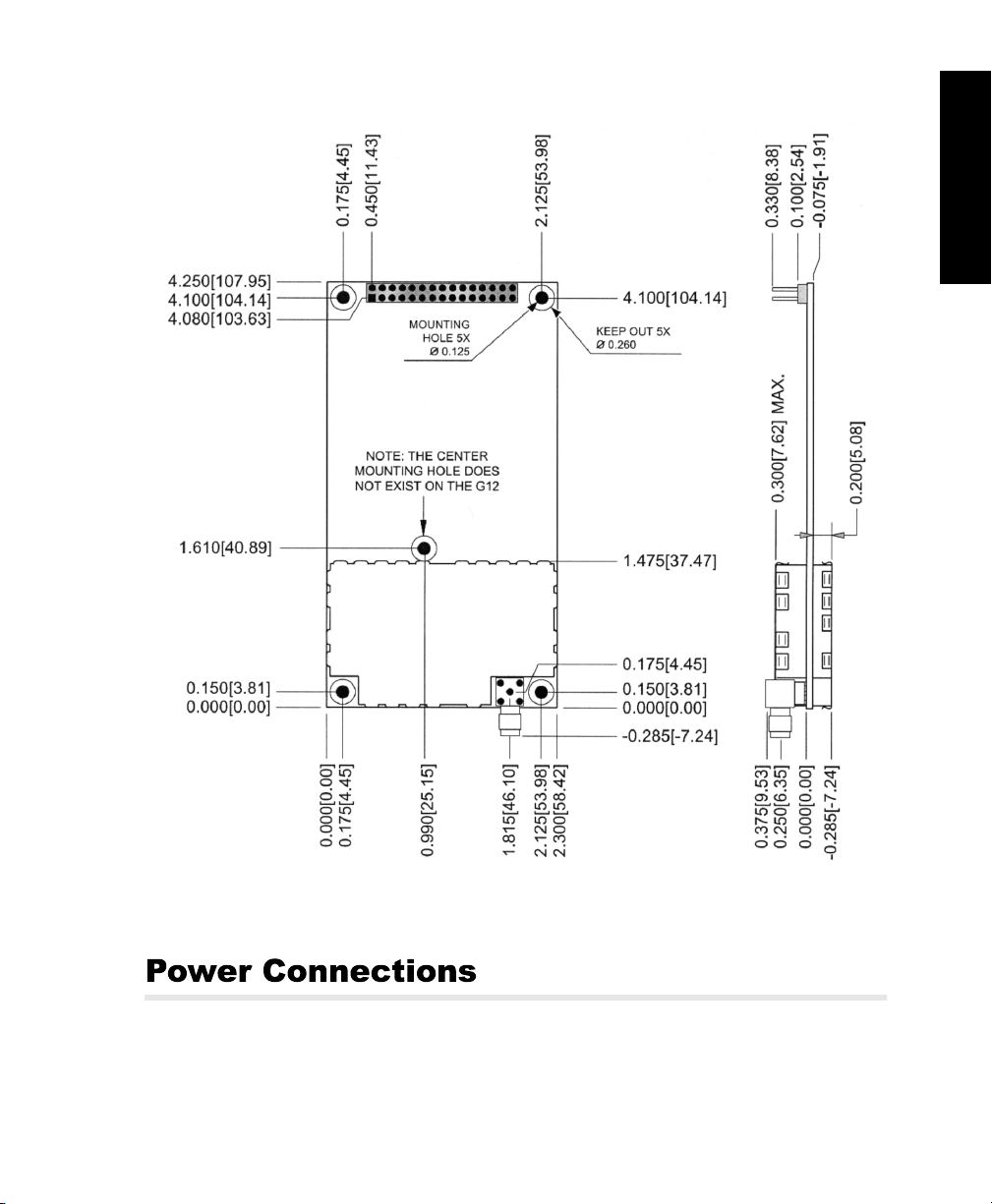
connecting a 3 to 3½-volt external battery to the appropriate pins on J301. The
physical dimensions of the G12 GPS board are shown in Figure 1.1.
From a functional point of view, the G12 receiver consists of two major sections:
The radio frequency (RF) section, and the digital section, where the signals from
the GPS satellites are processed.
Both versions of the G12 have two RS-232 input/output (I/O) ports capable of
two-way communication with external equipment, and a coaxial RF port for the
antenna.
The RF section receives satellite signals from the GPS antenna and LNA through
a coaxial cable, and also supplies power to the antenna/LNA through the cable,
eliminating the necessity of a separate power cable for the antenna. Total power
consumption (including the LNA) is approximately 2.1 watts for the board and 2.5
watts for the sensor.
The twelve-pin connector (J101) on the side of the board is intended for factory use only.
The G12 uses a standard SMA connector for RF input (Figure 1.1). A straight-up
OSX RF connector is also available as an option.
A two-color LED is mounted on the G12: Red indicates the power status, and
green indicates the number of satellites locked (e.g., 4 green flashes indicate 4
satellites locked).
4 G12 OEM Board & Sensor Reference Manual
Page 19
General Information
Figure 1.1. G12 GPS Board Dimensions
All power and input/output connections are made at the J301 connector. J301is a
30-pin male dual inline (15 x 2) header connector. It provides a host of useful
connections in addition to power and I/O, including a connection for an external
General Information 5
Page 20
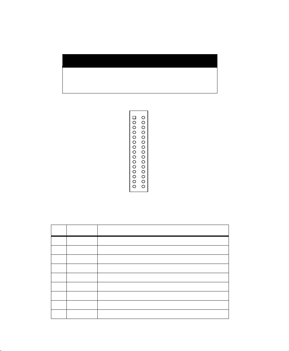
LED, a connection for battery-backup for RAM maintenance, an input for manual
hardware reset, an output for a TTL-level timing pulse, a photogrammetry timetag input, and a measurement strobe output. Figure 1.2 lists the pin assignments
for J301.
CAUTION
To avoid damage to the G12 OEM board, ensure that pin 1 of the connecting cable is attached to pin 1 on J301 as indicated in the drawing.
In addition, the power source should be turned off while connecting
or disconnecting cables to or from the J301 connector.
J301
1
GND
TXDA
RXDA
GND
TXDB
RXDB
+5V
BATT_IN
MAN_RES
GND
LED_RED
MSTR_OUT
VARF_OUT
PHOTO_IN
RESERVED FOR INTERNAL USE
3
5
7
9
11
13
15
17
19
21
23
25
27
29
2
CTSA
4
RTSA
6
RESERVED FOR INTERNAL USE
8
CTSB
10
RTSB
12
RESERVED FOR INTERNAL USE
14
+5V
16
RESERVED FOR INTERNAL USE
18
1PPS_OUT
20
GND
22
LED_GRN
24
GND
26
GND
28
RESERVED FOR INTERNAL USE
30
RESERVED FOR INTERNAL USE
Figure 1.2. J301 Pin Assignments
Table 1.2. J301 Pin Assignments
Pin Code Description
01 GND Ground for serial Port A
02 CTSA RS-232 Port A clear to send
03 TXDA RS-232 Port A transmit data
04 RTSA RS-232 Port A request to send
05 RXDA RS-232 Port A receive data
06 DX Ashtech internal use only (leave floating)
07 GND Ground for serial Port B
08 CTSB RS-232 Port B clear to send
09 TXDB RS-232 Port B transmit data
6 G12 OEM Board & Sensor Reference Manual
Page 21

Table 1.2. J301 Pin Assignments (Continued)
Pin Code Description
10 RTSB RS-232 Port B request to send
11 RXDB RS-232 Port B receive data
12 FSX Ashtech internal use only (leave floating)
13 +5V +5 VDC input
14 +5V +5 VDC input
15 BATT_IN 2.5-3.5 volt battery backup for memory and real-time clock
16 CLKRX Ashtech internal use only (leave floating)
17 MAN_RES* Connect to ground for manual hardware reset
18 1PPS_OUT 1 pps TTL output synchronized to GPS time
19 GND G12 chassis common ground
20 GND G12 chassis common ground
21 LED_RED
22 LED_GRN
23 MSTR_OUT Measurement strobe output
24 GND G12 chassis common ground
25 VARF_OUT Variable frequency output
26 GND G12 chassis common ground
27 PHOTO_IN Photogrammetry pulse input
28 FSR Ashtech internal use only (leave floating)
29 SERBLEN* Ashtech internal use only (leave floating)
30 DR Ashtech internal use only (leave floating)
External LED control output (3.3 Volts through 100
External LED control output (3.3 Volts through 100
W)
W)
General Information
CAUTION
• If pin 15 (BATT_IN) is not used, it should be connected to ground (GND)
• If pin 17 (MAN_RES*) is not used, it should be left open
• If pin 17 (MAN_RES*) is used, it can be pulled to ground (GND) using a
switch, or driven to ground with an open-collector gate.
General Information 7
Page 22

WARNING!
To save user-entered parameters between power cycles, connect the external
battery to the corresponding input pins on the J301 connector and set the
SAV parameter to Y.
8 G12 OEM Board & Sensor Reference Manual
Page 23
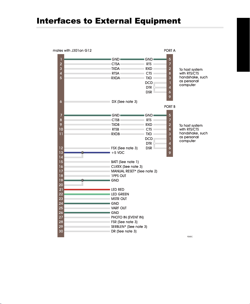
Figure 1.3 shows G12 interfacing connections.
General Information
Figure 1.3. External Equipment Interfacing Diagram
Figure 1.3 Notes
1. BATT is a control line normally connected to 3 VDC, or ground if not used.
General Information 9
Page 24
2. Manual reset (MAN_RES*) should be left unconnected if unused. Manual
reset should be activated by a switch or open collector gate.
3. Magellan internal use only (leave floating).
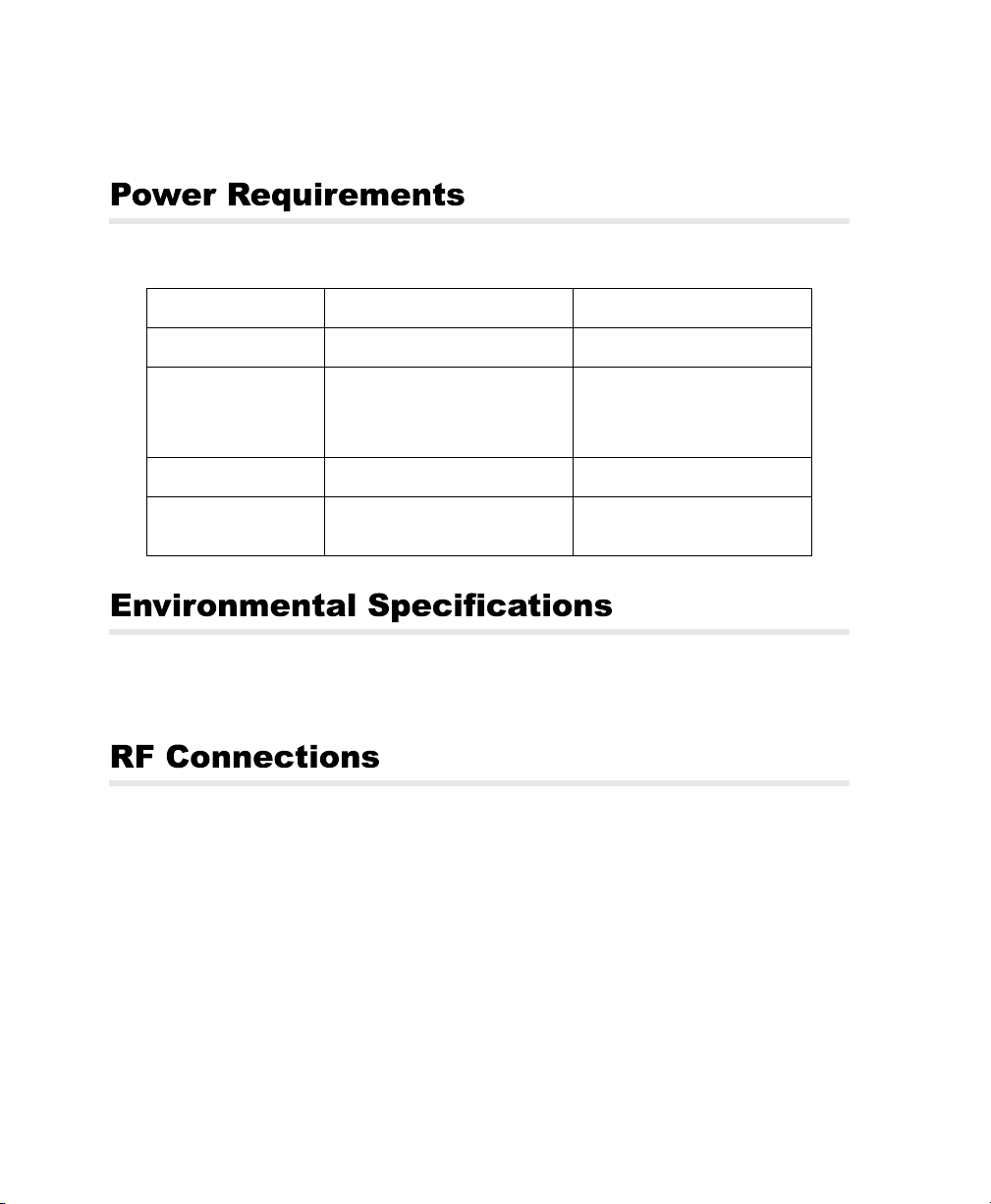
Table 1.3. Power Requirements
Requirement Board Sensor
DC voltage
Power Consumption
(typical)
External wiring
Internal battery drain
5 volts DC, regulated ± 5% 9 - 36 VDC
1.8 watts
(2.1 watts with antenna/LNA)
Current draw: 360 mA @ 5 VDC
30 gauge (minimum) 30 gauge (minimum)
mA (without 5 VDC applied)
1
mA (with 5 VDC applied)
0.3
2.2 watts
(2.5 watts with antenna/LNA)
Current draw: 245 mA @ 9 VDC
61 mA @ 36 VDC
1
mA (without 9-36 VDC applied)
mA (with 9-36 VDC applied)
0.3
The operating temperature range of the G12 is -30°C to +70°C; storage
temperature range is -30°C to +85°C.
A 50-ohm coaxial cable and an LNA are required for impedance matching
between the G12 RF connector and the GPS antenna. The G12 board’s RF
connector is a standard SMA female connector (TNC on the G12 Sensor, see
Figure 1.4). The SMA connector shell is connected to common ground on the
G12 board. The SMA center pin provides +4.8 VDC (to power the LNA) and
accepts 1575 MHz RF input from the antenna; the RF and DC signals share the
same path. The gain of the antenna LNA minus the loss of the cable is in between
20 and 30 dB.
10 G12 OEM Board & Sensor Reference Manual
Page 25
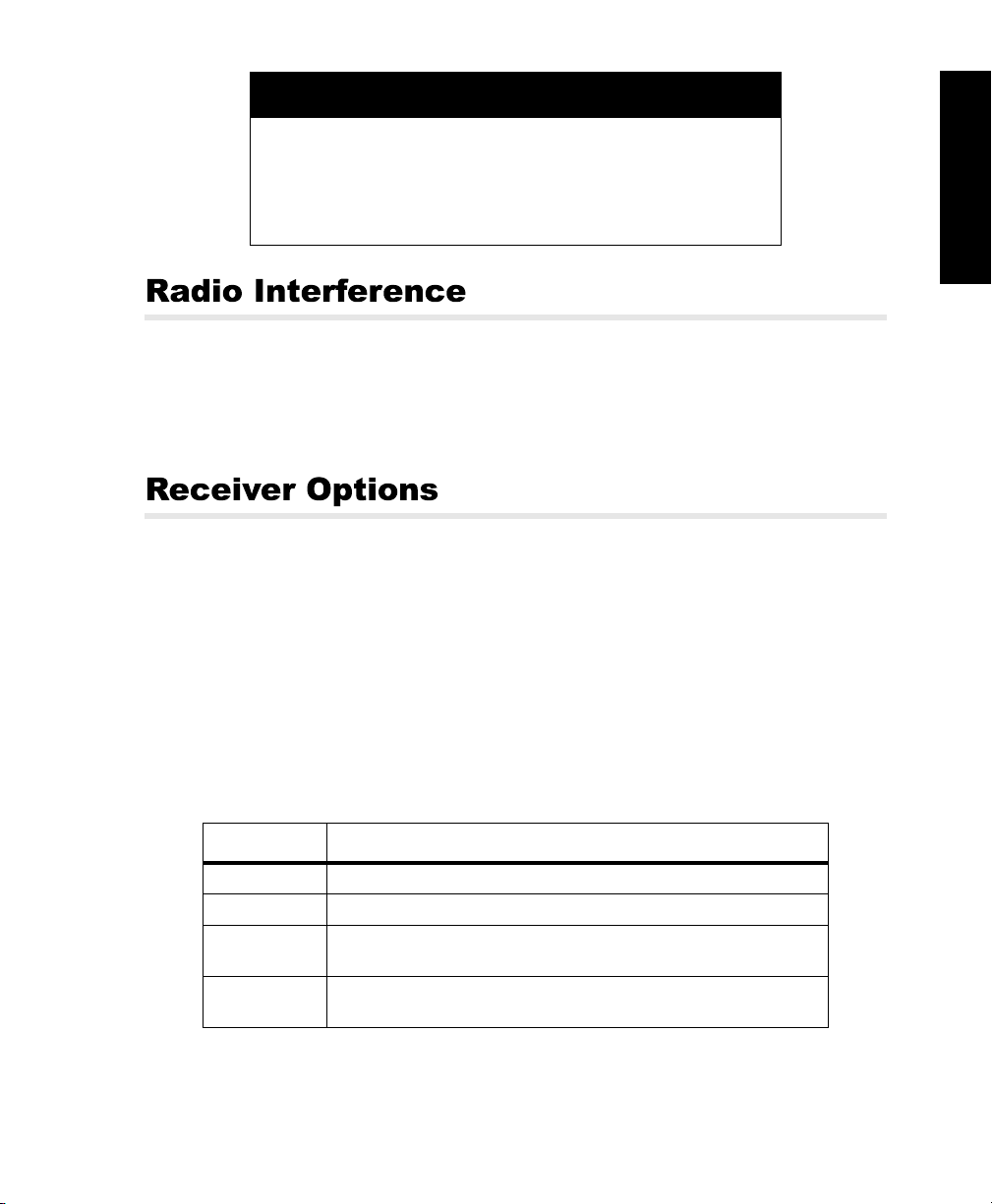
CAUTION
The G12 may be damaged if the SMA center pin is not isolated from
DC ground. Provide a DC block between the center pin and ground.
The block should have the following characteristics:
• VSWR 1.15 maximum at 1575 MHz
• Insertion loss 0.2 dB maximum
• Maximum voltage 5 VDC
Some radio transmitters and receivers, such as FM radios, can interfere with the
operation of GPS receivers. Magellan recommends that you verify that nearby
hand-held or mobile communications devices do not interfere with your GPS
receivers before setting up your project.
The G12 has a number of available options. The options that are set in the
receiver will determine which commands and features you can use. For example,
if the photogrammetry option is not installed, you will not be able to use the
$PASHS,TTT command to output event time tags from the serial port.
The command $PASHQ,RIO queries for the receiver’s configuration. The
response message includes version numbers for the processor and channel
firmware, a list of installed options, and the receiver’s serial identification number.
The response is output in the format shown below:
$PASHR,RIO,f1,f2,f3,f4,f5*cc
General Information
Table 1.4. $PASHR,RIO Message Format
Field Description
f1 Receiver name (maximum 10 characters)
f2 Main processor firmware version (maximum 10 characters)
f3 Channel Firmware version (maximum 10 characters). If not applicable,
this field is empty
f4 Option setting (maximum 42 characters). ASCII characters represent
General Information 11
installed options. For option definitions, see Table 1.5
Page 26
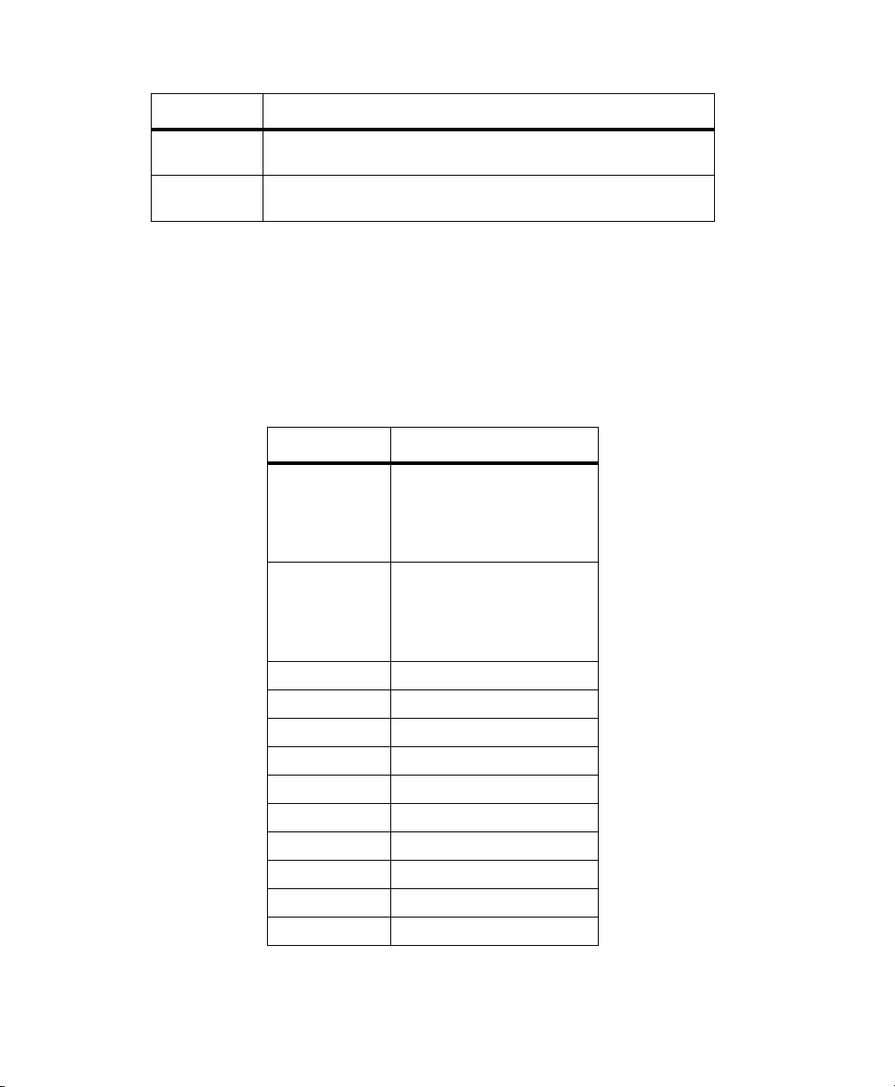
Table 1.4. $PASHR,RIO Message Format (Continued)
Field Description
f5 Receiver serial number (maximum 20 characters). Underscores
cc Checksum. XOR (exclusive or) of all characters between, but not
represent blank fields
including, the dollar sign ($) and asterisk (*) characters
Fourteen options are available. Each option is represented by a letter or number
presented in a certain order. The presence of given option is indicated by the
associated letter or number. If the letter or number is displayed, the option is
installed. An dash (“-”) indicates that the option is available, but not installed. An
underscore (“_”) indicates a reserved option slot.
Table 1.5 lists the options in the order in which they appear in the RIO response:
Table 1.5. G12 Option Descriptions
Option Description
[W = 20 Hz]
[T = 10 Hz]
[5 = 5 Hz]
[2 = 2 Hz]
[1 = 1 Hz]
[W = 20 Hz]
[T = 10 Hz]
[5 = 5 Hz]
[2 = 2 Hz]
[1 = 1 Hz]
[O] Raw Data Output
[P] Carrier Phase Tracking
[U] Differential - Remote Station
[B] Differential - Base Station
[I] RAIM Availability
[L] Timing Pulse Output (1PPS)
[E] Photogrammetry Event Marker
[G] Geoid Model
[M] Magnetic Variation Model
[-] Reserved
Position update rate
Raw measurement update rate
12 G12 OEM Board & Sensor Reference Manual
Page 27
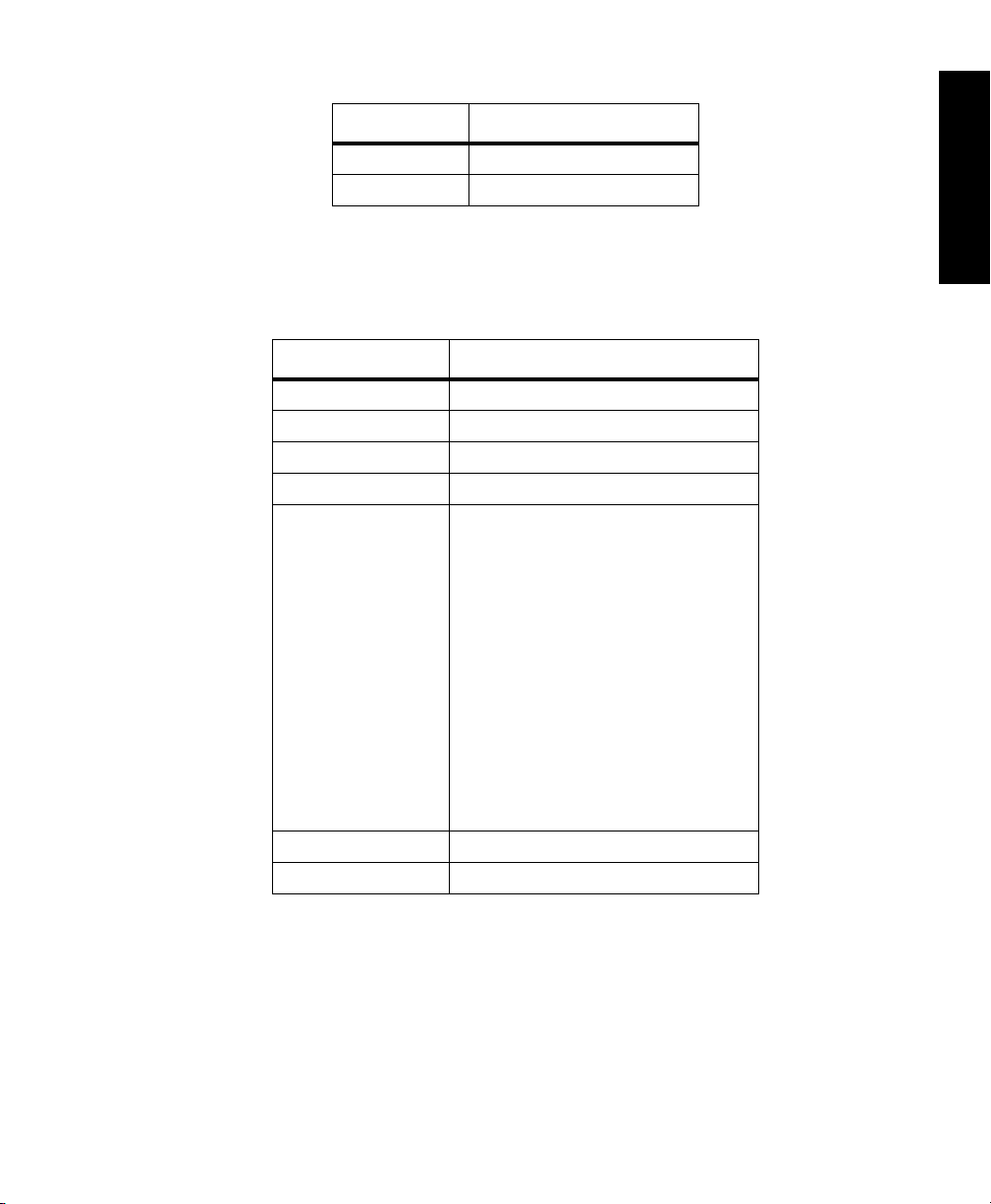
Table 1.5. G12 Option Descriptions (Continued)
Option Description
[C] Code Correlator
[-] Reserved
Typical RIO message:
$PASHR,RIO,G12,GM00,,1TOPUB_LEGM-C-, 710029150420*4D:
Table 1.6. Typical RIO Response
Field Description
$PASHR,RIO Message header
G12 Receiver type: G12
GM00 Receiver firmware version
[empty field] Channel firmware not available
1TOPUB_LEGM-C- Options available:
710029150420 Receiver serial number
*4D Checksum in hexadecimal
[1] 1 Hz position update rate
[T] 10 Hz raw measurement update
rate
[O] Raw data output
[P] Carrier phase
[U] Differential remote station
[B] Differential base station
[_] Option not installed
[L] 1 Pulse Per Second
[E] Photogrammetry
[G] Geoidal height
[M] Magnetic Variation
[-] Option not available
[C] Code Correlator
[-] Option not available
General Information
General Information 13
Page 28
See Chapter 4, Command/Response Formats, for more information on the G12 commands.
WARNING!
Take the following precautions to avoid damaging your G12 OEM Board:
1. Turn off power before connecting or disconnecting I/O-power cable and J301.
2. Ensure that when connecting the I/O-power cable to connector J301, pin 1 is correctly oriented per Figure 1.1.
3. Connect pin 15 (BATT_IN) to ground if it is not being used. Leave pin 17
(MAN_RES) open if it is not being used.
4. Isolate the center pin on the antenna connector from DC ground. The DC block
used between the center pin and DC ground should have the following characteristics:
• 1.15 maximum VSWR @ 1575 Mhz
• 0.2 db maximum insertion loss
• 5 VDC maximum applied voltage
5. Connect the RAM back-up battery to the appropriate pins on J301 and set the
SAV parameter to Y.
A lower-cost version of the G12, called G12-L, is also available. The G12-L
supports lower maximum update rates for position (5 Hz) and raw data (2 Hz),
and uses Ashtech’s edge correlator for multipath mitigation instead of the strobe
correlation technology in the standard G12. If higher update rates are required, or
if a high-multipath environment requires better multipath mitigation, the G12-L
can be upgraded with any of the features available for the standard G12.
There are two G12 evaluation kits available for purchase:
• G12 Sensor Evaluation Kit
• G12 OEM Board Evaluation Kit.
Figure 1.4, Figure 1.5, and Figure 1.6 on the pages that follow illustrate the
contents of the two evaluation kits.
The G12 Sensor Evaluation Kit contains a G12 receiver housed in an extruded
aluminum enclosure, an antenna, hardware accessories for power and
interfacing, and software to allow you to communicate with the receiver and
monitor its performance.
14 G12 OEM Board & Sensor Reference Manual
Page 29
The G12 OEM board Evaluation Kit includes the same antenna and accessories,
but contains a G12 receiver board and an interface board without the aluminum
housing.
An important difference between the G12 OEM board and the G12 Sensor is the
presence of a back-up battery for internal memory. The G12 Sensor has a backup battery installed. You must obtain and install a back-up battery for the G12
OEM board.
The power and interface cable supplied with the Sensor Evaluation Kit is used
with other Magellan products. Although it has three serial connectors, only ports A
and B are used with the G12.
G12 firmware is stored in flash memory. New firmware may be loaded into the
receiver through either serial port using a PC. Maintenance releases of firmware
are available on a regular basis to fix known bugs and to implement new features.
When embedding the G12 within another system, Magellan recommends that
external access to one of the receiver’s serial ports be designed into the system
for direct monitoring. For example, many system integrators use an internal data
cable to connect one of the G12 serial ports to an external DB9 connector.
General Information
General Information 15
Page 30
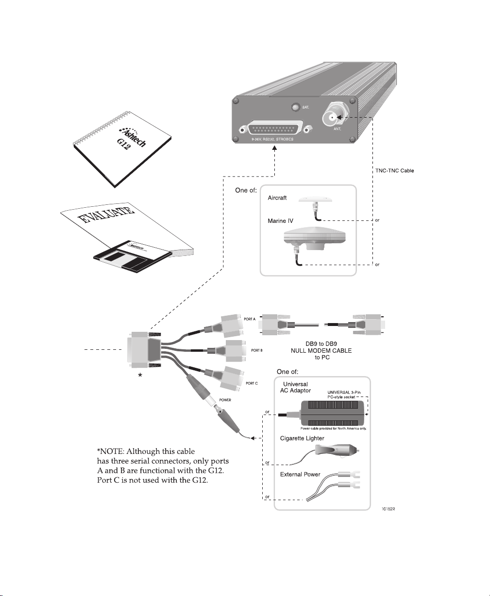
Figure 1.4. G12 Sensor Evaluation Kit
16 G12 OEM Board & Sensor Reference Manual
Page 31
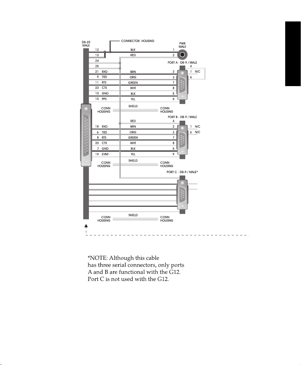
General Information
Figure 1.5. G12 Sensor Power-I/O Connections
General Information 17
Page 32
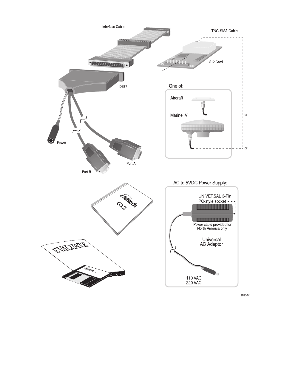
Figure 1.6. G12 OEM Board Evaluation Kit
18 G12 OEM Board & Sensor Reference Manual
Page 33

This section is intended to get you started using the G12 receiver. Please refer to
the chapters on General Information, Operation, and Command/Response
Formats for specific details regarding performance, power requirements, and
commands.
This chapter discusses the following topics:
• Connecting the G12 to power, connecting the antenna, and equipment
used for receiver control and data logging.
• Default parameters.
• Communicating with the G12 using standard communications software
and an IBM-compatible PC.
• Sending common commands to the G12.
Getting Started 19
Page 34
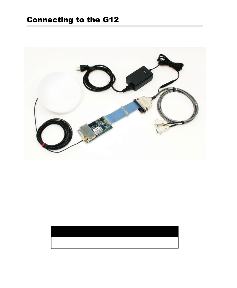
Figure 2.1 shows how to connect the components in the G12 Board system.
Universal Power
Supply
Antenna
Power I/O
Cable
Interface
Cable
Antenna
Cable
G12 Board
Figure 2.1. G12 Board Connections
Power
Before applying power, connect any controller devices or data logging equipment
to the input/output ports of the G12 by way of connector J301. Applying power to
the power input pins on connector J301 starts G12 operation.
Removing power from the power input pins on connector J301 stops G12
operation.
CAUTION
To avoid damage to the G12, always turn off the power supply before
connecting or disconnecting connector J301.
20 G12 OEM Board & Sensor Reference Manual
Page 35
1. Connect the female plug on the power cable to the J301 male connector on
the G12 before applying power.
2. Connect the power cable to the power supply.
Applying power to the G12 starts the unit. Once power is connected, the two-
color LED on the G12 GPS board flashes red.
Antenna
The G12 is designed to work with an antenna Low Noise Amplifier (LNA) that
requires five volts and is isolated from DC ground. The gain of the antenna LNA
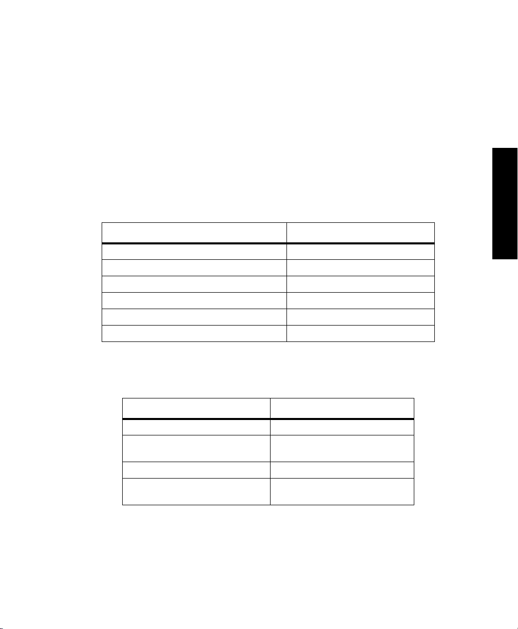
minus the loss of the cable is between 20 and 30 dB. Table 1 defines the antenna
requirements.
Table 2.1. Antenna Requirements
Requirement Parameter
GPS operational band 1575 ±10 MHz
Polarization type Right hand circular
Axial ratio Less than 3 dB in zenith of up area
Antenna gain for elevation angle of 10° No less than -2.5 dB
Antenna gain for elevation angle greater than 15° -1 to -2 dB
Antenna gain for elevation angle of 90° ~ +4 dB
Getting Started
Table 2 defines the antenna LNA requirements
Table 2.2. Antenna LNA Requirements
Requirement Parameter
Impedance of antenna output 50W VSWR <1.8
LNA gain Antenna/LNA gain minus cable loss:
Noise figure < 4.0 dB
LNA selectivity -3 dB bandwidth: 35 MHz
Getting Started 21
between 20 and 30 dB
-20 dB bandwidth: 60-70 MHz
Page 36
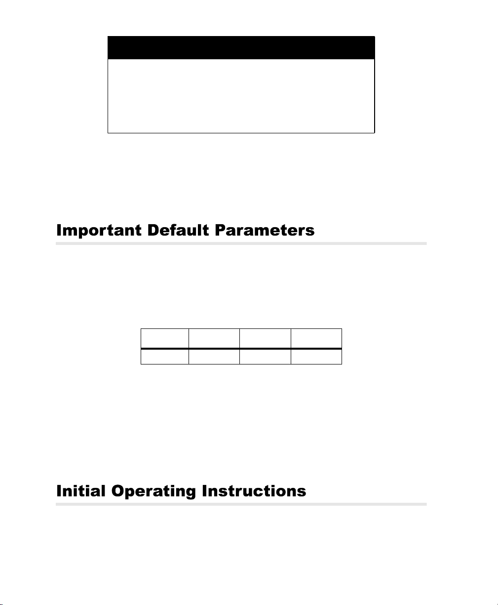
CAUTION
The G12 may be damaged if the center pin of the RF connector (Type
SMA) is not isolated from DC ground. Provide a DC block between
the center pin and ground; the DC block should have the following
characteristics:
• VSWR 1.15 maximum at 1575 MHz
• Insertion loss 0.2 dB maximum
• Maximum voltage 5 VDC
Connect the antenna cable directly to the antenna SMA connector on the G12.
Once power is on and the antenna is connected, the G12 acquires satellites (SVs
or Space Vehicles) within the field of view of the antenna. As a channel in the
G12 locks on to a satellite, the two-color LED flashes green between the red
power flashes for every channel in use (i.e., locked satellites).
Communication Port Setup
Table 3 lists the default communication parameters of the G12:
Table 2.3. G12 Communication Parameters
Baud Data Bits Parity Stop Bits
9600 8 None One
When first establishing communications with the G12, the communications
interface must use this protocol.
Data Output Options
All the default data output commands are set to OFF. The G12 does not output
any data until you command it to do so.
After the G12 is powered and running, you must send it command messages in
order to receive data (such as antenna position). The following procedure
22 G12 OEM Board & Sensor Reference Manual
Page 37

describes how to send commands to and receive information from the G12 using
an IBM-compatible PC. You can interface with the G12 using Evaluate
Software™, RCS (Receiver Communication Software™), or standard
communication programs such a ProComm or Hyperterminal. To begin, simply
connect the standard 9-pin serial cable supplied in the G12 evaluation kits
between port A on the G12 and COM1 on the computer.
After setting up the interface for establishing communications with the G12, you
are now ready to send commands. The letters in your command can be typed in
UPPER or LOWER case and completed by pressing <Enter>. If you sent the
command correctly, you should get a response.
The commands used with the G12 are divided into two groups: Set commands
allow you to change the G12’s operating parameters and begin with the command
string $PASHS. Query commands allow you request information from the G12,
such as the current operating parameters, current position, or DGPS status. Query
commands begin with the command string $PASHQ. The G12 responds to query
and set commands by issuing an acknowledgement of a change in operating
parameters or with the specific information requested through a query.
To become familiar with the G12 messages, send a few common commands to
the G12 and observe the responses. In the following steps, command messages
appear as COMMAND, and response messages appear as RESPONSE.
1. Type: $PASHQ,PRT and press <Enter>. This command queries the
communication setup of the port. If interfacing through serial port A, the
response message is:
$PASHR,PRT,A,5
This message indicates Port A of the G12 is using its default communications
setup 5: 9600 baud, eight data bits, no parity, and one stop bit.
2. Type $PASHQ,STA and press <Enter>. This command queries which
satellites are locked and their signal strength at the time the command is
sent.The response message typically might display:
TIME: 18:38:31 UTC
LOCKED:03 23 16
COUNT :54 26 17
3. If interfacing through port A, type $PASHS,NME,POS,A,ON,1 and press
<Enter>. This commands the G12 to return comprehensive position
information through port A at a set rate. The default rate for NME commands
is once per second. The response message output rate is 1 HZ:
$PASHR,POS,0,08,164152.90,3721.06962,N,12156.12176,W,+00003.16,
,008.64,000.55,+000.03,01.7,01.0,01.4,00.9,GH00*20
The data string contains the position information, assuming the receiver is
tracking a sufficient number of SVs to compute a position.
Getting Started
Getting Started 23
Page 38

4. If interfacing through port A, type $PASHS,NME,SAT,A,ON,1 and press
<Enter>. This command tells the G12 to return locked satellite information
through port A at a set rate. The response message output rate is 1 Hz
(default):
$PASHR,SAT,03,03,103,56,60,U,23,225,61,39,U,16,045,02,21,U*6E
The data string contains the number of SVs locked plus the elevation,
azimuth, and signal strength for each locked SV, and also indicates whether
a given satellite is used (U) or not used (-). Chapter 4 contains details on
these commands and responses, as well as the rest of the commands and
responses supported by the G12.
24 G12 OEM Board & Sensor Reference Manual
Page 39
This section covers a variety of G12 operating parameters and options, including
system setup, power-up, command format, serial port configuration, receiver
settings and status, the satellite search algorithm, position modes, altitude hold
definition, the ionospheric model, NMEA outputs, raw data outputs, differential
operation, the photogrammetry option, the pulse-per-second option, and other
options.
If you use equipment other than Magellan-supplied with the G12, it must comply
with hardware specifications as described in the “Hardware Description” section
on page 3.
Before applying power, connect any controller devices or data logging equipment
to the input/output pins on the J301 connector. Applying power to the power input
pins on the J301 connector starts G12 operation. Cutting the flow of power to the
power input pins on connector J301 stops G12 operation.
CAUTION
To avoid damaging the G12, always connect or disconnect the power
wiring to 30-pin connector J301 before turning on the power supply.
Power-Up
Upon power-up, the status LED (D302 on the G12 OEM board) lights red and
green and then continues to flash red, indicating the unit is on, but position has not
yet been computed. When the G12 locks on to a satellite, the status LED flashes
Operation 25
Page 40

green to indicate satellite lock and then red to indicate power status. Each
additional satellite to which the receiver locks on produces an additional green
flash; that is, if the receiver is locked onto seven satellites, the LED flashes green
seven times and red once. A short green flash (.25 sec) indicates the satellite is
locked but not used in position computations; a long green flash (.75 sec)
indicates that ephemeris for that satellite is available. Once the unit is locked to
enough satellites to compute a position (three or more), the duration of the red
flash becomes longer to indicate that positions are being computed.
The G12’s two RS-232 ports (A and B) can receive command messages from an
external control device, send response messages to an external control device
(such as a PC), output data to a separate data logging device, and send or
receive differential corrections from a reference or remote station.
G12 Input Messages
Input messages are comprised of set command messages, query command
messages, and general command messages. These messages comply with the
format defined in the NMEA 0183 standard to the following extent:
• NMEA 0183 ASCII byte strings following a dollar sign ($) character
• Data fields are separated by commas
• Checksum character delimiter and NMEA checksum bytes are recognized
by the G12 but are optional. The hexadecimal checksum is computed by
exclusive OR-ing all of the bytes in the message between, but not
including, the dollar sign ($) and the asterisk (*).
• Messages end with the standard NMEA message terminator characters,
[CRLF] (carriage return/line feed).
Input messages deviate from the NMEA standard as follows:
• Headers are Ashtech proprietary
• Message IDs are Ashtech proprietary
• Message length may exceed 80 characters
All command messages—set or query—can be composed in uppercase or
lowercase characters. All command messages are sent by pressing <Enter>. A
valid set command causes the G12 to return the $PASHR,ACK*3D
(acknowledge) response message. A set command containing a valid $PASHS
header followed by character combinations unrecognized by the G12 causes the
receiver to respond with $PASHR,NAK*30, a “not acknowledge” response
message indicating that the command is invalid. Valid query and messages are
acknowledged by return of the requested information. All invalid query and
26 G12 OEM Board & Sensor Reference Manual
Page 41
general commands cause the G12 to return the $PASHR,NAK*30 “not
acknowledged” response message.
G12 Message Output
The G12 can be programmed to send data to another device. Output messages
include general receiver status messages, ACK/NAK messages, and GPS data
messages. The general receiver status messages have free-form Ashtech
proprietary formats. The acknowledged/not acknowledged messages and GPS
data messages comply with NMEA 0183 standards as follows:
• NMEA ASCII byte strings following a dollar sign ($) character
• Headers are standard NMEA or Ashtech proprietary NMEA
• Message IDs are standard NMEA or Ashtech proprietary NMEA
• Standard NMEA format messages contain hexadecimal checksum bytes
• Data items are separated by commas; successive commas indicate invalid
or missing data (null fields)
• Messages end with [CRLF] (carriage return/line feed), the standard NMEA
message terminator characters
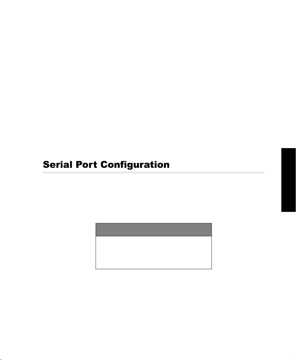
The G12 receiver has two RS-232 serial ports that support two-way, full-duplex
communication. The default protocol for transmitting or receiving data is 9600
baud, eight data bits, no parity, and one stop bit (8N1). The baud rate of the G12
ports is adjustable using the $PASHS,SPD speed set command; the data bit, stop
bit and parity protocol is always 8N1.
Operation
DEFAULT SETTINGS
The default parameters for the G12 serial ports:
•Baud Rate— 9600
•Data Bits— 8
•Stop Bits— 1
•Parity— None
On initial power-up, or after issuing the $PASHS,INI (receiver initialization)
command or the $PASHS,RST (restore defaults) command, the default data rate
is 9600 baud for both G12 serial ports.
The baud rates must be the same between the G12 serial port and the serial port
on the device with which it is interfaced.
Operation 27
Page 42
To maintain communication with the G12 while changing the baud rate, issue the
$PASHS,SPD (set port speed) to change the baud rate of the G12 port, then
change the baud rate of the command device to match the new baud rate setting
on the G12 port.
When the G12 is powered on for the first time, or when the power and back-up
battery have been disconnected, there is no almanac or ephemeris data in
memory. In these cases, the G12 assigns the first 12 elements of a 32-element
table of SV PRN numbers to its 12 channels as it begins searching for satellites. If
no ephemeris data are in memory, or if the data are older than ten hours, 30 to 60
seconds are needed to collect data. The G12 synchronizes its clock to GPS time
within six seconds of locking an satellite. After three or four satellites are locked
and the almanac and ephemeris data are collected, the G12 computes its first
position. The G12 continuously updates almanac, ephemeris, and position data in
its battery-backed memory to help optimize satellite reacquisition and time to first
fix when the unit is next powered on.
At the next power-up, if the almanac and ephemeris data are available in batterybacked memory, and if the ephemeris data are less than ten hours old, the G12
restricts its satellite search to those satellites that should be visible based on this
information. Under these conditions, the G12 on average recomputes position in
10 to 15 seconds (hot start). If the almanac and ephemeris data are available in
battery-backed memory, but the ephemeris data are more than ten hours old, the
G12 needs 30 to 40 seconds on average to compute a position (warm start). If
almanac and ephemeris data and a valid position are not available at power-up,
the G12 computes position in less than one minute on average (cold start).
On initial power-up or after issuing the $PASHS,RST (restore defaults) command,
the G12 reverts to its default parameter settings. Enter the following three
commands to query the G12 for the current parameter status:
1. $PASHQ,PAR (general parameters)
28 G12 OEM Board & Sensor Reference Manual
Page 43

The response message for the query command $PASHQ,PAR (general
parameters) is shown below:
SPDA:5 SPDB:5
GPS:YYYYYYYYYYYYYYYYYYYYYYYYYYYYYYYY
PMD:1 FIX:0 ALT:+00000.00 PDP:40 HDP:04 VDP:04
PEM:05 UNH:N ION:N SAV:N DTM:W84
RTC: OFF PRT:A
NMEA: LTN AIM POS GLL GXP GGA VTG GSN MSG GSA SAT GRS RRE TTT ZDA TCM
PRTA: OFF OFF OFF OFF OFF OFF OFF OFF OFF OFF OFF OFF OFF OFF OFF OFF
PRTB: OFF OFF OFF OFF OFF OFF OFF OFF OFF OFF OFF OFF OFF OFF OFF OFF
PER:001.0
2. $PASHQ,RAW (raw data parameters)
The command $PASHQ,RAW is functional only if the Binary Data Outputs
option (Option O) is installed in the receiver. An example of the response
message for the default values of $PASHQ,RAW (raw data parameters) is
shown below:
RCI:020.00 MSV:3 ELM:05 SIT:????
RAW: MBN PBN SNV SAL MCA
PRTA: OFF OFF OFF OFF OFF
PRTB: OFF OFF OFF OFF OFF
3. $PASHQ,RTC (differential parameters)
The $PASHQ,RTC query is available only if one of the differential options (B
or U) is installed in the receiver. The response message for the $PASHQ,RTC
(differential parameters and status) query command is shown below:
STATUS:
SYNC: TYPE:00 STID:0000 STHE:0
AGE:+000 QA:100.00% OFFSET:00
SETUP:
MODE:OFF PORT: A AUT:N
SPD:0300 STI:0000 STH:0
MAX:0060 QAF:100 SEQ:N
TYP:1 2 3 6 9 16
FRQ:99 00 00 OFF 00 00
BASE: LAT:0000.00000,N LON:00000.00000,E ALT:+00000.00
MSG:
Operation
Operation 29
Page 44

Saving Parameter Settings
New parameter settings can be saved by issuing the set command,
$PASHS,SAV,Y. You can verify that new settings are in effect by issuing query
commands to prompt the G12 for its current status. After the next power-up, the
query response messages display the new settings instead of the default
parameters. Issue the command $PASHS,RST to restore the default settings. If
the SAV command is not entered, the new settings will be lost, and the default
settings restored at the next power cycle.
Watchdog Timer
The G12 has a watchdog timer. If the processor hangs up for any reason, the
watchdog timer resets the receiver. On reset, the receiver uses the parameters
most recently saved during startup. If parameter settings were not saved, the
receiver uses the default settings at startup.
CAUTION
User-entered parameters are lost and default settings are restored if the
command $PASHS,SAV,Y is not entered before the next power cycle.
Position Modes
The G12 can perform position computations in four modes. The $PASHS,PMD
command allows you to set the position mode (page 82).
• Position Mode 0
At least four satellites at elevations equal to or above the position
elevation mask are needed to compute a position. The receiver stops
computing positions if the number of satellites tracked falls below three. All
three polar coordinates (latitude, longitude, altitude) are computed in this
mode.
• Position Mode 1
At least three satellites with elevation equal to or above the position
elevation mask are needed to compute a position. Only the latitude and
the longitude are computed if three satellites are locked and the altitude is
held fixed. For more information on fixed altitude modes, see”Fixed
Altitude Modes” on page 31. The receiver stops computing positions if the
number of satellites tracked falls below three. All three polar coordinates
are computed if more than three satellites are locked.
30 G12 OEM Board & Sensor Reference Manual
Page 45
• Position Mode 2
At least three satellites with elevation equal to or above the position
elevation mask are needed to compute a position. Only the latitude and
the longitude are computed and altitude is always held fixed even if the
receiver is tracking more than three satellites. The receiver stops
computing positions if the number of satellites tracked falls below three.
• Position Mode 3
At least three satellites with elevation equal to or above the position
elevation mask are needed to compute a position. Only the latitude and
longitude are computed, and the altitude is held if only three satellites are
locked. If more than three satellites are used and the HDOP is less than
the specified HDOP mask, all three polar components are computed. If
HDOP is higher than the specified HDOP mask, the G12 automatically
goes into the altitude hold mode. The receiver stops computing positions if
the number of satellites tracked falls below three.
DEFAULT SETTINGS
$PASHS,PMD— Position Mode 1
• Point Positioning Mode
The Point Positioning option improves the accuracy of a stand-alone
absolute position of a stationary receiver from about 50 meters to less than
five meters over a period of four hours, and can typically get down to a
couple meters level after ten hours. Point positioning uses an averaging
technique to reduce the effects of Selective Availability (SA) and other
fluctuating errors. Point positioning mode can be set using the
$PASHS,PPO command. Refer to Chapter 3 for details of this command.
The Point Positioning receiver option [T] must be set in the receiver for this
command to work.
Operation
Fixed Altitude Modes
Two modes define the altitude setting when the G12 is in altitude hold mode. The
$PASHS,FIX set command (page 67) can be used to select between modes .
• Fixed Altitude Mode 0
The most recent altitude is used. This is either the altitude entered by
using the $PASHS,ALT set command or the one computed when four or
Operation 31
Page 46

more satellites are used in the position solution and the VDOP value is
below the VDOP mask, whichever is most recent.
• Fixed Altitude Mode 1
Only the last altitude entered through the command $PASHS,ALT is used
in the position fix solution.
On initial power-up, or after issuing the $PASHS,INI command (initialize memory)
or $PASHS,RST command (restore defaults), the antenna altitude is set to zero.
DEFAULT SETTINGS
$PASHS,FIX— Fixed Altitude Mode (0)
Geoid Model
The G12 uses the Ohio State University 91A geoid model (OSU91A). For more
information on OSU91A, refer to the Ohio State University:
Rapp, R.H., Y.M. Wang and N.K. Pavlis, 1991: The Ohio State 1991
Geopotential and Sea Surface Topography Harmonic Coefficient Models,
Report No. 410. Columbus: Department of Geodetic Science and
Surveying, The Ohio State University.
The Ohio State University
Department of Civil and Environmental Engineering and Geodetic Science
470 Hitchcock Hall
2070 Neil Avenue
Columbus, OH 43210 USA
Tel: 614-292-2771
Fax: 614-292-3780
Web: http://www-ceg.eng.ohio-state.edu
Ionospheric Model
The G12 can use ionospheric and tropospheric models in its position
computations to compensate for errors caused by ionospheric and tropospheric
delay. This mode of operation is typically used to improve autonomous accuracy
by minimizing the influence of the ionosphere and troposphere on the code phase
of the GPS signal. When the G12 is in differential mode (base or rover),
ionospheric and tropospheric modeling is disabled because differential GPS
already compensates for delays associated with the ionosphere and troposphere.
When the receiver is in autonomous mode, ionospheric and tropospheric
modeling is enabled.
32 G12 OEM Board & Sensor Reference Manual
Page 47

The ionospheric model used by the G12 is based on the model defined in ICDGPS-200, Revision B. The tropospheric model is based on the Bean and Dutton
model. For more information on ICD-GPS-200, refer to ARINC Research
Corporation:
ARINC Research Corporation
2250 E. Imperial Highway, Suite 450
El Segundo, CA 90245-3509 USA
Tel: 310-524-1557
Web: http://www.arinc.com/products_services/gpshome.html
Magnetic Variation Model
The G12 uses the Joint US/UK 1995 Epoch World Magnetic Model (WMM-95).
For more information on WMM-95, refer to the USGS National Geomagnetic
Information Center:
USGS National Geomagnetic Information Center
Box 25046, Mailstop 968
Denver Federal Center
Denver, CO 80225-0046 USA
Tel: 303-273-8475
Fax: 303-273-8450
Web: http://geomag.usgs.gov
Operation
Setting Antenna Position
When in Differential Base Mode, the G12 uses an accurate antenna position
(reference position) entered by the user to calculate range corrections by
subtracting the measured range from the true range. Two commands can be used
to enter the reference position:
$PASHS,POS (position setting including latitude, longitude, altitude).
$PASHS,ALT (antenna height setting).
NMEA Outputs
The G12 can output a variety of NMEA messages and Ashtech’s NMEA-style
messages. Standard NMEA messages are output as a string of ASCII characters
delimited by commas, in compliance with NMEA 0183 Standards (version 2.2).
Ashtech’s NMEA-style messages are also output in a comma-delimited string of
ASCII characters, but may deviate slightly from NMEA standards. For example,
the maximum length of a standard NMEA message is eighty characters, but the
length of some Magellan messages goes beyond eighty characters.
Operation 33
Page 48

Both NMEA messages and Magellan’s NMEA-style messages begin with a dollar
sign ($) and end with a Carriage Return/Line Feed <CR><LF> delimiter.
Any combination of these messages can be output through either serial port at the
same time, and you can even choose to send the same message can be output
through both ports. The output rate is determined by the $PASHS,NME,PER
command, and can be set to any value between 0.05 and 999 seconds depending
upon the update rate option installed (20, 10, 5, 2 or 1 Hz). For more information
refer to the “NMEA Commands” section on page 139.
The output rate can be set to any value between 0.05 and 999 seconds. The
default setting for the output interval is one second. See Chapter 4, Command/
Response Formats, for more information on NMEA messages and Ashtech’s
NMEA-style messages.
DEFAULT SETTINGS
Output interval setting for NMEA messages and Ashtech NMEA-style
messages is one second.
Raw Data Output (Optional)
The G12 has an optional feature that allows you to output raw data (also called
real-time data) through serial ports A and B. Five different messages can be
output:
• MBN: Contains measurement data for each locked satellite using the
Ashtech type 2 data structure.
• PBN: Contains position and velocity data.
• SNV: Contains satellite ephemeris data.
• SAL: Contains satellite almanac data in a proprietary format.
• MCA: Contains measurement data (same as MBN) for each locked
satellite using the Ashtech type 3 data structure
All raw data messages are in binary format. The transmission protocol remains
the same: 8 data bits, 1 stop bit, and no parity bit. Any combination of messages
can be output through any of the serial ports, and the same messages can be
output through different ports at the same time. The output interval is determined
by the $PASHS,RCI command, and can be set to any rate between 0.05 and 999
seconds depending upon which option has been selected for the raw
measurement update rate (20, 10, 5, 2, or 1 Hz). For more information on the
34 G12 OEM Board & Sensor Reference Manual
Page 49
structure and content for all the above messages, refer to “Raw Data Commands”
section on page 113.
DEFAULT SETTINGS
Output interval setting for raw data messages is 20 seconds.
This section contains a general discussion of real-time differential operation,
including basic concepts, sources of error, G12 commands related to differential
GPS, plus format and content for the RTCM-SC104 (Sub-committee 104)
correction messages supported by the G12. Differential remote [U] and base [B]
operation are available as receiver options. Both options must be installed in order
for the G12 to be able to support both differential modes (base and rover).
When the G12 is set as a differential base or rover, the port which is designated to output or receive
differential corrections can no longer be used to communicate with the receiver. If you have set the
receiver to output RTCM corrections through port A, you can communicate with the receiver
through port B only. You must disable differential mode in order to resume communication with the
receiver through port A.
General
Operation
Real-time differential positioning involves a reference (base) station calculating
range corrections for each satellite it is tracking and transmitting them to the
remote (rover) stations through a real-time data communications link. Remote
receivers apply the corrections to their own range measurements and use the
corrected ranges to compute positions.
The base receiver determines range correction by subtracting the measured
range from the true range. A precise reference position must be entered in the
base receiver before true range can be calculated. The reference position must
have been previously surveyed using GPS or some other comparable technique.
RTCM type 1 corrections with a UDRE (User Differential Range Error) field set to 3 (one-sigma
differential error > 8 meters) are not used.
As a stand-alone receiver, the G12 can compute a position with ± 3 meter CEP
(Circular Error Probable) of accuracy (on average) with Selective Availability (SA)
off. Autonomous accuracy worsens to an average of ±100 meters with SA on. In
differential mode, a G12 in rover mode can achieve sub-meter accuracy.
Operation 35
Page 50
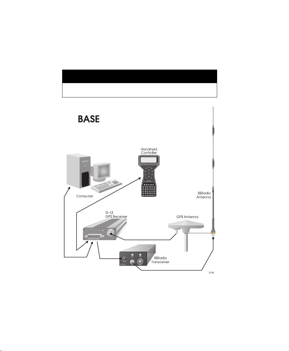
Real-time differential operation requires a communication link between the base
and rover receivers. A wireless link, such as a radio-modem link or cellular/
modem link is typically used, although any other medium that can transfer digital
data can be used.
Figure 3.1 and Figure 3.2 display a typical DGPS base station and remote system
configuration.
CAUTION
Errors in the base station reference position will be duplicated in
positions computed by the remote system.
Figure 3.1. RTCM Base Station System
36 G12 OEM Board & Sensor Reference Manual
Page 51
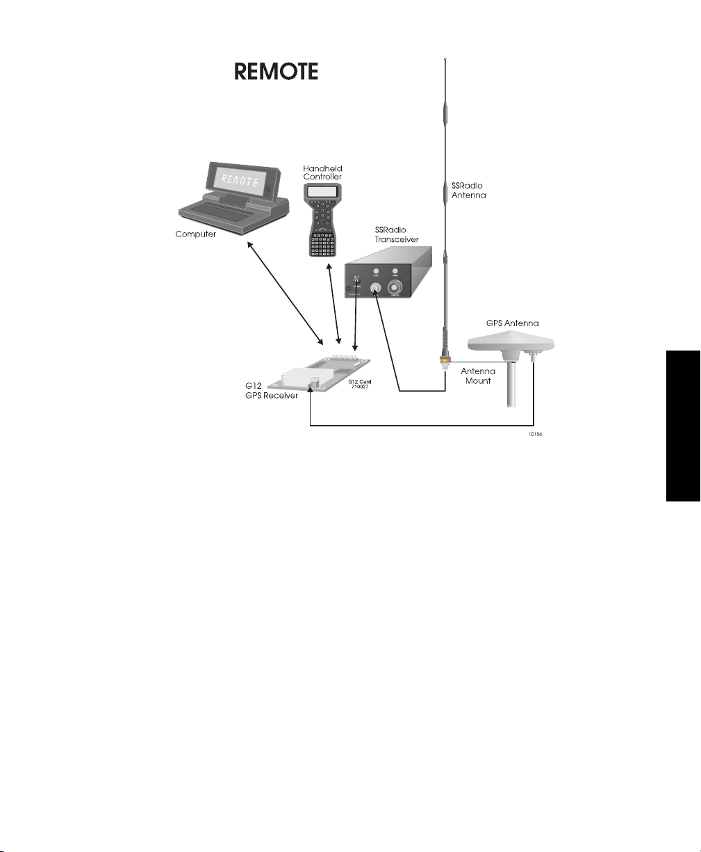
Figure 3.2. RTCM Remote System
Sources of Error
The major sources of error affecting the accuracy of GPS range measurements
are satellite orbit estimation, satellite clock estimation, ionosphere, troposphere,
multipath, and receiver noise in measuring range. The first four sources of error
are almost totally removed by differential corrections. The residual error is in the
order of one millimeter for every kilometer of separation between base and remote
receivers.
Receiver noise is not correlated between the base and the remote receiver and is
not canceled by differential GPS. However, in the G12, integrated doppler
measurements are used to smooth the range measurements and reduce the
errors resulting from receiver noise.
At the instant an satellite is locked, there is also RMS noise affecting the range
measurement. RMS noise is reduced over time by the square root of the number
of measurements computed by the receiver. For example, after 100 seconds of
locking to a satellite, the rms noise in range measurement is reduced by a factor
Operation
Operation 37
Page 52

of 10 (one meter of noise is reduced to 0.1 meter). The noise is further reduced
with each additional measurement.
If the lock to a satellite is lost, the noise goes back to one meter and smoothing
starts from the one-meter level. The loss of lock to a satellite is rare, and typically
happens only when the G12 antenna’s line of sight to the satellite is blocked by an
object, or when the satellite goes below the horizon.
Total position error (or error-in-position) is a function of the range errors (or errorsin-range) multiplied by the PDOP (three-coordinate position dilution of precision).
PDOP is a function of satellite geometry; that is, the positions of the satellites in
relation to one another.
RTCM Messages
The G12 accepts differential correction messages in the RTCM format (refer to
RTCM Recommended Standards for Differential GNSS, version 2.2). The G12
can be set to output or receive RTCM messages using either of its two ports by
issuing the set command $PASHS,RTC,s1,c2 where s1 is either BAS (base
station mode) or REM (remote mode) and c2 is the port designator for the input or
output of differential corrections. The G12 supports six out of the 64 different
types of RTCM messages. Message type 3 contains base station status
information. Message type 16 contains a special ASCII message of up to 90
characters. Type 16 messages are used to communicate special information. For
example, a base station operator may wish to construct a message informing
users that the base station will go offline temporarily in order to perform routine
maintenance or repairs. Message types 1, 2, and 9 contain data used for position
correction. The type 6 message is a null frame message which is used to
establish and maintain RTCM message frame synchronization for remote
differential stations. RTCM messages are processed automatically by the G12.
Although RTCM messages are output in binary format, it is possible to convert
them to ASCII format through the $PASHS,NME,MSG set command and the
$PASHQ,MSG query command.
All RTCM messages except type 1 are generated by the base station only if they
are enabled using the $PASHS,RTC,TYP set command. In addition, if type 1 or
type 9 messages are enabled and a change of ephemeris occurs in one or more
satellites, the base station automatically generates a type 2 message with the
delta IODE (Issue of Data, Ephemeris) information. The type 2 message is
generated regardless of whether the type 2 message has been enabled for
output. When a G12 set in differential remote mode receives a type 2 message,
and the IODE information in type 1 or 9 messages does not match, the remote
receiver uses the delta ephemeris information in the received type 2 message
until the IODE information in the incoming type 1 or 9 messages matches the
IODE information in the received type 2 message.
38 G12 OEM Board & Sensor Reference Manual
Page 53

On initial power-up, or after issuing the $PASHS,RST command (restore
defaults), the G12’s setting for differential mode is OFF, and the setting for the
maximum age of an RTCM differential correction is 60 seconds, meaning that an
incoming correction whose age is greater than 60 seconds is not used. If
automatic differential GPS mode is not enabled ($PASHS,DIF,AUT), and if the
differential correction data is unavailable or is older than the maximum age
specified by the $PASHS,RTC,MAX set command, a G12 set as a remote
differential station will not output position data. If automatic differential mode is
enabled, a G12 set as a remote differential station will output uncorrected
positions if differential correction data is unavailable or if the age of correction
exceeds the maximum age setting.
RTCM 104 Format, Version 2.2
When the RTCM base option is enabled and the G12 is configured as a reference
station, it computes differential corrections for up to 12 satellites, converts those
corrections to RTCM format and outputs the converted messages through its
serial ports. The G12 generates message types 1, 2, 3, 6, 9, and 16, listed in
Table 3.1:
Table 3.1. RTCM Format
Message
Typ e
1 Differential GPS corrections
2 Delta differential corrections
3 Reference station coordinates
6 Null frame
9 High-rate differential GPS corrections
16 Special Message
Contents of message
The G12 uses the six-of-eight format (data bits a1 through a6 of an eight-bit byte)
for differential corrections.
When the RTCM remote option [U] is installed and the G12 is set in differential
remote mode, it can decode RTCM message types 1, 2, 3, 6, 9, and 16, but uses
only types 1, 2, and 9 to correct its position calculations. When using radiomodems for the communication link, the G12 in remote mode is able to recover bit
slippage.
Operation
Operation 39
Page 54
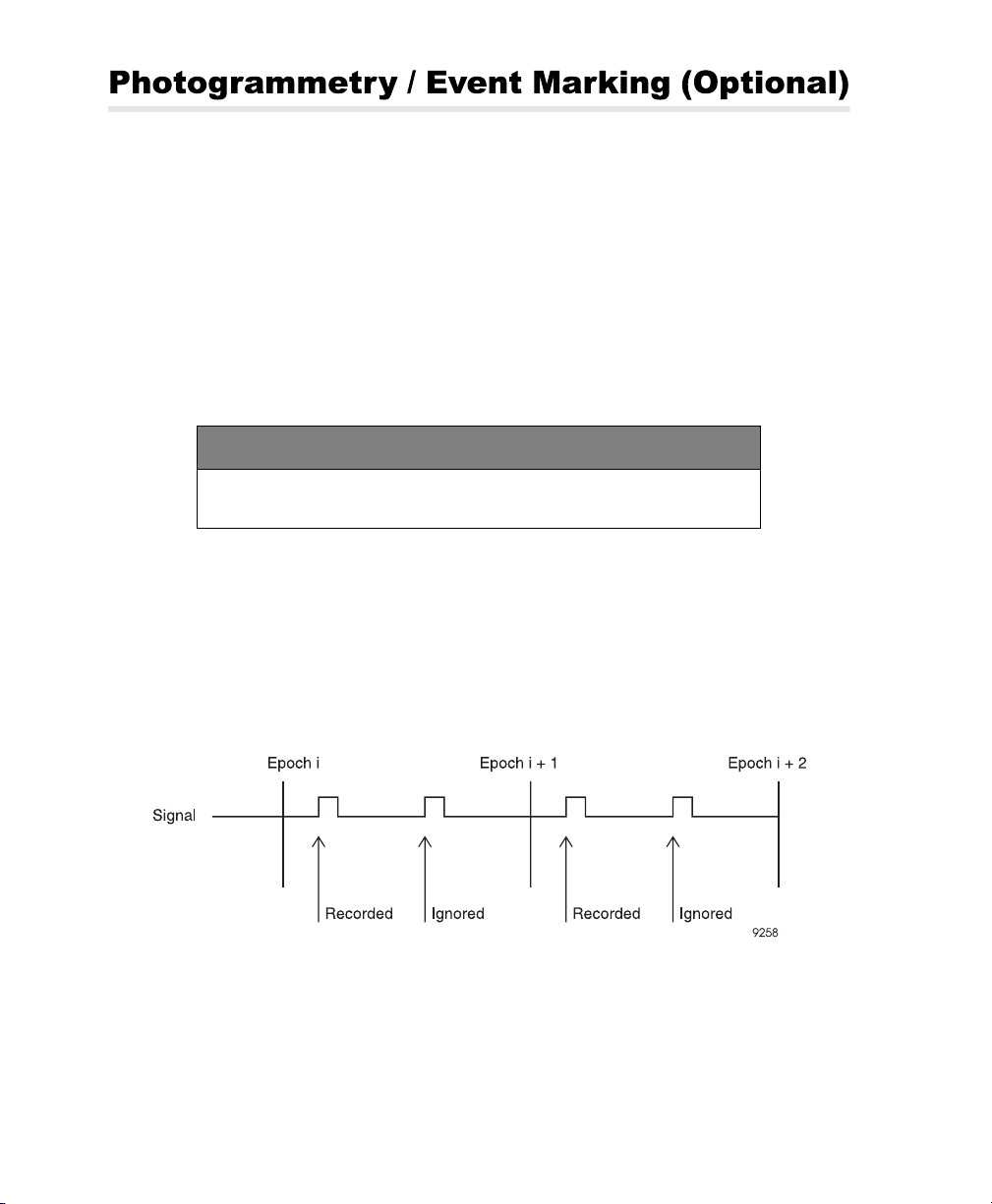
With the photogrammetry [E] option installed, the G12 can measure and record
events with high accuracy. This is an input signal that is received into a 10K ohm
impedance; the signal must be at TTL levels for proper functioning. In order to
measure an event time, a trigger signal must be sent to pin 27 on connector J301.
This input can be driven with either TTL or a switch that grounds the pin. The
photogrammetry feature allows the event time to be output by using the
$PASHS,NME,TTT command.
After enabling the TTT message, the time is measured at the rising or falling edge
(selectable) of the trigger signal, causing and the TTT NMEA message is output.
The trigger signal can be set to the rising or falling edge using the $PASHS,PHE
command.
DEFAULT SETTINGS
TTT synchronization message output— synchronize with the rising edge
of the trigger signal
The precision of the measured time is 135 nanoseconds (ns) in differential mode
and 280 ns in stand-alone mode with SA on. This is based on GPS time, which is
output as day number, hours, minutes, seconds, and fractional seconds to 6 digits
past the decimal mark.
The photogrammetry time measures the event time relative to the receiver's GPS
time. It measures only the first event during the period between 2 GPS epochs
(Figure 3.3).
Figure 3.3. GPS Epochs
40 G12 OEM Board & Sensor Reference Manual
Page 55

CAUTION
The G12 measures only one event time per data collection period. If more than
one event time is measured within a data collection period, the receiver measures
only the first one. The event time record rate is dependent upon the setting of the
RCI parameter.
Because the 1 PPS signal is used to measure the photogrammetry events, the
period of the 1 PPS signal must be set to a value equal to or less than the period
of the event pulse.
The trigger pulse may be TTL-compatible or open collector. Minimum pulse
duration is 100 nanoseconds when the signal is not terminated at the receiver
input. The impedance is approximately 5 KW.
Use a coaxial cable with BNC connectors to connect the camera trigger output to
the photogrammetry input connector of the G12.
Time Tagging the Shutter Signal
In this technique, the signal generated by the camera shutter is fed to a GPS
receiver for accurate time-tagging which can then be post-processed with the
GPS observations. Since the time of the picture is not synchronized with the time
that the GPS measurement is taken, the two position computations before and
after the shutter time are interpolated to compute the position of the camera at the
time the picture was taken.
If GPS measurements are recorded at the rate of one per second, the average
distance an aircraft travels in ½ second is about 100 meters. Therefore, the
distance between the position of the camera at the time the picture was taken and
the GPS position fixes can be as much as 50 meters. The motion of the aircraft
during this time may be in the meter range.
To minimize the errors discussed above, the closed loop technique is
recommended.
Operation
Operation 41
Page 56
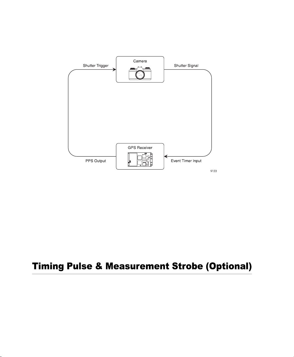
Closed-Loop Technique (Advanced Trigger)
The closed-loop technique combines PPS synchronization and shutter timing
(Figure 3.4).
Figure 3.4. PPS Synchronization
In this technique, the 1PPS output of the G12 triggers a camera shutter. The
camera shutter generates a signal that is fed to the G12 for accurate time tagging,
better than one microsecond.
The delay between the camera receiving the pulse and triggering the
photogrammetry port should be calculated. This may then be applied so as to
advance the 1PPS from the G12 so that the shutter time exactly matches the
GPS time for the epoch. No interpolation between the shutter time and the GPS
position time will be needed.
When the timing pulse option [L] is installed, the G12 can output a timing pulse
synchronized with GPS time to an accuracy of ±1 microsecond. The timing pulse
is a TTL-level square wave signal output on pin 18 of the J301 connector and is
fed into a 75-ohm impedance. The pulse is generated by default once every
second (1PPS, or 1 pulse-per-second) with no offset from GPS time and with the
rising edge of the pulse synchronized to GPS time. Using the $PASHS,PPS
42 G12 OEM Board & Sensor Reference Manual
Page 57

command, the period of the pulse can be changed from 0.10 of a second up to
99.90 seconds, depending upon the receiver update rate, which, in turn, is
dependent upon the installed position update rate and raw data update rate
options.The timing pulse may be offset from GPS time within a range of -999.9999
to +999.9999 milliseconds. GPS time can be synchronized to the rising or falling
edge of the square wave pulse.
DEFAULT SETTING
PPS Period 1 second
Offset 0.0000 milliseconds
Synchronization
GPS time synchronized to the rising edge of the
pulse
Figure 3.5 shows timing pulse characteristics under default conditions. The pulse
occurs when the signal goes high (i.e., goes from zero to five volts). The pulse is
generated within ±1 microsecond of the GPS second and remains high for 1-2
milliseconds. The precision of the epoch between pulses is ±190 nanoseconds in
stand-alone mode with SA active and ±45 nanoseconds when the G12 is
receiving differential corrections. The G12 must be computing positions and
tracking a minimum of four satellites in order for the one microsecond accuracy
and 45/190 nanosecond precision to be valid.
Operation
Figure 3.5. Timing Pulse Characteristics
In order to provide notification to peripheral equipment and software with respect
to time tagging the occurrence of the timing pulse, it is necessary to set the output
of PBN raw data message to match the period of the timing pulse. The GPS time
value contained in the PBN message plus one second is the time that the next
pulse will occur when the default settings are in effect (Figure 3.6). PBN time is
already internally rounded to GPS time, so it is the actual time to which the
navigation 1PPS pulse generation which preceded it (unless that pulse has been
Operation 43
Page 58
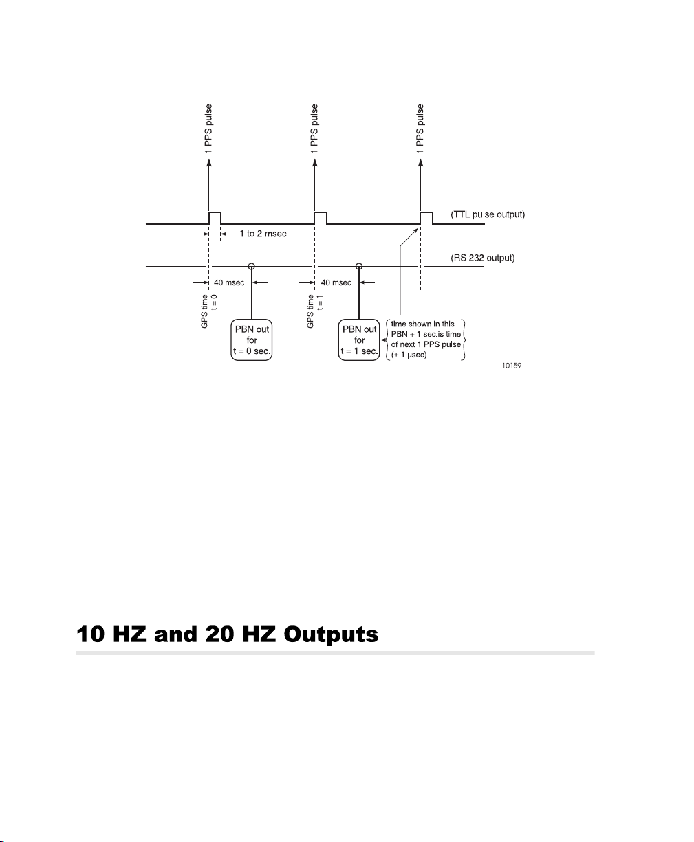
intentionally advanced or retarded). The latency of PBN message output is
normally about 40 milliseconds after the timing pulse event.
Figure 3.6. Relationship of GPS Time in PRN Record to 1PPS Pulse
The timing pulse option [L] includes a secondary measurement strobe output on
pin 23 of 30-pin connector J301. The measurement strobe is also a TTL-level
square-wave signal fed into a 75-ohm impedance, and is also synchronized with
GPS time to an accuracy of ±1 microsecond. Output of the measurement strobe is
controlled by the $PASHS,STB command and is synchronized with GPS time.
The period depends upon the xxxx value and the setting of the RCI parameter.
The ±yyy.yyyy field allows you to set an offset value from GPS time with a
resolution of 100 nanoseconds, and also allows you to synchronize the rising or
falling edge of the output with GPS time. The accuracy of the measurement
strobe output is 0.5 milliseconds. For more information, see Chapter 4,
Command/Response Formats.
The G12 provides the optional capabilities of 10 Hz or 20 Hz internal update rates
for position and raw data computations. When these options are installed, the
G12 can output NMEA messages and raw data messages at intervals of 0.1 or
0.05 seconds (see Table 1.4 for a list of the available options). Because of power
limitations in the G12’s CPU, when the receiver is set to update position and raw
44 G12 OEM Board & Sensor Reference Manual
Page 59
data at 20 Hz ($PASHS,POP,20), it uses no more than 10 satellites in the
navigation solution, although it continues tracking up to 12 satellites. During
periods in which a 20 Hz update rate is not required, you can revert to a 10 Hz
update rate and resume using up to 12 satellites in the position solution by issuing
the command $PASHS,POP,10.
CAUTION
When collecting data at 10 or 20 Hz, a 486-33 MHz or Pentium computer with a fast
serial and parallel port card (i.e., 16550 serial and parallel card) is required
because of large amounts of data being output through the serial ports. The serial
port baud rate should be set to 115200.
RAIM (Receiver Autonomous Integrity Monitoring) provides the detection of
anomalous satellite pseudorange error with miss detection probability 0.999 and
false alarm probability 0.002 per hour (requirements from RTCA/DO-208) under
given horizontal alarm limit in range 200 m to 2 nautical miles. In addition, RAIM
isolates wrong satellite and correct position and velocity errors.
RAIM includes three procedures which are called every epoch. The first one is
Availability Check which checks current satellites constellation available to
determine the possibility of anomalous error detection with given alarm threshold,
false alarm and miss detection probabilities. Availability percentage depends on
alarm threshold value, satellites number and their position. The less alarm
threshold is, the less availability percentage will be. For example, if 7 satellites
with good PDOP are in view and alarm threshold is the one nautical mile
(terminal mode), detection is always available. If only 4 satellites are visible,
detection is impossible.
If detection is available then Detection procedure is called. Detection algorithm
compares the residuals with threshold depending upon the number of redundant
satellites in view. If the threshold is exceeded then anomalous error is detected.
RAIM is a snapshot type algorithm, so detection usually takes place at the first
epoch after the alarm limit being exceeded.
If error is detected and at least 6 satellites with good PDOP are in view, then the
Exclusion And Correction algorithm is called. The Exclusion And Correction
algorithm determines the number of "wrong" satellites by maximal normalized
residual, after that the position and velocity are corrected by exclusion of that
"wrong” satellite. To avoid possible incorrect isolation, the rest of the satellites' set
is tested by Availability Check and Detection algorithm. If the rest of the satellites'
set is available and no error is detected, it means the successful correction of
Operation
Operation 45
Page 60

position and velocity. The procedures above can be executed recursively. It
provides the possibility of more than one simultaneously wrong satellite exclusion.
However, in some cases where not enough satellites are available or too many
errors are detected, the probability requirement can not be met because of
statistical limitations.
46 G12 OEM Board & Sensor Reference Manual
Page 61
This chapter covers the formats and content of the serial port commands through
which the G12 receiver is controlled and monitored. These serial port commands
set receiver parameters and request receiver status information and other data.
Use Evaluate™ software or any other standard serial communication software to
communicate with the receiver. Note that the baud rate and protocol of the computer
COM port must match the baud rate and protocol of the receiver port for commands
and responses to be successfully transmitted and received. The communication
protocol is 8 data bits, 1 stop bit, and no parity.
All messages sent by the user to the receiver are either “Set” command messages
or “Query” command messages. Set commands generally change receiver
parameters and initiate data output. Query commands generally request receiver
status information. All set commands begin with the string $PASHS; all query
commands begin with $PASHQ. $PASHS and $PASHQ are the message headers.
They are required for all set or query commands. All commands must end with an
<Enter> or <CR><LF> (Carriage Return/Line Feed) keystroke in order to send the
command to the receiver. If desired, an optional checksum may precede the
<Enter> characters. All response messages also end with <Enter> or <CR><LF>
characters. Please note that some messages are functional only if the appropriate
option is installed.
When a command is sent to one of its serial ports, the G12 responds by outputting
a message indicating the acceptance or rejection of the command. In the case of
query commands, the G12 either outputs a response message containing data
relevant to the query or sends a “NAK” response, indicating that the query command
was invalid. All G12 response messages begin with the string $PASHR, including
status messages that are set for output at regular intervals from either of the G12’s
serial ports.
47
Page 62

G12 serial port commands fall into four groups:
• Receiver commands
• Raw data commands
• NMEA message commands
• RTCM differential commands
The following sections discuss each type of command. Within each section, the
commands are listed alphabetically and described in detail. A description of the
command, the command structure, the range and default states of command
parameters, and an example of how a given command is used are presented for
each command. These parameters may be either characters or numbers
depending upon the command. Table 4.1 lists the symbols and the types of data
represented by them used to illustrate message structures in the ASCII format:
Table 4.1. Command Parameter Symbols
Symbol Parameter Type Example
c 1 character ASCII N
d Numeric integer 3
f Numeric real 2.45
h Hexadecimal digit FD2C
m Mixed parameter (integer and real) for lat/lon or time 3729.12345
s Character string
*hh Hexadecimal checksum; always preceded by an asterisk (*) *A5
48 G12 OEM Board & Sensor Reference Manual
Page 63

Receiver commands allow you to change or query the status of various operating
parameters such as elevation mask, antenna altitude, position mode, etc. In this
context, set commands are used to change the G12’s operating parameters. Query
commands prompt the G12 to output status messages for parameter settings and
receiver operation. If an invalid set or query command is issued, a “not
acknowledged” (NAK) response is output:
$PASHR,NAK*30
Set command messages can be accepted by either serial port. When the G12
receives a valid set command message, it returns an "acknowledged" (ACK)
message:
$PASHR,ACK*3D
The G12 returns a NAK message if the command is invalid. The set command
$PASHS,SAV,Y<Enter> instructs the G12 to save user-entered operation
parameters; the G12 returns $PASHR,ACK*3D to acknowledge that the command
was valid and the instruction was carried out. The set command
$PASHS,SAV<Enter> is incomplete, and would cause the G12 to flag it as an
invalid command by responding with a “not acknowledged” response:
$PASHR,NAK*30.
The set command message structure is as follows:
“Header,Command ID,<Command Parameters>*Checksum<Enter>”
The header field always contains $PASHS. The command identifier field contains
a three character string and is followed by the command parameters. The checksum
is strictly optional. All set commands are terminated with an <Enter> or <CR><LF>
keystroke. All command string elements between the dollar sign ($) and the asterisk
(*), including the command parameters, are comma delimited; that is, the header,
the ID string, and the individual command parameters are separated by commas.
Enter the following set command to set the HDOP mask value:
$PASHS,HDP,6<Enter>
Query commands are used to request current GPS information and receiver status
information such as baud rate settings, position information, and tracking
information. Query command messages can be sent to either of the G12’s serial
ports. Most query commands allow you to designate the port from which the
response message is sent. The G12 acknowledges a valid query command
message by sending the requested response message through the specified port.
If the port is not specified in the query command, the response is sent from the
same port which received the query. The requested information is sent once each
time the command is issued and is not repeated.
Commands
49
Page 64
The query command message format is as follows:
$PASHQ,xxx,<optional query parameter>*hh<Enter>
Table 4.2 contains descriptions of the query command elements.
Table 4.2. Query Command Structure
Field Description
$ NMEA message start character
PASHQ Proprietary Ashtech header for query messages.
xxx Message identifier.
<optional query parameter> Designates the data port from which the query response message is
* Checksum delimiter.
hh Hexadecimal checksum value (checksum is optional).
to be sent.
The query command $PASHQ,CRR instructs the G12 to output a response
message indicating the currently selected code correlation mode:
$PASHR,CRR,E,E,E,E,E,E,E,E,E,E,E,E*37
The query command $PASHQ,CR<Enter> is incomplete, and causes the G12 to
flag it as an invalid message by outputting the NAK response.
Table 4.3 contains a list of the set and query commands falling into the category of
receiver commands. The commands are listed alphabetically by function, and then
alphabetically within each function. The commands are described in detail in the
pages following Table 4.3.
Table 4.3. Receiver Commands
Command Description Page
ANTENNA POSITION
$PASHS,ALT Set ellipsoidal height of antenna 54
$PASHS,POS Set base station reference position 86
$PASHQ,POS Query current position 86
$PASHS,POS,CUR Set current position as base station reference position 86
DILUTION OF PRECISION (DOP)
$PASHS,HDP Set HDOP mask for position computation 71
$PASHS,PDP Set PDOP mask for position computation 81
$PASHS,VDP Set VDOP mask for position computation 111
50 G12 OEM Board & Sensor Reference Manual
Page 65
Table 4.3. Receiver Commands (Continued)
Command Description Page
IONOSPHERIC AND TROPOSPHERIC MODELLING
$PASHQ,ION Query ionospheric measurements 73
MEMORY
$PASHS,INI Clear internal and BBU memory 72
$PASHQ,MEM Query memory status 77
$PASHQ,RSO Query receiver serial number and options 95
$PASHS,RST Restore default parameter settings 95
$PASHS,SAV Save parameters to memory 95
MISCELLANEOUS PARAMETERS
$PASHS,CRR Set type of code correlator 56
$PASHQ,CRR Query code correlator setting 56
$PASHQ,DUG Query UTC-GPS time difference 65
$PASHS,LTZ Set local zone time 77
$PASHS,SUI Enable satellite usage indicator 101
PHOTOGRAMMETRY/1PPS/STROBE
$PASHS,PHE Set photogrammetry edge 81
$PASHQ,PHE Query photogrammetry parameters 82
$PASHS,PPS Set period and offset of 1PPS signal 87
$PASHQ,PPS Query timing pulse parameters 88
$PASHS,STB Set measurement strobe parameters 100
$PASHQ,STB Query measurement strobe parameters 101
POSITION COMPUTATION
$PASHS,FIX Set fixed altitude mode 67
$PASHS,FUM Select UTM zone to be held fixed 68
$PASHS,FZN Enable/disable fixed UTM zone mode 68
$PASHS,ERM Set error masks for position computations 66
$PASHQ,GDC Query position as rendered in user-defined grid coordinates 69
$PASHS,PEM Set elevation mask for position computation 81
$PASHS,PMD Set position computation mode 82
$PASHS,SEM Set secondary elevation mask 96
Commands
51
Page 66

Table 4.3. Receiver Commands (Continued)
Command Description Page
VELOCITY COMPUTATION
$PASHS,DAP Set Doppler averaging interval
$PASHQ,DAP Query Doppler averaging interval
EXTENDED MEMORY G12 ONLY
$PASHS,AIM Set RAIM mode 53
$PASHQ,AIM Query the RAIM configuration 54
$PASHS,GRD Set datum-to-grid transformation 71
$PASHS,PRR Upload current ephemeris 88
$PASHS,UDG Set user-defined datum-to-grid transformation 106
$PASHQ,UDG Query user-defined datum-to-grid transformation 109
RECEIVER CONFIGURATION
$PASHQ,CLK Query clock status 55
$PASHS,CTS Enable/disable RTS/CTS handshaking protocol 57
$PASHQ,CTS Query current RTS/CTS setting 57
$PASHS,DSY Set serial ports for daisy chain communication 60
$PASHS,DTM Select reference datum 61
$PASHQ,DTM Query current datum 65
$PASHQ,DUG Query GPS/UTC time difference 65
$PASHR,DUG GPS/UTC time difference response message 65
$PASHS,LPS Set loop tracking parameters 74
$PASHQ,LPS Query loop tracking parameter setting 75
$PASHQ,PAR Query current receiver parameter settings 78
$PASHS,POP Set receiver internal update rate for position and raw data 84
$PASHQ,POP Query current internal update rate for position and raw data 84
$PASHS,PPO Set point positioning 85
$PASHQ,PPO Query point positioning 85
$PASHR,PPO Point positioning response message 85
$PASHS,PRR Enable/disable ephemeris/almanac upload mode 88
$PASHQ,PRT Query port baud rate 89
$PASHS,PSM Enable/disable position/velocity filters 90
52 G12 OEM Board & Sensor Reference Manual
Page 67
Table 4.3. Receiver Commands (Continued)
Command Description Page
$PASHQ,RID Query receiver identification (Format 1) 90
$PASHQ,RIO Query receiver identification (Format 2) 93
$PASHS,SMI Set code measurement smoothing 97
$PASHQ,SMI Query code measurement smoothing 98
$PASHR,SMI Code measurement smoothing response message 98
$PASHS,SPD Set baud rate of serial port 99
$PASHS,UDD Set user defined datum parameters 102
$PASHQ,UDD Query user defined datum parameters 102
$PASHS,UTS Synchronize measurements and coordinates with GPS system time 111
$PASHQ,UTS Query time synchronization 111
RTCM REMOTE STATION STATUS
$PASHQ,DFO Query for current status of RTCM remote station 59
SATELLITE TRACKING PARAMETERS
$PASHS,USE Designate individual satellites for tracking 110
$PASHS,USE,ALL Include/exclude all satellites for tracking 110
$PASHS,USP Designate individual satellites to be used in position computation 110
$PASHQ,STA Query currently locked satellites 100
Since they are required for all commands and responses, the <Enter> and <CR><LF> keystrokes are
omitted from the examples that follow.
AIM: RAIM Availability—Extended Memory G12 Only
$PASHS,AIM,s
Select the RAIM (Receiver Autonomous Integrity Monitor) mode, where s is one of
the following 3-character strings representing a pre-defined alarm limit or a userdefined alarm limit.
• OFF - Disables RAIM
• NPA - Non-precision approach, alarm limit is 0.030 nmi (default)
• TER - Terminal, alarm limit is 1.00 nmi
• ERT - En route, alarm limit is 2.00 nmi
The alarm limit is in the format n.nn and is a value between 0.015 and 4.00
kilometers.
53
Commands
Page 68

This command is available for G12 extended memory only.
Example
Enter the following command to set RAIM mode to terminal mode.
$PASHS,AIM,TER<Enter>
DEFAULT SETTING
AIM—OFF
$PASHQ,AIM,[c1]
The associated query command displays the RAIM configuration, where c1 is the
optional port designator for the output of the response. If a port is not specified, the
receiver sends the response to the current port.
The response message is output in the format:
$PASHR,AIM,a,s,[s1,s2,...,si]
Table 4.4 defines the response format.
Table 4.4. AIM Response Message
Parameter Description
s Current RAIM mode (3 characters)
• OFF— RAIM is off.
• NPA— RAIM is set to non-precision approach. The alarm limit is 0.30 nmi.
• TER— RAIM is set to terminal. The alarm limit is 1.00 nmi.
• ERT— RAIM is set to en route. The alarm limit is 2.00 nmi.
• s can also be defined as an alarm limit in the format n.nn from 0.015 to 4.00 nmi.
d The number RAIM returns
s1, s2, ..., si Represents a pair of excluded/detected channel and corresponding satellites as n-m string
• 0— No errors detected.
• 1— Error is detected and successfully corrected.
• 2— Error is detected and correction is impossible.
• 3— Detection is not available for either a lack of satellites or poor geometry.
• 4— Error is detected and the rest of the satellite set is not available.
where n is channel number excluded/detected and m is corresponding satellite number.
ALT: Ellipsoidal Height
$PASHS,ALT,f1
This command allows you to set the ellipsoidal height of the antenna, where f1 can
be any value from -99999.99 to +99999.99. The G12 uses the altitude value set
through this command when it is computing 2D positions.
54 G12 OEM Board & Sensor Reference Manual
Page 69
Example
Enter the following command to set the ellipsoidal height of the antenna to -30.1
meters:
$PASHS,ALT,-30.1
DEFAULT SETTING
ALT—00000.00 meters
CLK: Clock Status
$PASHQ,CLK,c1
This command allows you to query real-time clock status. If a port is not specified,
the receiver sends the response to the current port.
$PASHR,CLK
The response message is output in the format:
$PASHR,CLK,d1,d2,d3,d4,d5,d6,d7,d8
Table 4.5 defines the integers values for d1-8:
Table 4.5. $PASHQ,CLK Format
Parameter Description Range
d1 Year 0-99
d2 Month 0-12
d3 Date 0-31
d4 Day 0-7
d5 Hour 0-23
d6 Minute 0-60
d7 Second 0-60
d8 Time Difference
*hh The hexadecimal checksum is computed by exclusive O-Ring all of
the bytes in the message between, but not including, the $ and the *.
The result is *hh where h is a hex character.
^32
0-2
0-9 and A-F
Typical CLK response:
$PASHR,CLK,96,12,04,13,25,20,14*1D
Commands
55
Page 70
This translates to 4 December 1996, Wednesday 13.25, 20 sec; last write time to
clock operation was at 14sec before this command.
CRR: Code Correlator Mode
$PASHS,CRR,c1
This command selects the type of code correlator used for multipath mitigation; c1
specifies the code correlator type:
E = Edge correlator
S = Strobe correlator.
The G12 includes the strobe correlator and edge correlator as standard features. The G12-L
includes the edge correlator as standard, with the strobe correlator as an option
$PASHQ,CRR,[c1]
This command allows you to query the current code correlation mode, where c1 is
the optional port designator for the output of the response. If a port is not specified,
the receiver sends the response to the current port.
$PASHR,CRR
The response message is output in the format:
$PASHR,CRR,c1,c2,c3,c4,c5,c6,c7,c8,c9,c10,c11,c12*hh
Table 4.6 defines the CRR parameters
Table 4.6. $PASHR,CRR Format
Parameter Description Range
c1 -c12 Correlator setting for channels 1-12 E(dge correlator)
hh Checksum 2-character hex
S(trobe correlator)
Typical CRR response:
$PASHR,CRR,E,E,E,E,E,E,E,E,E,E,E,E*37
56 G12 OEM Board & Sensor Reference Manual
Page 71
Table 4.7 describes a typical CRR response message.
Table 4.7. Typical CRR Message
Item Description
$PASHR Header
CRR Message identifier
E Indicates that channels 1-12 are set in edge correlator mode
*37 Checksum
DEFAULT SETTING
CRR—E
CTS: Handshaking Protocol
$PASHS,CTS,[c1,]s1
This command allows you to enable or disable the CTS/RTS (Clear To Send/
Request To Send) handshaking protocol on one or both of the serial ports. The c1
parameter is the optional port designator (A or B); s1 is ON or OFF. If a port is not
designated, the command applies the change to the port from which the command
was sent. Handshaking is enabled on both ports by default. Handshaking requires
five connections for each serial port (
is disabled, only three connections are required (
on page 6 for the J301 pin configuration.
CTS, TXD, GND, RTS, RXD). When handshaking
TXD, GND, RXD). See Figure 1.2
Example: Disable handshaking on port A:
$PASHS,CTS,A,OFF
$PASHQ,CTS,[c1]
This command allows you to query the current CTS setting, where c1 is the optional
port designator for the output of the response. If a port is not specified, the receiver
sends the response to the current port.
$PASHR,CTS
The response message is output in the format:
$PASHR,CTS,c1,s1*hh
Commands
57
Page 72
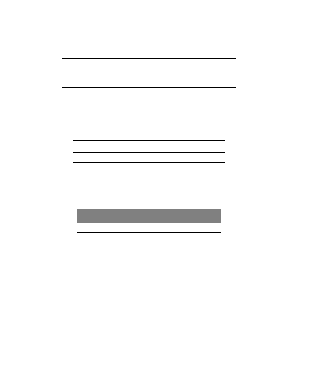
Table 4.8 defines the CTS parameters.
Table 4.8. $PASHR,CTS Format
Parameter Description Range
c1 Port identifier A, B
c2 Current CTS setting ON, OFF
hh Checksum 2-character hex
Typical CTS response:
$PASHR,CTS,A,ON*70
Table 4.9 defines a typical CTS response message.
Table 4.9. Typical CTS Response Message
Item Description
$PASHR Header
CTS Message identifier
A Port identifier
ON Current CTS setting for the related serial port
*70 Checksum
DEFAULT SETTING
CTS—ON
DAP: Doppler Averaging Interval
$PASHS,DAP,f1
This command sets the time interval for the average Doppler computation, where f1 is
the value for the output interval between 0.0 and 5.0. To use the raw Doppler value,
set f1 to 0.
The Doppler averaging period affects the noise in the computed velocity, and at
approximately 0.5, the velocity reaches its nominal value. The maximum value is
5.0*(maximum position period).
58 G12 OEM Board & Sensor Reference Manual
Page 73
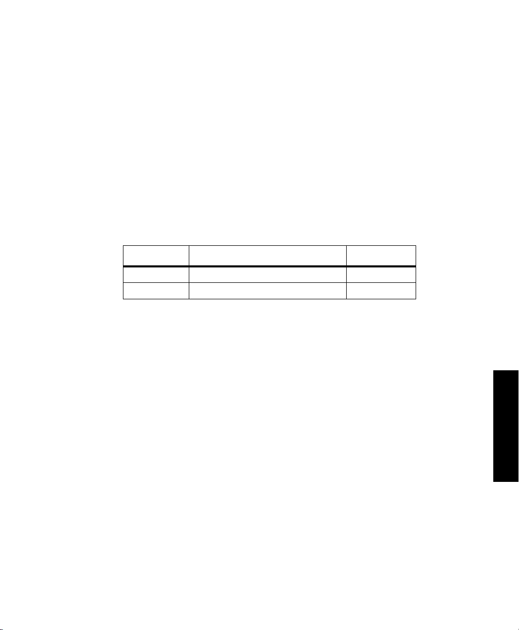
Example
Set doppler averaging time interval to 5 seconds:
$PASHS,DAP,5
$PASHQ,DAP,[c1]
This command queries the doppler averaging interval range, where c1 is the optional
port designator for the output of the response. If a port is not specified, the receiver
sends the response to the current port.
$PASHR,DAP
The response message is output in the format:
$PASHR,DAP,f1*hh
where the DAP parameters are as defined in Table 4.10.
Table 4.10. $PASHR,DAP Format
Parameter Description Range
f1 Doppler averaging interval 0.0 to 5.0
hh Checksum 2-character hex
DFO: Remote Station Status
$PASHQ,DFO,[c1]
This command queries the remote station status, where [c1] is the optional port
designator for the output of the response. If a port is not specified, the receiver
sends the response to the current port.
$PASHR,DFO
The response is in the format:
$PASHR,DFO,d1,d2,d3,d4,d5,d6,d7,{di,+/-fi1,+/-fi2}1-n
Commands
59
Page 74

Table 4.11 defines the response format:
Table 4.11. $PASHR,DFO Structure
Parameter Description Range
d1 RTCM differential mode status • 0—Not in remote mode, do not sent
remaining messages
• 2—Receiver in Remote Mode
d2 Message Status • 0—No message has been received, do not
d3 Reference Station ID 0 to 1023
d4 Reference Station Health 0 to 7
d5 Age of received message in seconds 0 to maximum age
d6 Quality factor 0 to 999
d7 Number of satellites for which the PRC
and RRC are transmitted
di PRN number (loops d7 times)
fi1 Pseudo-range correction in meters (loops
d7 times)
fi2 Range rate correction in centimeters per
second (loops d7 times)
hh Checksum 2 character, hexidecimal
send remaining messages
• 1—Message is not synchronized (message
is older than maximum age)
• 2—Message is synchronized with the last
received message
3 bytes, including +/-
3 bytes, including +/-
DSY: Daisy Chain Communications Mode
$PASHS,DSY,c1,c2;
This command redirects all characters from one serial port to the other without
interpreting them, where c1 is the source port and c2 is the destination port. Any
combination may be chosen. When daisy chain mode is in effect, the source port
can only interpret the OFF command; all other characters are redirected.
$PASHS,DSY,OFF
The OFF command disables daisy chain mode. A bi-directional daisy chain mode
(i.e. A to B and B to A at the same time) can also be enabled.
60 G12 OEM Board & Sensor Reference Manual
Page 75
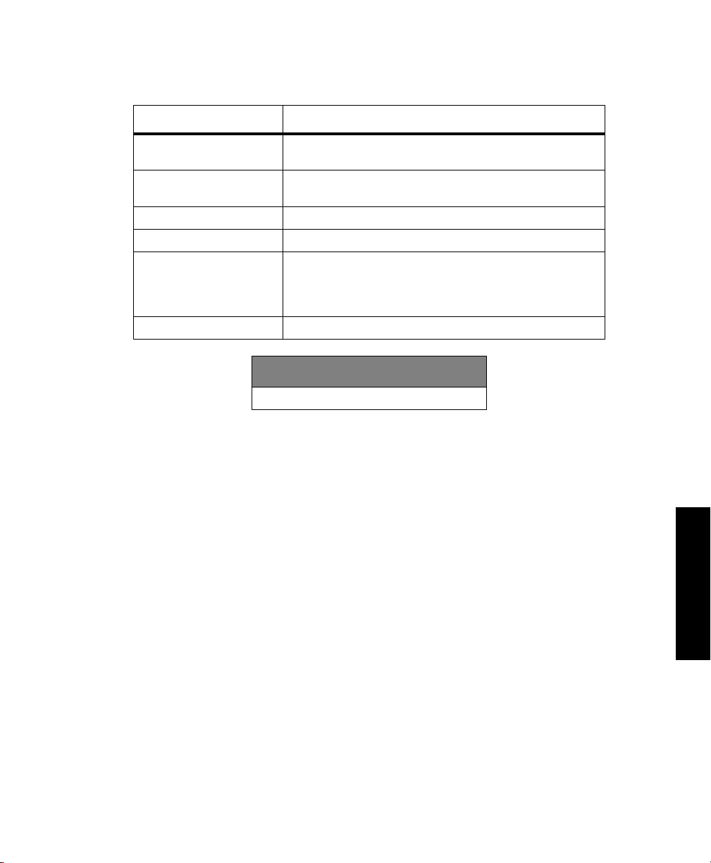
Table 4.12 lists commands and their effects.
Table 4.12. Daisy Chain Commands
Command Effect
$PASHS,DSY,A,B Redirects data going into port A over to port B. Can be issued
to either port
$PASHS,DSY,B,A Redirects data going into port B over to port A. Can be issued
to either port
$PASHS,DSY,A,OFF Turns off redirection from A. Can be issued to either port
$PASHS,DSY,B,OFF Turns off redirection from B. Can be issued to either port
$PASHS,DSY,A,B
$PASHS,DSY,B,A
$PASHS,DSY,OFF Disables daisy chain on all ports. Can be issued from any port
Both commands must be entered to enable bi-directional daisy
chain mode. If you are connecting to the G12 through port A,
enter $PASHS,DSY,B,A first. If you are interfacing to the G12
through port B, enter $PASHS,DSY,A,B first
DEFAULT SETTING
DSY—OFF
DTM: Set Reference Datum
$PASHS,DTM,UDD
This commands allow you to select a user defined datum type to use as a reference
for position computations and measurements. Parameters for the user defined
datum are entered with the $PASHS,UDD command described on page 102.
$PASHS,DTM,s1 (Extended Memory G12 only)
This command allows you to select one of two datum types to be used as a reference
for position computations and measurements; s1 specifies the datum type:
A 3 character string that defines a particular datum
USR (User Defined Datum— Parameters for user defined datum are entered
with the $PASHS,UDD command described on page 102.
61
Commands
Page 76

Table 4.13 lists the available predefined datums and associated reference
ellipsoids.
Table 4.13. Predefined Datums and Associated Reference Ellipsoids
Datum ID
ARF Clarke 1880 -143, -90, -294 ARC 1950 (Botswana, Lesotho, Malawi,
ARS Clarke 1880 -160, -8, -300 ARC 1960 (Kenya, Tanzania)
AUA Australian
AUG Australian
BOO International 1924 307, 304, -318 Bogota, Bogota Observatory (Columbia)
CAI International 1924 -148, 136, 90 Campo, S. American Campo Inchauspe
CAP Clarke 1880 -136, -108, -292 Cape (South Africa)
CGE Clarke 1880 -263, 6, 431 Carthage (Tunisia)
CHI International 1924 175, -38, 113 Chatham 1971 (Chatham, New Zealand)
CHU International 1924 -134, 229, -29 S. American Chua Astro (Paraguay)
COA International 1924 -206, 172, -6 S. American Corrego Alegre (Brazil)
EUA International 1924 -87, -96, -120 European 1950 (Western Europe: Netherlands,
EUE International 1924 -104, -101, -140 European 1950 (Cyprus)
EUF International 1924 -130, -117, -151 European 1950 (Egypt)
EUH International 1924 -117, -132, -164 European 1950 (Iran)
EUJ International 1924 -97, -88, -135 European 1950 (Sicily)
EUS International 1924 -86, -98, -119 European 1979 (Austria, Netherlands, Finland,
FAH Clarke 1880 -346, -1, 224 Oman
GAA International 1924 -133, -321, 50 Gandajika Base (Rep. of Maldives)
GEO International 1924 84, -22, 209 Geodetic Datum 1949 (New Zealand)
HJO International 1924 -73, 46, -86 Hjorsey 195 (Iceland)
INA Everest 214, 836, 303 Indian 1 (Thailand, Vietnam)
INM Everest 289, 734, 257 Indian 2 (India, Nepal, Bangladesh)
Reference
Ellipsoid
National
National
Offset in meters
(dX,dY,dZ)
Swaziland, Zaire, Zambia, Zimbabwe
-133, -48, 148 ANS66 Australian Geodetic Datum 1966
(Australia, Tasmania Island)
-134, -48, 149 ANS84 Australian Geodetic Datum 1984
(Australia, Tasmania Island)
(Argentina)
Austria, France, F.R. of Germany, Switzerland,
Denmark)
Norway, Spain, Sweden, Switzerland)
Datum Description
62 G12 OEM Board & Sensor Reference Manual
Page 77

Table 4.13. Predefined Datums and Associated Reference Ellipsoids (Continued)
Datum ID
IRL Modified Airy 506, -122, 611 Ireland 1965
KEA Modified Everest -11, 851, 5 Kertau 1948 (West Malaysia, Singapore)
LIB Clarke 1880 -90, 40, 88 Liberia 1964
LUZ Clarke 1866 -133, -77, -51 Luzon (Philippines excluding MindanoaIs.)
MAS Bessel 1841 639, 405, 60 Massawa (Eritrea, Ethiopia)
MER Clarke 1880 31, 146, 47 Merchich (Morocco)
MIN Clarke 1880 -92, -93, 122 Minna (Nigeria)
NAC Clarke 1866 -8, 160, 176 NAD27 N. American CONUS 1927 (North
NAD Clarke 1866 -5, 135, 172 AK27 N. American Alaska 1927 (Alaska)
NAE Clarke 1866 -10, 158, 187 CAN27 N. American Canada 1927 (Canada
NAH Clarke 1880 -231, -196, 482 Nahrwan (Saudi Arabia)
NAN Clarke 1866 -6, 127, 192 Central America (Belize, Costa Rica, El Salvador,
NAR GRS1980 0, 0, 0 GRS80 North American 1983
OEG Helmert 1906 -130, 110, -13 Old Egyptian
OGB Airy 1830 375, -111, 431 OSG Ordnance Survey of Great Britain 1936
OHA Clarke 1866 61, -285, -181 OLDHW Old Hawaiian
PIT International 1924 185, 165, 42 Pitcairn Astro 1967 (Pitcairn Island)
QAT International 1924 -128, -283, 22 Qatar National (Qatar)
QUO International 1924 164, 138, -189 Qornoq (South Greenland)
SAN S. American 1969 -57, 1, -41 SAMER69 S. American 1969 (Argentina, Bolivia,
SCK Bessel 1841
TIL Everest -689, 691, -46 Timbalai 1948 (Brunei, East Malaysia, Sarawak,
TOY Bessel 1841 -128, 481, 664 Tokyo (Japan, Korea, Okinawa)
USR User Defined user defined User defined
Reference
Ellipsoid
Namibia
Offset in meters
(dX,dY,dZ)
America)
including Newfoundland Island)
Guatemala, Honduras, Nicaragua, Mexico)
(England, Isle of Main Scotland, Shetland Islands,
Wales)
Brazil, Chile, Colombia, Ecuador, Guyan, Peru,
Paraguay, Venezuela, Trinidad, Tobago)
616, 97, -251 Schwarzeck (Namibia)
Sabah)
Datum Description
Commands
63
Page 78
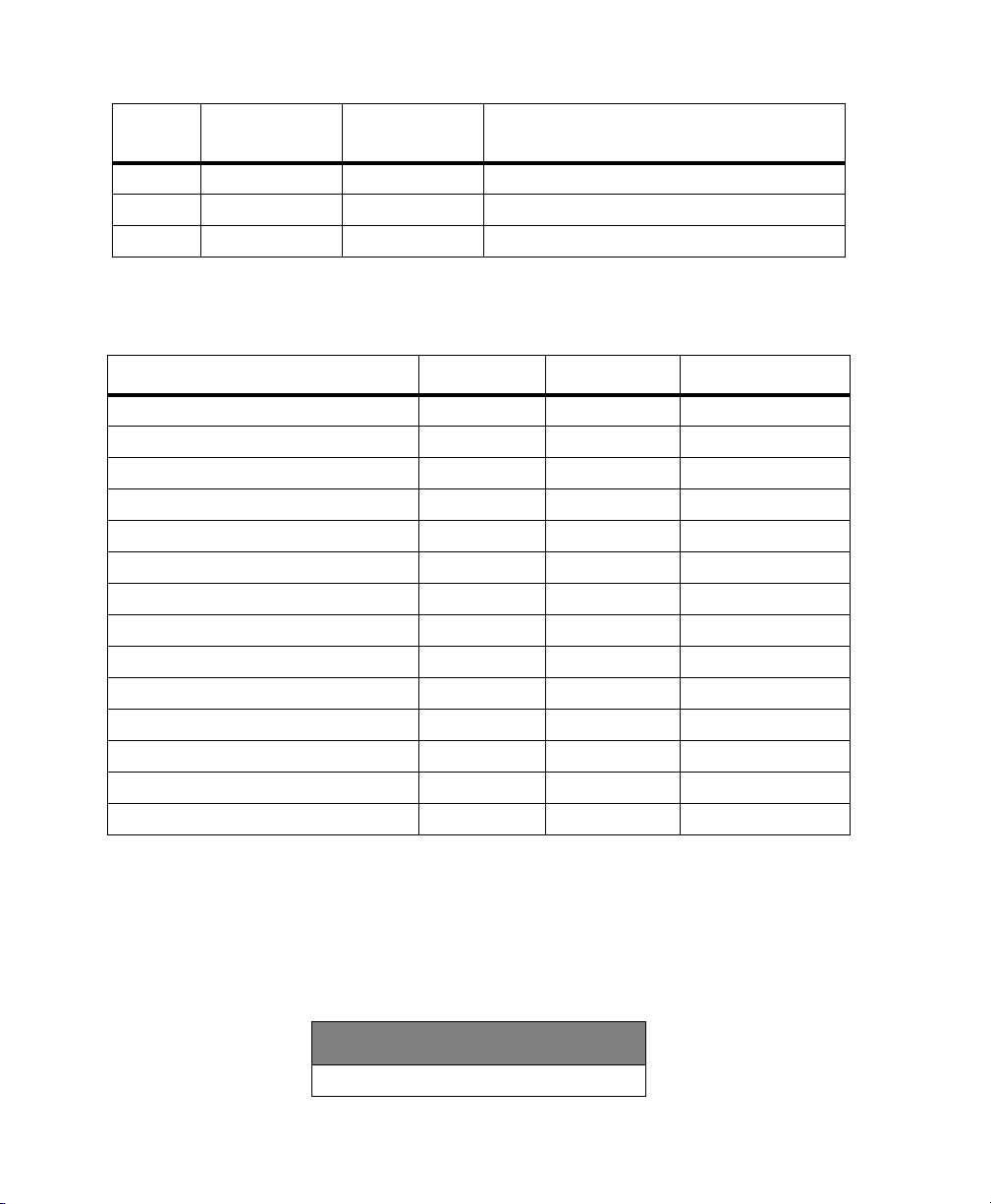
Table 4.13. Predefined Datums and Associated Reference Ellipsoids (Continued)
Datum ID
W72 WGS72 0, 0, +4.5 WGS72 World Geodetic System - 72
W84 WGS84 0, 0, 0 WGS84 World Geodetic System - 84
ZAN International 1924 -265, 120, -358 Zanderij (Surinam)
Reference
Ellipsoid
Offset in meters
(dX,dY,dZ)
Datum Description
Table 4.14 lists the predefined ellipsoids.
Table 4.14. Predefined Ellipsoids
Ellipsoid a (meters) 1/f f
Airy 1830 6377563.396 299.3249647 0.00334085064038
Modified Airy 6377340.189 299.3249647 0.00334085064038
Australian National 6378160.0 298.25 0.00335289186924
Bessel 1841 6377397.155 299.1528128 0.00334277318217
Clarke 1866 6378206.4 294.9786982 0.00339007530409
Clarke 1880 6378249.145 293.465 0.00340756137870
Everest (India 1830) 6377276.345 300.8017 0.00332444929666
Everest (W. Malaysia and Singapore) 6377304.063 300.8017 0.00332444929666
Geodetic Reference System 1980 6378137.0 298.257222101 0.00335281068118
Helmert 1906 6378200.0 298.30 0.00335232986926
International 1924 6378388.0 297.00 0.00336700336700
South American 1969 6378160.0 298.25 0.00335289186924
World Geodetic System 1972 (WGS-72) 6378135.0 298.26 0.00335277945417
World Geodetic System 1984 (WGS-84) 6378137.0 298.257223563 0.00335281066475
Example
Select New Zealand Geodetic Datum 1949 for position computation:
$PASHS,DTM,GEO
You can view the current reference datum selection with the $PASHQ,PAR
command and checking the DTM field.
DEFAULT SETTING
DTM—WGS-84
64 G12 OEM Board & Sensor Reference Manual
Page 79

$PASHQ,DTM,[c]
The associated query command queries the current datum, where c is the optional
port designator for the output of the response. If a port is not specified, the receiver
sends the response to the current port.
$PASHR,DTM
The response is in the format:
$PASHR,DTM,s*cc
s is the 3-character string, listed in Table 4.13, which denotes the current datum
setting.
DUG: GPS/UTC Time Difference
$PASHQ,DUG,[c1]
This command allows you to query the time difference between UTC time and GPS
time, where c1 is the optional port designator for the output of the response. If a
port is not specified, the receiver sends the response to the current port.
$PASHR,DUG
The response message is output in the format:
$PASHR,DUG,<Binary Data String + Checksum>
Table 4.15 defines the DUG binary data string parameters.
Table 4.15. $PASHR,DUG Binary Data String Format
Binary Type Size Content
unsigned short 2 Reference week
unsigned short 2 Reference time
unsigned short 2 GPS-UTC time (seconds)
unsigned short 2 GPS week number when the last leap second was added to GPS time
unsigned short 2 Julian day number when the last leap second was added to GPS time (1 to 365)
unsigned short 2 GPS-UTC time difference after correction (seconds)
unsigned short 2 Checksum (word)
Total bytes 14
A time step, or leap second, was added to UTC on 12-31-98. GPS time was not physically adjusted,
and is now thirteen seconds ahead of UTC. The time change is reflected in the navigation messages
generated by the individual satellites as of January 1, 1999.
65
Commands
Page 80

ERM: Set Position Error Mask Values
$PASHS,ERM,s1,d1,d2
This command allows you to set mask values for horizontal and vertical error in
relation to one of three different positioning modes:
• Autonomous (AUT)— Sets the error masks to autonomous mode
• Code-phase differential (DIF)— Sets the error mask to code-differential
mode
• Both Autonomous and Differential (ALL)— Sets equal error masks for AUT
and DIF
The s1 parameter represents the positioning mode, d1 is the horizontal error mask
value, and d2 is the vertical error mask value. The range for d1 and d2 is 1 to 6000
meters. If the calculated 99% (3 sigma) error estimate of the computed position
exceeds the set ERM value, no position will be output. The 99% position error
estimate is three times the standard deviation values reported in the GST message.
Current ERM settings appear in the $PASHQ,PAR message.
The various ERM mask parameters are utilized based on the positioning mode the receiver is
operating in. For example, in auto-differential mode (AUT,ON), based on the epoch-to-epoch
conditions, the receiver will use the respective mask parameters based on the corresponding
positioning mode of each epoch. If the receiver is generating autonomous positions (e.g. due to the
lack of current RTCM correction) the AUT mask parameters will be used until differential position
fixes are computed, which will be masked by the DIF parameters.
The horizontal position standard deviation is derived from the individual latitude and longitude
standard deviations (GST) every epoch.
Example
Enter the following command to set the error masks for autonomous mode to five
meters for horizontal measurements and ten meters for vertical measurements:
$PASHS,ERM,AUT,5,10
$PASHS,ERM,ALL,d1,d2
This command allows you to set error mask values that are applied to all positioning
modes (AUT, DIF). Error mask values set through this command are in effect
regardless of the receiver’s current positioning mode. The various ERM mask
parameters are utilized based on the positioning mode the receiver is operating in.
For example, in auto-differential mode (AUT,ON), based on the epoch-to-epoch
conditions, the receiver will use the respective mask parameters based on the
corresponding positioning mode of each epoch. If the receiver is generating
66 G12 OEM Board & Sensor Reference Manual
Page 81
autonomous positions (e.g. due to the lack of current RTCM correction) the AUT
mask parameters will be used until differential position fixes are computed, which
will be masked by the DIF parameters.
Example
Enter the following command to set the horizontal error mask to 2 meters and the
vertical error mask to 4 meters for all positioning modes:
$PASHS,ERM,ALL,2,4
DEFAULT SETTING
ERM Positioning Mode Horizontal Mask Vertical Mask
Autonomous 6000 6000
Code Differential 6000 6000
Users who currently use the RMS and standard deviation information reported in the GST message,
and who also use the PDOP mask to screen out position fixes in less than favorable conditions, may
choose to disable the additional ERM masking feature. To disable the ERM, use the default ERM
settings or issue the command: $PASHS,ERM,ALL,6000,6000.
FIX: Fixed Altitude Mode
$PASHS,FIX,d1
This command allows you to set the fixed altitude mode. It is typically used when
the receiver is in 2-D position mode or when there are not enough visible satellites
to compute a 3-D position; d1 can be 0 or 1. You can view the current setting for
fixed altitude mode with the $PASHQ,PAR command and checking the FIX field.
• Fixed Altitude Mode 0
The most recently recorded antenna altitude is used. The altitude value is
taken either from the altitude entered through the $PASHS,ALT command
or from the last altitude computed in which the VDOP value is lower than
the value entered for the VDOP mask
• Fixed Altitude Mode 1
Only the most recent altitude value entered through the $PASHS,ALT
command is used.
Commands
67
Page 82

Example
Enter the following command to set the G12 in fixed altitude mode 1:
$PASHS,FIX,1
DEFAULT SETTING
FIX—Mode 0
FUM: Fix UTM Zone
$PASHS,FUM,c1
This command enables/disables the fixing of the UTM zone, where c1 is Y (enable)
or N (disable). The default is N. This command is typically enabled when the user
is near a UTM boundary and wants to avoid the coordinate shift that occurs when
crossing from one UTM zone into another. This command is used in conjunction
with the $PASHS,FZN command which is used to select the zone to be fixed by
the FUM command.
Example
Enter the following command to enable the fixed zone setting:
$PASHS,FUM,Y
DEFAULT SETTING
FUM—N
FZN: Select Fixed UTM Zone
$PASHS,FZN,d1
This command allows you to select the UTM zone that will be held fixed, where d1
is the UTM zone number ranging from 1 to 60. This command is typically used when
the user is near a UTM boundary and wants to avoid the coordinate shift that occurs
when crossing from one UTM zone into another. This command is used in
conjunction with the command $PASHS,FUM, which holds fixed the zone selected
by the FZN command.
Example
Enter the following command to select UTM zone 10 as the zone to be held fixed:
$PASHS,FZN,10
68 G12 OEM Board & Sensor Reference Manual
Page 83

GDC: 3-D Position in User-defined Grid Coordinates
$PASHQ,GDC,[c1]
This command allows you to query for current position according to the user-defined
grid coordinate system selected through the UDG command, where c1 is the
optional port designator for the output of the response. If a port is not specified, the
receiver sends the response to the current port. The response message does not
output unless the following three conditions are met:
1. The receiver is computing positions.
2. A grid coordinate system has been selected through the UDG command.
3. The conversion from geodetic coordinates to the selected grid coordinate
system has been enabled through the GRD command.
$PASHR,GDC
The response message is output in the format:
$PASHR,GDC,m1,s2,f3,f4,d5,d6,f7,f8,f9,d10,s11,s12*hh
Table 4.16 defines the parameters.
Table 4.16. GDC Message Structure
Parameter Description Range
m1 UTC of position in hours, minutes, and decimal seconds
(hhmmss.ss)
s2 Map projection type EMER, TM83,
f3 Easting (x) of the user grid coordinate (meters) -9999999.999 to
f4 Northing (y) of the user grid coordinate (meters) -9999999.999 to
d5 Positioning mode Indicator
• 1: Autonomous position
• 2: RTCM differential, or CPD float position
• 3: Carrier Phase differential (CPD) fixed
d6 Number of GPS satellites being used 3 - 12
f7 Horizontal Dilution of Position (HDOP) 00.0 - 99.9
f8 Altitude (meters) -9999999.999 to
000000.00 to
235959.90
OM83, LC83,
STER, LC27,
Tm27, TA22
+9999999.999
+9999999.999
1, 2, 3
+9999999.999
Commands
69
Page 84

Table 4.16. GDC Message Structure (Continued)
Parameter Description Range
M Altitude units M(eters)
f9 Geoidal separation in meters w.r.t. selected datum and
Geoid Model
d10 Age of differential corrections 0 - 999
s11 Differential reference station ID 0000 - 1023
s12 Datum type W84, USR
*hh Checksum 2-character hex
-999.999 to
+999.999
Typical GDC response message:
$PASHR,GDC,015151.00,EMER,588757.623,+4136720.056,2,04,03.8,00012.123,M,
-031.711,M,14,1010,W84*2A
Table 4.17 describes the response message.
Table 4.17. Typical GDC Response Message
Item Significance
015454.00 UTM time
EMER Equatorial Mercator map projection
588757.623 User grid easting coordinate (x)
4136720.056 User grid northing coordinate (y)
2 RTCM differential position
04 Number of satellites used to compute position
03.8 HDOP
00012.123 Altitude of position
M Altitude units (M=meters)
-031.711 Geoidal separation with respect to selected datum
M Geoidal separation units (M = meters)
014 age of corrections
1010 Differential station ID
W84 Datum is WGS-84
2A Checksum
70 G12 OEM Board & Sensor Reference Manual
Page 85

GRD: Datum-to-Grid (Map Projection)— Extended Memory G12 Only
$PASHS,GRD,s1
This command allows you to enable or disable the usage of the user defined datum
to grid transformation to position outputs, where s1 is either NON (transformation
disabled) or UDG (enable user defined datum to grid transformation). The GRD
command is used in conjunction with the $PASHS,UDG command, which is used
to select the desired datum to grid transformation parameters.
Example
Enter the following command to enable the user defined to grid transformation:
$PASHS,GRD,UDG
$PASHQ,GRD,[c1]
This command allows you to query for current GRD status, where c1 is the optional
port designator for the output of the response. If a port is not specified, the receiver
sends the response to the current port.
$PASHR,GRD
The response message is output in the format:
$PASHR,GRD,s1*hh
The s1 parameter is the 3-character string indicating the current datum-to-grid
setting (NON or UDG).
HDP: HDOP Mask Value
$PASHS,HDP,d1
This command allows you to set the value of the HDOP mask, where d1 is a number
between 0 and 99.9. If the HDOP value computed by the G12 is higher than the
HDOP mask value, the receiver will automatically go into fixed altitude mode. You
can view the current HDOP mask value by entering the query command
$PASHQ,PAR and checking the HDP field.
Example
Enter the following command to set an HDOP mask value of 6:
$PASHS,HDP,6
Commands
71
Page 86
DEFAULT SETTING
HDP—4
INI: Initialize the Receiver
$PASHS,INI,d1,d2,d3
This command allows you to clear receiver memory and reset serial port baud rates,
where d1 and d2 are baud rate setting codes for ports A and B, and d3 is the memory
reset code. Table 4.18 and Table 4.19 list the code numbers and the settings
associated with them.
Table 4.18. Serial Port Baud Rate Codes
Code
0 300 5 9600
1 600 6 19200
2 1200 7 38400
3 2400 8 56800
4 4800 9 115200
Baud
Rate
Code
Baud
Rate
Table 4.19. Memory Reset Codes
Reset
Memory
Code
0 No memory reset
1 Reset internal memory (battery-backed RAM)
2 Reset external memory (data storage)— Not
functional
3 Reset internal and external memory— Not
functional
Action
72 G12 OEM Board & Sensor Reference Manual
Page 87
Example
Enter the following command to set Port A with a baud rate of 4800, Port B with a
baud rate of 19200, and to reset internal memory:
$PASHS,INI,4,6,1
The INI command is not fully functional with the G12. Since the G12 does not contain a memory area
for data storage, the reset memory code for external memory (2) has no effect on the receiver.
Resetting internal memory (1), or resetting internal and external memory (3) have the same effect.
The parameter settings for this command were maintained for the G12 in order to preserve
consistency with other Ashtech receivers.
ION: Ionospheric and Tropospheric Modeling
$PASHQ,ION,[c1]
This command allows you to query for current ionospheric data generated by the
GPS satellites, where [c1] is the optional port designator for the output of the
response. If a port is not specified, the receiver sends the response to the current
port.
Ionospheric and tropospheric modeling are enabled when the receiver is functioning in stand-alone
mode (autonomous mode), but are disabled if the receiver is set as an RTCM base or rover, since
differential corrections already compensate for ionospheric and tropospheric delays.
$PASHR,ION
The response message is output in binary format:
$PASHR,ION,<Binary Data String + Checksum>
Table 4.20 describes the elements in the binary data string:
Table 4.20. $PASHR,ION Format
Commands
Type Size Contents
float 4 a
float 4 a
float 4 a
float 4 a
float 4 b
float 4 b
float 4 b
ionospheric parameter (seconds)
0
ionospheric parameter (sec. per semicircle)
1
ionospheric parameter (sec. per semicircle)
2
ionospheric parameter (sec. per semicircle)
3
ionospheric parameter (seconds)
0
ionospheric parameter (sec. per semicircle)
1
ionospheric parameter (sec. per semicircle)
2
73
Page 88
Table 4.20. $PASHR,ION Format (Continued)
Type Size Contents
float 4 b3 ionospheric parameter (sec. per semicircle)
double 8 A
double 8 A
unsigned long 4 t
short 2 W
short 2 Dt
short 2 WN
short 2 DN day of leap second correction
short 2 Dt
short 2 WN Current GPS week number
unsigned long 4 tow Current time of week
short 2 bulwn Current GPS week number when message was
unsigned long 4 bultow Time of week when message was read
short 2 Checksum (word)
Total characters = 76 bytes
The G12 does not calculate ionospheric parameters on its own. The ionospheric data, listed in Table
4.20, are obtained from subframe 4 of the GPS navigation message.
Constant term of GPS/UTC polynomial
0
Constant term of GPS/UTC polynomial
1
Reference time
ot
reference week
nt
Delta UTC-GPS time at reference time
LS
Week of leap second correction
LSF
Delta time between GPS and UTC
LSF
read
LPS: Third-order Loop Tracking Parameters
$PASHS,LPS,d1,d2,d3
This command allows you to set third-order loop tracking parameters to optimize
loop tracking performance for a specific application, where d1 is the ratio of the
carrier loop, d2 is the carrier loop parameter, and d3 is the code loop parameter.
The carrier and code loop parameters are set independently. The G12 uses default
loop tracking values until new parameters are set through this command. Loop
tracking parameters set through this command are saved in battery-backed
memory and used until new settings are selected, battery-backed memory is
cleared, or the RST command is issued to the receiver.
74 G12 OEM Board & Sensor Reference Manual
Page 89

Example
Enter the following command to set loop tracking parameters for a low-dynamic
application:
$PASHS,LPS,1,2,2
$PASHQ,LPS,[c1]
This command allows you to query for the current loop tracking parameter settings,
where c1 is the optional port designator for the output of the response.If a port is
not specified, the receiver sends the response to the current port.
$PASHR,LPS
The response message is output in the format:
$PASHR,LPS,d1,d2,d3*hh
Table 4.21 defines the LPS parameters.
Table 4.21. $PASHR,LPS Format
Parameter Description Range
d1 Third-order ratio setting for the carrier loop:
• 0: Indicates a ratio of zero; i.e., the thirdorder ratio is disabled
• 1: Indicates a ratio of 0.1; suitable for low
acceleration rates
• 10: Indicates a ratio of 1.0; suitable for
high acceleration rates
0, 1, 10
Commands
75
Page 90

Table 4.21. $PASHR,LPS Format
Parameter Description Range
d2 Carrier loop parameter:
• 1: This setting indicates a noise
bandwidth of 0=10; suitable for static,
very low phase noise conditions
• 2: This setting indicates a noise
bandwidth of 0=25; suitable for low
dynamic, low phase noise conditions (<
2g when d1=1; < 20g when d1=10)
• 3: This setting indicates a noise
bandwidth of 0=50; suitable for high
dynamic, medium phase noise
conditions (< 6g when d1=1; < 100g
when d1=10)
d3 Code loop parameter:
• 1: Indicates noise bandwidth of 0=1.0;
suitable for fast range availability (5
sec.), medium range noise conditions
• 2: Indicates noise bandwidth of 0=0.5;
suitable for medium range availability
(10 sec.), low range noise conditions
• 3: Indicates noise bandwidth of 0=0.1;
suitable for slow range availability (50
sec.), very low range noise conditions
Typical LPS response message:
$PASHS,LPS,10,3,1,*14
Table 4.22 describes the typical LPS response message.
1, 2, 3
1, 2, 3
Table 4.22. Typical LPS Response Message
Item Description
$PASHR Header
LPS Message identifier
10 Third-order ratio setting for carrier loop (high
3 Carrier loop parameter setting (high dynamics,
1 Code loop parameter setting (fast range availability,
14 Checksum
76 G12 OEM Board & Sensor Reference Manual
acceleration rate)
medium phase noise)
medium range noise)
Page 91
DEFAULT SETTING
LPS—10, 3, 1
LTZ: Local Time Zone
$PASHS,LTZ,d1,d2
This command allows you to enter an offset value from Greenwich Mean Time
(GMT) in order to derive local time, where d1 is the number of hours and d2 is the
number of minutes that should be added to or subtracted from GMT to get local
time. The range for d1 is -13 to +13; the range for d2 is 0 to 59. Issue the command
$PASHQ,ZDA to get current local time offset values, which are displayed in the last
two fields before the checksum. See the section in this chapter entitled “NMEA
Commands/Responses” for more information on the ZDA message.
Examples
Enter the following command to add an offset of +7 hours to GMT:
$PASHS,LTZ,+7,0
Enter the following command to add an offset of -4 hours, 25 minutes:
$PASHS,LTZ,-4,25
DEFAULT SETTING
LTZ—00 hours, 00 minutes
MEM: Results of Last Memory Test
$PASHQ,MEM,[c1]
This command allows you to query for the results of the last memory self-test
performed by the G12, where c1 is the optional port designator for the output of the
response. If a port is not specified, the receiver sends the response to the current
port. The G12 performs a memory test each time it is powered up.
This message outputs without a header or message identifier. The response
message is output in the format:
h1,h2,h3,h4,h5
Commands
77
Page 92

Table 4.23 defines the parameters.
Table 4.23. Format of Response for $PASHQ,MEM
Parameter Description Range
h1 Volatile memory test result. The returned value should always be FFF0
h2 Non-volatile memory checksum result. A non-zero result indicates a
checksum failure, and the receiver will re-test this memory sector. In this
case, the third field will show the result of the non-volatile memory re-test.
A non-zero value is registered in this field the first time the receiver is used
h3 If the second field contains a non-zero value, indicating a failure in the
checksum reading of the non-volatile memory, this field will show the
results of the re-test of that memory sector. If non-volatile memory passes
the re-test, the value in this field must be 8000. If the second field contains
a zero value, indicating a good checksum, this field is ignored
h4 This field must always be zero 0000
h5 ROM checksum result. A zero value indicates the checksum is good 0000
Zero / Non-zero
FFFF / 8000
PAR: Query General Receiver Parameters
$PASHQ,PAR,[c1]
This command allows you to query for the current settings of general receiver
parameters, where c1 is the optional port designator for the output of the response.
If a port is not specified, the receiver sends the response to the current port.
The response message has a free-form Ashtech proprietary format. This message
does not have a header or message identifier as shown in the following example:
SPDA:5 SPDB:5
GPS:YYYYYYYYYYYYYYYYYYYYYYYYYYYYYYYY
PMD:1 FIX:0 ALT:+00000.00 PDP:40 HDP:04 VDP:04 ERM:6000,6000,6000,6000
PEM:05 SEM:OFF UNH:N ION:Y SAV:N DTM:W84
RTC: OFF PRT:A
NMEA: LTN POS GLL GGA VTG GSN MSG GSA GSV SAT GRS RRE TTT ZDA TCM RMC
GST GNS CRT
PRTA: OFF OFF OFF OFF OFF OFF OFF OFF OFF OFF OFF OFF OFF OFF OFF OFF
OFF OFF OFF
PRTB: OFF OFF OFF OFF OFF OFF OFF OFF OFF OFF OFF OFF OFF OFF OFF OFF
OFF OFF OFF
PER:001.0
78 G12 OEM Board & Sensor Reference Manual
Page 93

Table 4.23 describes the items in the PAR response message:
Table 4.24. PAR Response Format
Item Description Range
SPDA:5 Serial port A baud rate. Default is 5 (9600) 0 - 9
SPDB:5 Serial port B baud rate. Default is 5 (9600) 0 - 9
GPS:Y...Y Indicates which satellites (1-32) will be used (Y) or ignored (N) in
position computations. Default is Y for all satellites
PMD:1 Current position mode setting for the minimum number of
satellites required to compute a position. With default value 1, a
minimum of 3 satellites are needed to compute a position. With 3
satellites, the altitude is fixed (2-D); with 4 or more, the altitude is
computed (3-D)
FIX Current fixed altitude mode setting used when computing a 2-D
position or when there are not enough visible satellites to
compute a 3-D position. Mode 0 (default) Indicates that the
altitude value is either the most recently entered antenna altitude
($PASHS,ALT) or the most recently computed altitude in which
the VDOP value is lower than the VDOP mask
ALT Current altitude of the antenna position (meters). Default is
00000.00 meters
PDP Current PDOP (Position Dilution Of Precision) mask setting. The
receiver stops computing positions when the calculated PDOP
value exceeds the PDOP mask value. The default setting is 40
HDP Current HDOP (Horizontal Dilution Of Precision) mask setting.
The receiver stops computing positions when the calculated
HDOP value exceeds the HDOP mask value. Default is 04
VDP Current VDOP (Vertical Dilution Of Precision) mask setting. The
receiver stops computing positions when the calculated VDOP
value exceeds the VDOP mask value. Default is 04
ERM This setting indicates the mask values for horizontal and vertical
error in relation to the different positioning modes. The default is
OFF for both autonomous and differential modes which is
represented by 6000,6000,6000,6000.
PEM Current position elevation mask setting (degrees). The receiver
excludes any satellite from the position computation when its
elevation falls below the elevation mask setting. Default is 05
SEM This field indicates the secondary elevation mask angle value for
a sector of the sky defined by two azimuth angles. The default is
OFF.
Y, N
0 - 3
0, 1
-99999.99 to
+99999.99
00.0 - 99.9
00.0 - 99.9
00.0 - 99.9
1 to 6000
0° - 90°
ON, OFF
Commands
79
Page 94

Table 4.24. PAR Response Format (Continued)
Item Description Range
UNH This setting indicates whether the receiver uses (Y) or ignores (N)
unhealthy satellites. This setting is always N. The G12 never uses
unhealthy satellites in position computation
ION Indicates whether ionospheric and tropospheric modelling are
enabled (Y) or disabled (N) in position computation. Default is
always N when the receiver is in differential mode and always Y in
autonomous mode.
SAV Indicates whether user-entered parameters are saved (Y) or not
saved (N) in battery-backed memory. If user-entered parameters
are not saved, the default parameter settings are restored at the
next power cycle. Default is N
DTM Indicates whether the current geodetic reference datum is WGS-
84 (W84) or a user-defined datum (USR). Default is W84
RTC Current RTCM differential mode setting. OFF indicates RTCM is
disabled; BAS indicates base station mode; REM indicates
remote mode. Default is OFF
PRT Port assignment for sending or receiving differential corrections A, B
NMEA Lists the NMEA and Ashtech NMEA-style messages supported by
the G12
PRTA Indicates whether a given NMEA or Ashtech NMEA-style
message is enabled (ON) or disabled (OFF) for output from Port
A. Default is OFF
PRTB Indicates whether a given NMEA or Ashtech NMEA-style
message is enabled (ON) or disabled (OFF) for output from Port
B. Default is OFF
PER Output interval setting for NMEA and Ashtech NMEA-style
messages, excluding the TTT message. Default is 1 second
N
Y, N
Y, N
W84, USR
OFF, BAS, REM
CRT, GGA, GLL,
GRS, GSA, GSN,
GST, GSV, LTN,
MSG, POS, RMC,
RRC, SAT, TCM,
TTT, VTG, ZDA
ON, OFF
ON, OFF
0.05 - 999
80 G12 OEM Board & Sensor Reference Manual
Page 95
PDP: PDOP Mask Value
$PASHS,PDP,d1
This command allows you to set the value of the PDOP (Position Dilution of
Precision) mask, where d1 is a number between 0 and 99. The receiver stops
computing positions when the calculated PDOP value exceeds the PDOP mask
value. You can view the current PDOP mask setting by entering the $PASHQ,PAR
command and checking the PDP field.
Example
Enter the following command to set the PDOP mask to 30:
$PASHS,PDP,30
DEFAULT SETTING
PDP—40
PEM: Position Elevation Mask Value
$PASHS,PEM,d1
This command allows you to set elevation mask for position computation, where
d1 is 0 to 90 degrees. Default is 5 degrees. A satellite with an elevation less than
the elevation mask setting is excluded from position computations. You can view
the current elevation mask value by entering the query command $PASHQ,PAR
and checking the PEM field.
Example
Enter the following command to set the elevation mask to 15 degrees:
$PASHS,PEM,15
DEFAULT SETTING
PEM—5°
PHE: Photogrammetry Edge Mode
$PASHS,PHE,c1
This command allows you to synchronize the photogrammetry trigger to the rising
edge or the falling edge of the timing pulse, where c1 is either R (rising edge) or F
(falling edge). Default is R.
Commands
81
Page 96
$PASHQ,PHE,[c1]
This command allows you to query for the current photogrammetry edge setting,
where c1 is the optional port designator for the output of the response. If a port is
not specified, the receiver sends the response to the current port.
$PASHR,PHE
The response message is output in the format:
$PASHR,PHE,c1*hh
Table 4.25 defines the parameters.
Table 4.25. $PASHR,PHE Format
Parameter Description Range
c1 Photogrammetry edge setting R, F
hh Checksum 2-character hex
Typical PHE response message:
$PASHR,PHE,R*57
Table 4.26 describes the typical PHE response message.
Table 4.26. Typical PHE Response Message
Item Description
$PASHR Header
PHE Message identifier
R Indicates that photogrammetry events are
*57 Checksum
synchronized to the rising edge of the timing pulse
DEFAULT SETTING
PHE—R
PMD: Position Mode
$PASHS,PMD,d1
This command allows you to set the position mode. The position mode determines
the minimum number of satellites required to compute a position, whether the
receiver switches automatically from 2-D to 3-D positioning or is manually locked
82 G12 OEM Board & Sensor Reference Manual
Page 97
in 2-D or 3-D positioning mode, and, in 2-D mode, whether the altitude used is the
most recently computed “good” altitude or a fixed altitude value set by the ALT
command. Enter 0, 1, 2, or 3 for d1. You can view the current position mode by
entering the query command $PASHQ,PAR and checking the PMD field. See the
section in chapter 3 entitled “Position Modes” for more information on the position
mode settings.
• Position Mode 0: Manual 3-D Mode
Sets the receiver for 3-D position computation. The receiver must be
tracking a minimum of four satellites in order to compute a position.
• Position Mode 1: Automatic 3-D Mode
The receiver must track a minimum of three satellites to compute a
position. With three satellites, latitude and longitude are computed and
altitude is held to a fixed value (2-D positioning). With four satellites or
more, altitude is computed (3-D positioning).
• Position Mode 2: Manual 2-D Mode
The receiver must track a minimum of three satellites to compute a
position. This mode locks the receiver to 2-D positioning, meaning latitude
and longitude are computed and altitude is always held fixed regardless of
the number of satellites tracked.
• Position Mode 3: Automatic 3-D Mode
The receiver must track a minimum of three satellites to compute a
position. With 3 satellites, longitude and latitude are computed and altitude
is held fixed (2-D positioning). With 4 satellites, altitude is computed (3-D
positioning) unless the calculated HDOP value is greater than HDOP
mask setting.
Example
Enter the following command to select Position Mode 3:
$PASHS,PMD,3
DEFAULT SETTING
PMD—1
Commands
83
Page 98
POP: Position and Raw Data Update Rate
$PASHS,POP,d1
This command allows you to set the G12’s internal update rate for position and raw
data, where d1 is 10 (Hz) or 20 (Hz). Ten indicates that position and raw data will
be computed internally 10 per second; twenty indicates that position and raw data
will be computed internally 20 times per second. The default is 10. Changes made
to POP are saved with the $PASHS,SAV,Y command.
$PASHQ,POP
This command allows you to query for the internal update rate setting.
$PASHR,POP
The response message is output in the format:
$PASHR,POP,d1*hh
Table 4.27 defines the parameters.
Table 4.27. $PASHR,PHE Format
Parameter Description Range
d1 Current setting for internal update rate
(seconds)
hh Checksum 2-character hex
5, 10, 20
Typical POP response message:
$PASHR,POP,10*16
Table 4.28 describes the typical POP response message.
Table 4.28. Typical POP Response Message
Item Description
$PASHR Header
POP Message identifier
10 Indicates that position and raw data are being
*16 Checksum
updated internally at 10 Hz
DEFAULT SETTING
POP—10
84 G12 OEM Board & Sensor Reference Manual
Page 99
When positions are output at 20 Hz, the G12 can use a maximum of eight satellites to compute
positions, although the receiver can still track and generate raw data for twelve satellites. When
positions are output at 10 Hz or lower, the G12 can use up to twelve satellites to compute positions.
The G12-L supports a maximum internal update rate of 5 Hz for position and 2 hz for raw data. The
standard G12 supports a maximum internal update rate of 10 Hz for position and raw data. Both the
G12 and the G12-L can be upgraded to support an internal update rate of 20 Hz for position and raw
data, and the G12-L can be upgraded to the 10 Hz rate as well. The [W] option corresponds to the 20
Hz update rate for position and raw data; the [T] option corresponds to the 10 Hz update rate for
position and raw data.
PPO: Point Positioning
$PASHS,PPO,c
Enable/disable point positioning mode, where c is Y (enable) or N (disable). Point
positioning is an averaging algorithm that improves the stand-alone accuracy of a
static point after about 4 hours (Table 4.29).
Table 4.29. PPO Parameter Table
Item Description Range
c Enable/disable point position mode Y = enable
N = disable
Example: Enable point positioning:
$PASHS,PPO,Y
$PASHQ,PPO
Query point position.
$PASHR,PPO
The point position response message is in the format:
$PASHR,PPO,c
where c is Y or N
Commands
85
Page 100

POS: 3-D Antenna Position
$PASHS,POS,m1,c2,m3,c4,f5
This command allows you to set a 3-D antenna reference position for a differential
base station receiver. m1 is the latitude, c2 is the latitude sector, m3 is the longitude,
c4 is the longitude sector, and f5 is the altitude. Use the $PASHQ,RTC command
to verify that the desired coordinates are in effect.
$PASHS,POS,CUR
This command allows you to set the current computed position as the reference
position for a differential base station receiver. This setting is useful in some
applications which do not require absolute accuracy. Remote receivers getting
differential corrections from a base station whose reference position was entered
using this command can still compute very accurate positions relative to the base
station.
This command is not accepted when a position is not computed.
$PASHQ,POS,[c1]
This command allows you to query for the receiver’s current 3-D position, where
c1 is the optional port designator for the output of the response message. If a port
is not specified, the receiver sends the response to the current port.
$PASHR,POS
The response message is output in the format:
$PASHR,POS,d1,d2,m3,m4,c5,m6,c7,f8,,f9,f10,f11,f12,f13,f14,f15, s16*hh
Table 4.30 defines the parameters.
Table 4.30. $PASHR,POS Message Format
Parameter Description Range
d1 Indicates whether the position solution has
been computed autonomously or with the aid
of RTCM differential corrections:
• 0: Autonomous position
• 1: Corrected position
d2 Indicates the number of satellites used in
computing positions
m1 Current time (UTC) 00-235959.50
m2 Current latitude measured in degrees,
minutes, and decimal minutes
(ddmm.mmmmm)
86 G12 OEM Board & Sensor Reference Manual
0, 1
0-12
0°-90°
 Loading...