

Page 1
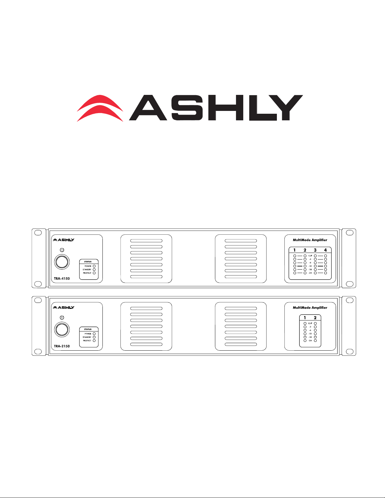
TRA-Series Amplifier
Operating Manual
Ashly Audio Inc.
847 Holt Road, Webster, NY 14580-9103
Toll Free (800) 828-6308, Telephone (585) 872-0010, FAX (585) 872-0739
www.ashly.com
All Trademarks referred to herein, are the property of their respective owners. (R8 0816)
All Rights Reserved
Page 2
Page - 2 Operator Manual – TRA Series Amplifiers
Important Safety
Instructions - 2
Introduction - 3
The TRA Series - 4
Physical Description - 5
Installation - 6
Operation - 8
Troubleshooting - 9
Spec Table - 10
Dimensions - 11
Warranty - 12
This manual uses a
Perpetual Table Of
Contents. Each page
has a copy of the
manual’s contents in a
gray box just like this
one. The section you are
in will always be bold
with the other sections
“grayed out.” The feature
allows you to jump
directly to another
section without having to
return to a Table Of
Contents page.
Important Safety Instructions
Consignes de sécurité à lire attentivement
This power amplifier can produce dangerous
output voltage, power and sound pressure
levels. In order to minimize the risk of injury,
damage, or hearing loss, please read the entire
owner’s manual.
The lightning flash with arrowhead symbol, within an equilateral triangle, is
intended to alert the user to the presence of uninsulated "dangerous voltage"
within the product's enclosure that may be of sufficient magnitude to constitute a
risk of electric shock to persons. The exclamation point within an equilateral
triangle is intended to alert the user to the presence of important operating and
maintenance instructions in the literature accompanying the device.
1. Read these instructions.
2. Keep these instructions.
3. Heed all warnings.
4. Follow all instructions.
5. To reduce the risk of fire or electric shock, do not expose
this apparatus to rain or moisture.
6. Do not use this apparatus near water.
7. Clean only with dry cloth.
8. Do not block any ventilation openings. Install in
accordance with the manufacturer’s instructions.
9. Do not install near any heat sources such as radiators, heat
registers, stoves, or other apparatus (including amplifiers)
that produce heat.
10. Do not defeat the safety purpose of the polarized or
grounding-type plug. A polarized plug has two blades
with one wider than the other. A grounding type plug has
two blades and a third grounding prong. The wide blade
or the third prong are provided for your safety. If the
provided plug does not fit into your outlet, consult an
electrician for replacement of the obsolete outlet.
11. Protect the power cord from being walked on or pinched
particularly at plugs, convenience receptacles, and the
point where they exit from the apparatus.
12. Only use attachments/accessories specified by the
manufacturer.
13. Use only with the cart, stand, tripod, bracket, or table
specified by the manufacturer, or sold with the
apparatus. When a cart is used, use caution when
moving the cart/apparatus combination to avoid injury
from tip-over.
14. Unplug this apparatus during lightning storms or when
unused for long periods of time.
15. Refer all servicing to qualified service personnel.
Servicing is required when the apparatus has been
damaged in any way, such as power-supply cord or plug
is damaged, liquid has been spilled or objects have fallen
into the apparatus, the apparatus has been exposed to
rain or moisture, does not operate normally, or has been
dropped.
Le symbole de la flèche dans un triangle équilateral symbolisant la foudre est
prévu pour sensibiliser l’utilisateur à la présence de tension de voltage non isolée
à l’intérieur de l’appareil. Elle pourrait constituer un danger de risque de
décharge électrique pour les utilisateurs. Le point d’exclamation dans le triangle
équilatérale alerte l’utilisateur de la présence de consignes qu’il doit d’abord
consulter avant d’utiliser l’appareil.
1. Lisez ces instructions.
2. Conservez ces instructions.
3. Observez les avertissements.
4. Suivez ces instructions.
5. Pour réduire le risque de feu ou la décharge électrique,
6. Ne pas utiliser l’appareil près de l’eau.
7. Le nettoyer à l’aide d’un tissus sec.
8. Ne pas bloquer les ouvertures de ventilation, installer
9. Eloigner des sources de chaleur tel: radiateurs,
10. Ne pas modifier ou amputer le système de la mise à
11. Protéger le cordon de secteur contre tous bris ou
12.
13. N’utiliser qu’avec les systèmes de fixation,chariots,
14. Débrancher l’appareil lors des orages électriques ou si
15. Un entretient effectué par un centre de service accrédité
Cet amplificateur de puissance peut produire un
voltage et une pression acoustique qui pourrait être
dangereuse ou pourrait meme causer des
problêmes ou perte accuité auditive. Consultez le
manuel d’instruction et observez les consignes.
ne pas exposer cet appareil pour pleuvoir ou l'humidité.
selon les consignes du fabricant.
fourneaux ou autres appareils qui produisent de la
chaleur.
terre. Une prise avec mise à terre comprend deux lames
dont une plus large ainsi qu’une mise à terre: ne pas la
couper ou la modifier. Si la prise murale n’accepte pas la
fiche, consulter un électricien pour qu’il remplace la prise
désuète.
pincement qui pourraient l’endommager, soit à la fiche
murale ou à l’appareil.
N’employer que les accessoires recommandés par le
fabricant.
trépied ou autres, approuvés par le fabricant ou vendus
avec l’appareil.
inutilisé pendant une longue période de temps.
est exigé si l’appareil a été endommagé de quelque
façon: si il a été exposé à la pluie,, l’humidité ou s’il ne
fonctionne pas normalement ou qu’il a été échappé.
Copyright© 2016 – Ashly Audio Inc.
Page 3

Operator Manual – TRA Series Amplifiers Page - 3
Important Safety
Introduction
Congratulations on your purchase of an Ashly TRA-Series amplifier. The TRA-Series is
made up of high-efficiency, amplifiers incorporating the latest technologies. We are
confident that you will be pleased with the high performance, superb sound quality,
reliability, and more.
About Ashly
Ashly Audio was founded in 1974 by a group of recording engineers, concert sound
professionals, and electronics designers. The first products were elaborate custom consoles
for friends and associates, but business quickly spread to new clients and the business
grew. The philosophy we established from the very beginning holds true today: to offer
only the highest quality audio tools at an affordable cost to the professional user – ensuring
reliability and long life. More than thirty years later, Ashly remains committed to these
principles.
Ashly’s exclusive Five Year, Worry- Free Warranty remains one of the most liberal
policies available on any commercial- grade product. The warranty covers every product
with the Ashly brand name, and is offered at no extra cost to you, our customer.
Instructions - 2
Introduction - 3
About Ashly
Safety
FCC Compliance
The TRA Series - 4
Physical Description - 5
Installation - 6
Operation - 8
Troubleshooting - 9
Spec Table - 10
Dimensions - 11
Warranty - 12
FCC Compliance
This device complies with part 15 of the FCC Rules. Operation is subject to the following
two conditions:
1. This device may not cause harmful interference
2. This device must accept any interference received, including interference
that may cause undesired operation.
Note: This equipment has been tested and found to comply with the limits for a Class B
digital device, pursuant to part 15 of the FCC Rules. These limits are designed to provide
reasonable protection against harmful interference in both a commercial and residential
installation. This equipment generates, uses and can radiate radio frequency energy and, if
not installed and used in accordance with the instructions, may cause harmful interference
to radio communications. However, there is no guarantee that interference will not occur
in a particular installation. If this equipment does cause harmful interference to radio or
television reception, which can be determined by turning the equipment off and on, the
user is encouraged to try to correct the interference by one or more of the following
measures:
- Reorient or relocate the receiving antenna.
- Increase the separation between the equipment and receiver.
- Connect the equipment into an outlet on a circuit different from that to which the receiver
is connected.
- Consult the dealer or an experienced radio/TV technician for help.
All Rights Reserved
Page 4
Page - 4 Operator Manual – TRA Series Amplifiers
Important Safety
Instructions – 2
Introduction - 3
The TRA Series - 4
Protection
Physical Description - 5
Installation - 6
Operation - 8
Troubleshooting - 9
Spec Table - 10
Dimensions - 11
Warranty - 12
The TRA Series
TRA-Series amplifiers are high-efficiency, amplifiers incorporating the latest amplifier
technologies.
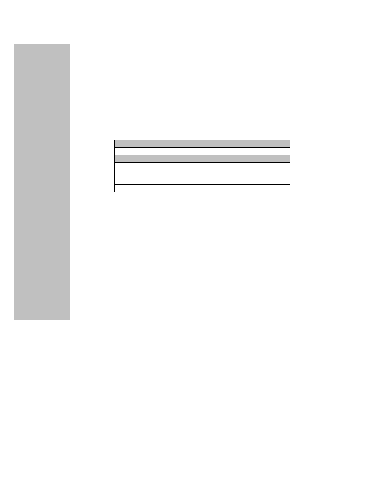
The series provides a power range of 75 to 150 watts per channel at 4 ohms (20Hz-20kHz,
1% THD). The TRA series is available in 2 and 4 channel versions at two power points. All
models will drive 4 or 8 ohm loads as well as 25V, 70V, and 100V constant voltage lines.
All models are 2RU, with the two and four channel versions weighing 19.5 pounds and 29.5
pounds respectively. All TRA amplifiers utilize a state-of-the-art, efficient, high speed
switched mode power supply and offer remote power on/off among the standard features.
TRA-Series Power Ratings (per channel)
Stereo Constant Voltage
Model 8Ω 4Ω 25/70V/100V
TRA-2075 40 W 75 W 75 W
TRA-4075 40 W 75 W 75 W
TRA-2150 80 W 150 W 150 W
TRA-4150 80 W 150 W 150 W
Input connections are via 3-pin Euroblock connectors.
Output connectors are screw terminal strips.
Controls on the rear panel include: Gain and channel attenuation.
Protection
TRA-Series Amplifiers come standard with several protection circuits:
Output over-current protection - The output current is limited to safe levels
regardless of load.
DC output protection - The amplifier is switched off if more than 2 volts of
dc is present on the output. The amplifier will automatically restart after 5
seconds (if no fault remains). The protect LED is lit as well as the clip LED of
the affected channel(s).
Main supply rail overvoltage protection - The amplifier is switched off if
the main supply rails have too high of a voltage. The amplifier will
automatically restart after 5 seconds (if no fault remains). The protect LED is
lit as well as the clip LED of the affected channel(s).
Chassis internal temperature monitoring - The amplifier is switched off
when the internal ambient temp reaches 70º C. The amplifier will again switch
on when the internal ambient temp reaches 55º C. The protect LED is lit as
well as the clip LED of ALL channels.
Inrush limiting - The turn-on current is limited. This is active during initial
startup as well as when exiting standby mode.
Mains fuse - There is a 5 amp time delay fuse.
Copyright© 2016 – Ashly Audio Inc.
Page 5
Operator Manual – TRA Series Amplifiers Page - 5
Important Safety
Physical Description
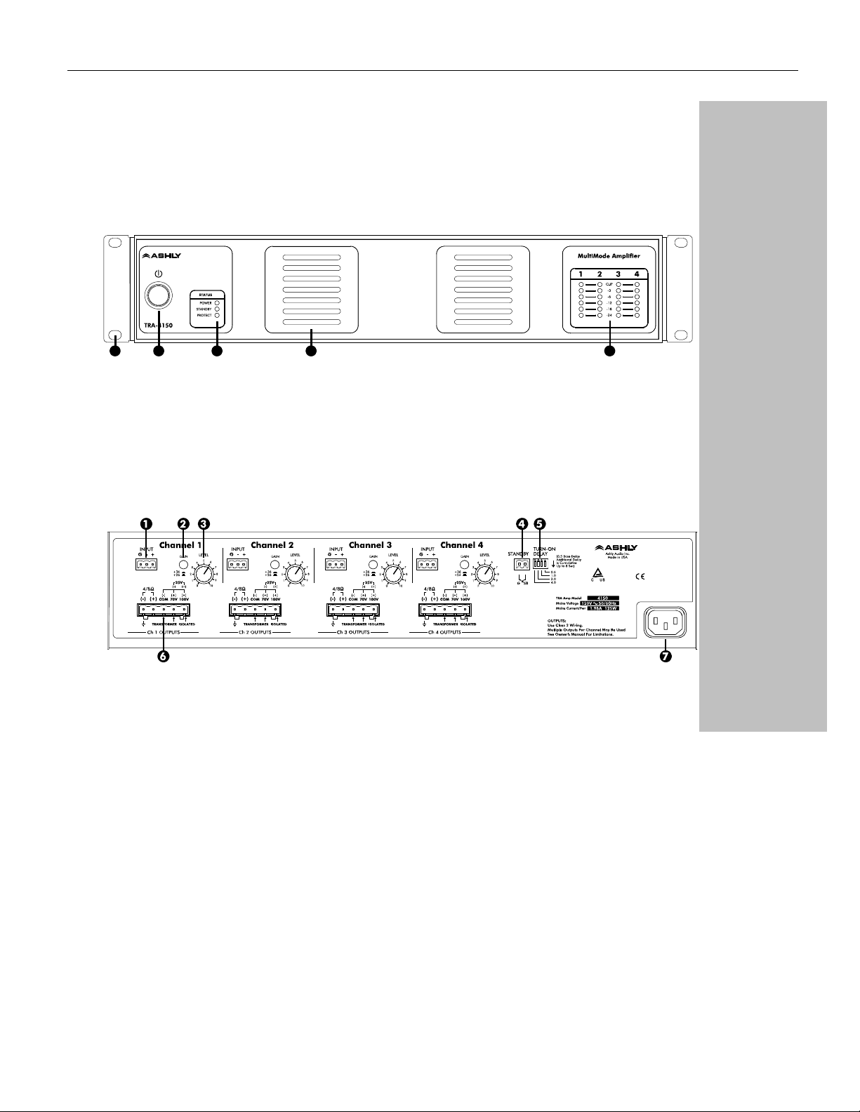
TRA-Series models generally have the same physical design, though there are obvious
differences between two and four channel versions. The model number is indicated on the
left side of the front panel
Amplifier Front Panel
21 3 4 5
1. Mounting Holes – For rack mounting.
2. Power Switch – Switches the unit on or off
3. Status LEDs – Indicate status of Power,
Standby, and Protect
4. Air Vents
Amplifier Rear Panel
5. Channel LEDs – The Sig LED will begin to
light when the output voltage reaches
approximately 0.3 volts. When clipping occurs
the Clip LED will light.
Instructions – 2
Introduction - 3
The TRA Series - 4
Physical Description - 5
Front Panel
Rear Panel
Installation - 6
Operation - 8
Troubleshooting - 9
Spec Table - 10
Dimensions - 11
Warranty - 12
1. 3-Pin Euroblock Input Connectors – These
connectors are used for all input signals.
2. Gain Switch – sets the amplifier gain to +36dB
or +26dB sensitivity.
3. Channel Attenuators – These knobs adjust
the attenuation of the input signal of each
channel from to 0.
Items 1-4 are identical on all channels of all
TRA-Series amplifiers, 2 or 4 channel.
4. Standby Connector – This 2-Pin Euroblock
connector provides for remote standby
switching. The Power switch must be in the On
position for the Standby connector to be active.
5. Delay Switches – These switches provide turn
on delay when the Standby connector is used.
The switches are additive, providing as much
as 7.5 seconds of delay
6. Screw Terminal Output Connectors – These
connectors provide the output signal for each
channel. The positive 4/8 (+) and negative () connectors should be used for low-impedance
applications. For constant voltage 70V or 100V
applications, connect the negative wire (-) of
your system to the C (common) terminal and
the positive (+) wire to the appropriate Constant
Voltage output. For 25V, wire as shown.
7. Mains Connector - Connection to the mains is
via this 3-Prong IEC connector
WARNING: Do not remove the mains connector ground.
All Rights Reserved
Page 6

Page - 6 Operator Manual – TRA Series Amplifiers
Important Safety
Instructions – 2
Introduction - 3
The TRA Series - 4
Physical Description - 5
Front Panel
Rear Panel
Installation – 6
Requirements
Typical Applications
Connectors & Polarity
Operation - 8
Troubleshooting - 9
Spec Table - 10
Dimensions - 11
Warranty - 12
Installation
TRA-Series amplifiers are designed for use in both fixed and mobile sound systems. Each
amplifier is shipped (unless otherwise specified) with the following factory settings:
Front panel: Rear panel:
On/Off Switch = Off
Attenuators =
Before connecting to mains power, make sure that the switches are set to the configuration
needed for your particular application. Always switch the amplifier off before making any
changes to the settings. Failure to do so could result in damage to the unit or other components
in your system. CAUTION: When mounting or connecting the amplifier, always disconnect it
from the mains. Use four screws and washers when mounting the amplifier to the front rack
rails. Rear support is also recommended, especially for mobile or touring use. To reduce the
risk of fire or electric shock, do not expose this apparatus to rain or moisture.
Gain Selector = +26 dB
Requirements
TRA-Series amplifiers have specific physical, electrical and signal requirements for proper
operation. These requirements will vary depending on your specific application, setup, and
the settings on the amplifier. When setting up and testing your system, please take special
care to double check all connections and settings. Please refer to the specifications section
of this manual for specific input, output and other figures.
Copyright© 2016 – Ashly Audio Inc.
Page 7
Operator Manual – TRA Series Amplifiers Page - 7
Typical Applications
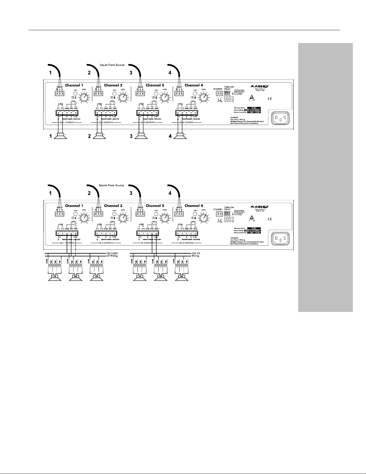
TRA-Series amplifiers offer many output options. In this illustration, the 4-channel
amplifier is receiving two stereo signals and is driving two pairs of stereo speakers.
Important Safety
Instructions – 2
Introduction - 3
The TRA Series - 4
Physical Description - 5
Installation – 6
Requirements
Typical Applications
Connectors & Polarity
Operation - 8
Troubleshooting - 9
Spec Table - 10
Dimensions - 11
Warranty - 12
TRA-Series amplifiers are specifically designed to drive transformer isolated 25V, 70V,
or 100V constant voltage (CV) lines. This illustration example shows a 4 channel TRA
driving a 70V CV line and 25V line (with two channels still available). Always make sure
that the total wattage draw from all the speakers on a CV line does not exceed the rated
output of the channel to which they are connected.
Connectors & Polarity
TRA-Series amplifiers utilize professional euroblock audio connectors. For the inputs, 3pin Euroblock connectors are utilized with their polarity clearly marked on the amplifier’s
rear panel. Outputs are also euroblock connectors, with polarity clearly marked on the
chassis.
NOTE: It is possible to simultaneously drive loads connected to the 8/4 ohm output
AND the 25/70/100 volt outputs of a particular amplifier channel. However, care must
be taken to ensure that the combined load is not less that the 4 ohm maximum. If you
are unsure as to how to determine the combined load, please contact Ashly.
All Rights Reserved
Page 8

Page - 8 Operator Manual – TRA Series Amplifiers
Important Safety
Instructions – 2
Introduction - 3
The TRA Series - 4
Physical Description - 5
Installation – 6
Operation – 8
Troubleshooting - 9
Spec Table - 10
Dimensions - 11
Warranty - 12
Operation
The amplifier’s On/Off Switch is a rocker-type switch located on the left side of the front
panel. Turning on the amplifier initiates start-up by activating the inrush current limiter.
When using the remote On/Off function, the main On/Off switch must remain in the On
position. See page 11 for more information on remote On/Off connections.
NOTE: The power switch does NOT isolate the appliance from mains. Make sure the mains
power socket or an alternative disconnect device is near by and easily accessible. When the
product is connected to mains, the line-filter and the input of the fuse are energized.
Copyright© 2016 – Ashly Audio Inc.
Page 9
Operator Manual – TRA Series Amplifiers Page - 9
A
Important Safety
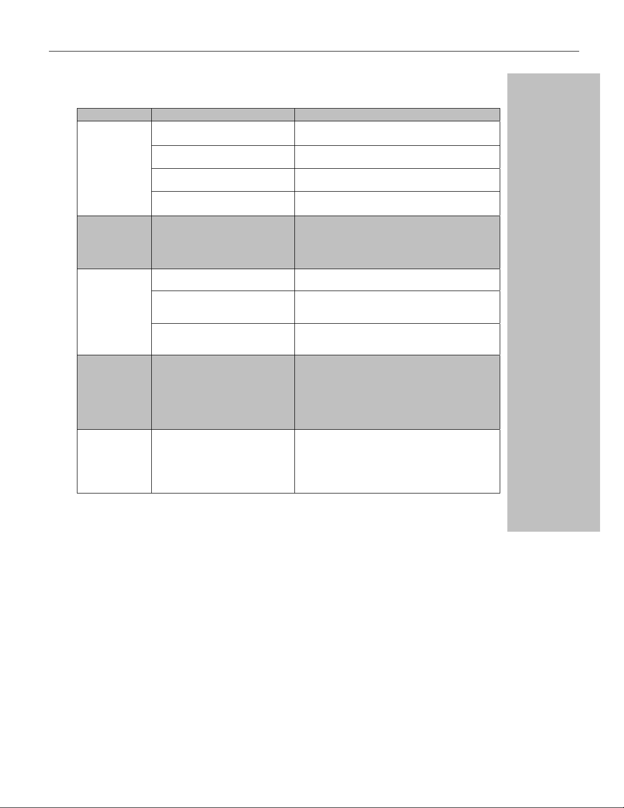
Troubleshooting
Situation Indication Action
No Sound
No Channel
Separation
Distorted Sound Power LED is lit
Hiss Hiss Unplug the amplifier input to confirm that the hiss is
Squeals and
Feedback
Signal LED not lit
Clip LEDs not lit
Signal LED not lit Make sure the signal source is operating and try another
Signal LEDs responding to signal level Check the speaker wiring for breaks.
Signal LEDs show red (Protect Mode) Overheating will cause protective muting. Check for
No Channel Separation Check the mode indicators on the front panel and make
Signal LEDs responding to signal level The signal source might be clipping. Keep the volume
Clip LEDs not lit Keep the volume pots at least halfway up and try
Squeals and Feedback Microphone feedback should be eliminated with mixer
Check AC plug. Confirm that AC outlet works by plugging
in another device.
cable. Check position of channel attenuators.
Try another speaker and cable.
proper ventilation.
sure the mode selector on the rear panel is in the two
channel (stereo) position. Make sure other equipment in
the signal path such as mixers and preamps are set for
stereo, not mono
faulty speaker or a loose connection could cause this.
Check the wiring and try another speaker.
pots at least halfway up so that the source does not have
to be overdriven.
changing input sensitivity with the gain selector on the
rear.
coming from the source or from a device upstream. Erratic
or popping noises indicate an electronic fault in the
offending unit. To keep the noise floor low, operate the
primary signal source at full level, without clipping. Avoid
boosting the signal further between the source and the
amplifier.
controls. If noise continues to build up with no microphone
gain, there is a serious fault in the signal processors or
cables. Working in succession from the signal source
towards the amplifier and check each device in the signal
path by reducing its gain or by unplugging it.
Instructions – 2
Introduction - 3
The TRA Series - 4
Physical Description - 5
Installation – 6
Operation – 8
Troubleshooting - 9
Spec Table - 10
Dimensions - 11
Warranty - 12
All Rights Reserved
Page 10

Page - 10 Operator Manual – TRA Series Amplifiers
A
Important Safety
Instructions – 2
Introduction - 3
The TRA Series - 4
Physical Description - 5
Installation – 6
Operation – 8
Troubleshooting - 9
Spec Table - 10
Dimensions - 11
Warranty - 12
Spec Table
Power Output Per Channel
8 ohms, 80 Hz - 20 kHz, 1% THD 40 W 40 W 80 W 40 W
4 ohms, 80 Hz - 20 kHz, 1% THD 75 W 75 W 150 W 150 W
25V/70V/100V CV, 80 Hz - 20 kHz, 1% THD 75 W 75 W 150 W 150 W
Line Current Draw (all channels driven @4Ω)
Standby 37mA 39mA 89mA 102mA
Idle 320mA 565mA 370mA 660mA
1/8th Power Pink Noise 0.70A 1.25A 1.10A 1.95A
1/3 Power Sine Wave 1.23A 2.25A 2.10A 3.80A
Thermal Dissipation (all channels driven @4Ω)
Standby (BTU /hr) 13 15 14 23
Idle (BTU/hr) 61 113 72 137
1/8th Power Pink Noise (BTU/hr) 73 145 111 211
1/3 Power Sine Wave (BTU/hr) 85 150 126 263
Signal to Noise (20 Hz-20 kHz, unweighted):
Voltage Gain: 26 dB, 36 dB sensitivity (selectable)
Output Circuitry: Class D Class D Class D Class D
Frequency Response 80 Hz - 20 kHz –3dB +/- 1.0 dB (due to internal 80 Hz HPF)
Distortion (SMPTE, typical) < 0.5% - 8Ω load, 10dB below rated power
Distortion (THD-N, typical) < 0.5% - 8Ω load, 10dB below rated power, 20Hz-20kHz
Damping Factor - 8 ohm load, < 1 kHz > 200 into 8Ω
Input Impedance 20 kΩ, balanced
Maximum Input Level: +21 dBu
Input Impedance 20kΩ balanced
Cooling Convection
Front Panel Indicators per channel Clip & Signal
Front Panel Indicators overall power, standby, protect
Attenuators Per channel: front panel
Input Connectors, each channel 3- Pin Euroblock
Output connectors, each channel Screw terminals
mplifier Protection Output Overcurent, DC Output, Mail Supply Rail Overvoltage
Power Cable Connector 3-Prong IEC
Dimensions 19” x 3.5” x 12” (483mm x 89mm x 305mm)
Net Weight 19.5 lbs (8.85kg) 29.5 lbs (13.4kg) 19.5 lbs (8.85kg) 29.5 lbs (13.4kg)
All Specifications Subject to Change or Improvement Without Notice.
TRA-2075 TRA-4075 TRA-2150 TRA-4150
>100 dB >100 dB >103 dB >103 dB
Chassis Temperature, Inrush Limiting, Mains Fuse
Copyright© 2016 – Ashly Audio Inc.
Page 11
Operator Manual – TRA Series Amplifiers Page - 11
Important Safety
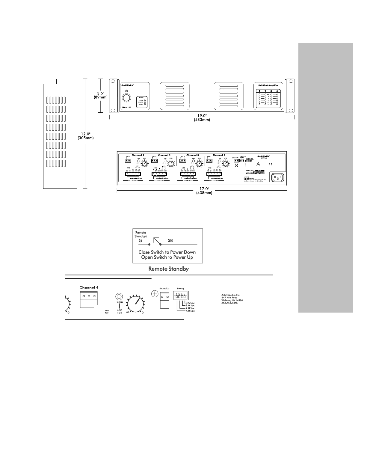
Amplifier Dimensions
All TRA Series amplifiers share the same dimensional measurements:
Instructions – 2
Introduction - 3
The TRA Series - 4
Physical Description - 5
Installation – 6
Operation – 8
Troubleshooting - 9
Spec Table - 10
Dimensions - 11
Warranty - 12
Remote Power Connections
All Rights Reserved
Page 12

Page - 12 Operator Manual – TRA Series Amplifiers
Important Safety
Instructions – 2
Introduction - 3
The TRA Series - 4
Physical Description - 5
Installation – 6
Operation – 8
Troubleshooting - 9
Spec Table - 10
Dimensions - 11
Warranty - 12
Ashly Audio Inc. Limited Warranty (USA ONLY)
(For other countries, please contact your respective distributor or dealer from where the unit was first purchased.)
For units purchased in the USA, warranty service for this unit shall be provided by
ASHLY AUDIO, INC. in accordance with the following warranty statement:
ASHLY AUDIO, INC. warrants to the owner of this product that it will be free from defects
in workmanship and materials for a period of FIVE years from the original date of purchase,
with the exception of touch-screen displays and motorized faders which are warrantied for
THREE years from the original date of purchase.
ASHLY AUDIO INC. will without charge, repair or replace at its discretion any defective
product or component parts upon prepaid delivery of the product to the ASHLY AUDIO,
INC. factory service department, accompanied with a proof of original date of purchase in
the form of a valid sales receipt. This warranty gives you specific legal rights, and you may
also have other rights, which vary from state to state.
EXCLUSIONS: This warranty does not apply in the event of misuse, neglect or as a result of
unauthorized alterations or repairs made to the product. This warranty is void if the serial
number is altered, defaced, or removed. ASHLY AUDIO reserves the right to make changes
in design, or make additions to, or improvements upon, this product without any obligation
to install the same on products previously manufactured.
Any implied warranties which may arise under the operation of state law shall be effective
only for FIVE years (THREE years for touch-screen displays or motorized faders) from the
original date of purchase of the product. ASHLY AUDIO, INC. shall be obligated to only
correct defects in the product itself. ASHLY AUDIO, INC. is not liable for any damage or
injury which may result from or be incidental to or a consequence of such defect. Some
states do not allow limitations on how long an implied warranty lasts, or the exclusion, or
limitation of incidental or consequential damages, so the above limitations or exclusions may
not apply to you.
OBTAINING WARRANTY SERVICE:
For warranty service in the United States, please follow this procedure:
1.) Return the product to ASHLY AUDIO, INC, freight prepaid, with a written statement
describing the defect and application that the product is used in. ASHLY AUDIO,
INC. will examine the product and perform any necessary service, including
replacement of defective parts, at no further cost to you.
2.) Ship your product to:
Ashly Audio Inc.
Attn: Service Department
847 Holt Road
Webster, NY 14580-9103
Copyright© 2016 – Ashly Audio Inc.
 Loading...