

Page 1
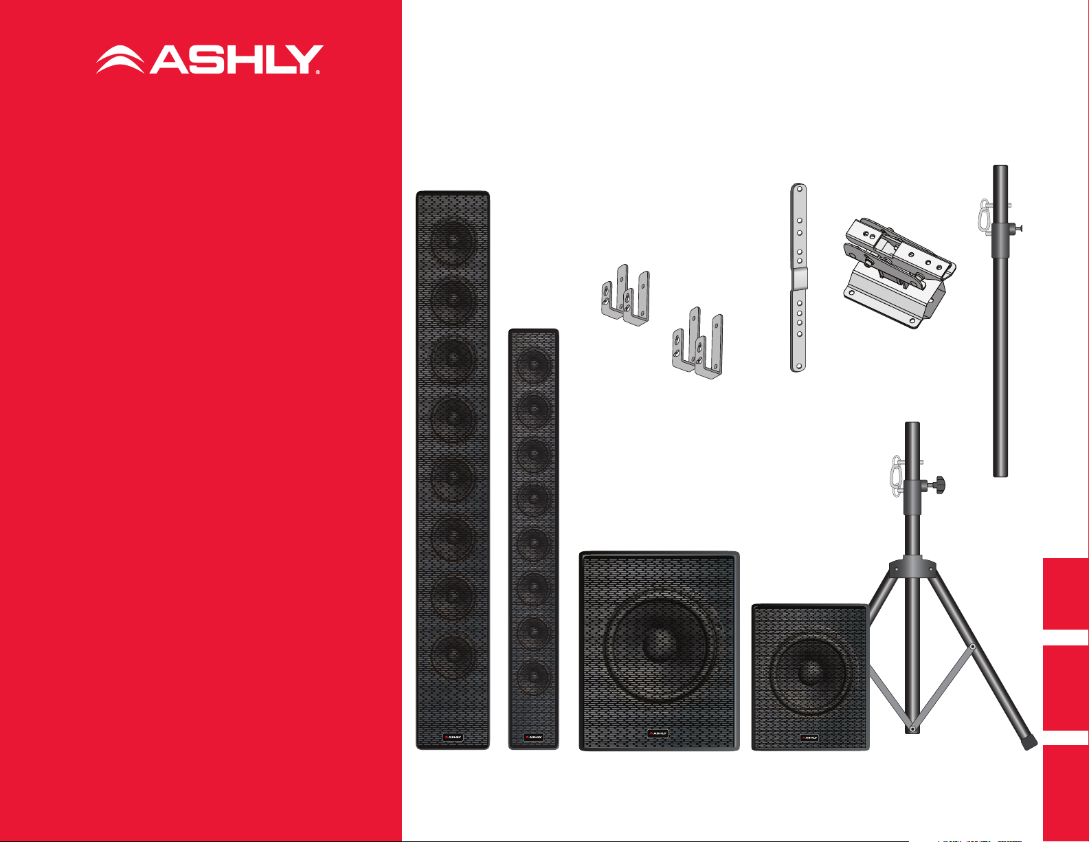
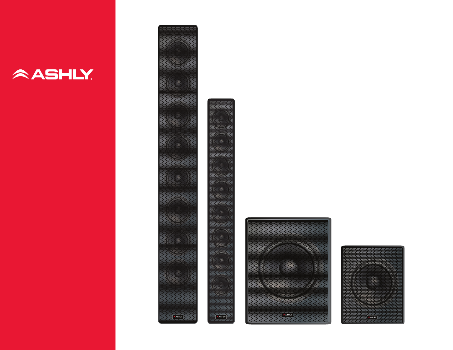
IS 2.8P
8 x 2-inch
column speakers
IS 3.8P
8 x 3-inch
column speakers
SP 12.1P
Twelve-inch subwoofer
SP 8.1P
Eight-inch subwoofer
Operating and
Installation Manual
IS-TR7B
Tripod mount for IS 2.8P or IS 3.8P
IS-PM1B
1 foot pole mount for SP subs
IS-PM6B
Pole mount for IS 2.8P or IS 3.8P + SP 12.1P
IS-TWM
Tilt wall mount for IS 2.8P or IS 3.8P
IS-FWM
Flush wall mount for IS 2.8P or IS 3.8P
IS-JP2
Joining bracket for two IS 2.8Ps or IS 3.8Ps
M10-SP
Fly bolts for SP 1.8P
IS-TWM IS-FWMIS-JP2
1
Page 2

IS Series + SP Series Operating Manual
Safety and Operation Precautions.
1. Heed all warnings; follow all instructions.
2. Refer all servicing to qualified personnel.
Servicing is required when the apparatus has
been damaged in any way.
Installation and Mounting
3. To prevent inductive effects from causing
hum and/or noise, loudspeaker lines should
not be laid together with other electric
cables, microphone or line level signal
cables connected to amplifier inputs.
4. To ensure proper sound reproduction,
correct loudspeaker polarity is necessary.
Check “+” and “−” polarity at both the
amplifiers and the IS Series speakers.
5. Make sure loudspeaker lines are not shorted
before turning the amplifier on.
6. The entire audio system must comply with
the current local standards and regulations
regarding electrical systems.
7. Ashly recommends this product only
be permanently installed by licensed,
professional installers (or specialized firms)
who can ensure a correct installation and
certified by a local inspector.
8. Do not install near any heat sources such
as radiators, heat registers, stoves, or
other apparatus (including amplifiers) that
produce heat.
9. Use only with mounts or brackets specified
by Ashly Audio.
10. Check the suitability of the support surface
to which the product is anchored (wall,
ceiling, structure, etc.) and the attachment
components (wall plugs, screws, brackets
etc.) to confirm that they are in compliance
with requirements set forth by local building,
safety and electrical codes.
11. Make sure all connections have been made
correctly and the loudspeaker input voltage
is suitable for the amplifier output.
12. Protect loudspeaker lines from damage.
Make sure they are positioned in a way that
they cannot be stepped on or crushed by
objects.
13. Make sure that no objects or liquids can get
into this product, as this may cause a short
circuit.
14. Place the SP 8.P/SP 12.1P subwoofer on a
flat, rigid and anti-skid surface.
Pole, Tripod Mount, Joining Plate
15. Please use Ashly IS-TR7B tripod mount for
IS 2.8P and IS 3.8P speakers. If mounting
the speakers on top of the SP 8.1P or
SP12.1P subwoofer, use only the IS PM1B or
IS PM6B speaker poles.
16. When pole or tripod mounting IS column
speakers, make certain units are placed in a
safe and secure area which is free from foot
traffic or other activities which could cause
accidental tripping or stand collapse.
17. Open the mount’s three “legs” as wide as
possible to ensure its stability.
18. Tighten the height-adjustment bolt firmly.
19. Insert the safety pins on both the fixed and
extendable parts of the tripod or pole.
20. Make sure the the Ashly IS-JP2 accessory
joining plate used to connect to IS speakers
is securely attached.
21. When using two IS speakers joined by an IS-
JP2 vertical mounting plate, pay particular
attention to tripod placement. Confirm
that the tripod mounts’ three legs are fully
extended. Remember that the center
of gravity is higher than with a single IS
speaker.
22. For flying the SP8.1P: Use only the M10-
SP eye bolts. You should consult with a
licensed contractor prior to flying the
SP8.1P to ensure compliance with local
safety regulations. Also, do not hang other
speakers from a suspended SP8.1P. That will
exceed the load capacity.
Operation
23. IS column line arrays can deliver high sound
pressure that can surpass 90 dB. Exposure
to high sound levels can cause permanent
hearing loss. Monitor and control the volume
at all times.
24. If amplifiers or other connected equipped
displays “clipping”, “peak”, or other overload
conditions, adjust to assure these are
operating below that threshold to prevent a
distorted signal, which may cause damage
to the speakers.
25. To avoid clipping, always use a clip limiter
if available. Always observe specified high
pass filtering recommendations; failure to
do so may result in damage to drivers.
26. Contact your authorized service center
or qualified personnel should any of the
following occur:
■ The loudspeaker does not function
normally
■ The cable has been damaged
■ Objects or liquids have gotten into the unit
■ The loudspeaker has been damaged due to
heavy impacts
2 7. Clean only with a dry cloth. Do not use
solvents, alcohol, benzene, or other volatile
substances for cleaning the external parts of
this product.
28. Don’t unplug signal cables when the amp
connected to your IS Series speakers is still
on.
29. Don’t remove the metal grille of the speaker,
which can cause damage to the speaker
cones.
30. Depending on the impedance switch setting
on the back of the IS speakers (8/32 ohms),
make sure to limit the number of connected
speakers to match the amplifier’s minimum
safe operating impedance. Please refer to
the Ashly amplifiers operations manual for
the correct settings and speaker count.
2
Page 3
FREQUENCY RESPONSE:
100Hz - 20kHz
RATED POWER:
240W
RATED IMPEDANCE:
8Ω/32Ω
MADE IN CHINA
LINEAR COLUMN LOUDSPEAKER
INPUT
IS SERIES
3.8
8Ω
32Ω
IS Series + SP Series Operating Manual
IS 2.8P & IS 3.8P
■ 8 x 2-inch (IS 2.8P) and 8 x 3-inch (IS 3.8P) matched,
high power handling transducers with Neodymium
magnet structures and heat-resistant voice coils
■ Switchable 8 Ω / 32 Ω impedance allows up to eight
loudspeakers to be driven by a single amplifier
channel.
■ AquaControl™ and Protēa DSP presets for selected
Ashly power amplifiers and DSP processors (see page
6 for listing)
■ 2-pole Euroblock connector, plus 2 x ¼-inch phone
jacks (IS 2.8P)
4-pole Euroblock connector, plus 2 x SpeakOn®
Connectors (IS-3.8P)
■ High-strength and light aluminum enclosure
■ Durable, chip-resistant polymer coating
■ Optional pole, tripod, and tilt or flush wall mounts
SP 12.1P
■ 12-inch, high power handling (350 W) low-frequency
transducer with ferrite magnet structure
■ 4-pole Euroblock terminal inputs
■ Neutrik® SpeakOn x 2 inputs
■ Internally-braced birch ply enclosure
■ Pole sockets on top and side
SP 8.1P
■ 8-inch, high power handling (150 W)low-frequency
transducer with ferrite magnet structure
■ 4-pole Euroblock terminal inputs
■ Neutrik SpeakOn x 2 inputs
■ Internally-braced birch ply enclosure
Thank you for choosing Ashly IS Series line
array column speakers (and hopefully our
matching subwoofer). We know that there are
many choices on the market today; so we have
worked hard to create column speakers that set
themselves apart from the rest.
Elevate or wall-mount a pair of IS 3.8P or IS
2.8P speakers on stands, add one or more
SP 8.1 P or SP 12.1P subwoofers and you have a
high-fidelity, high-output system that’s perfect
for reception halls, small churches, mobile
discos, bars, coffee shops, and many other
applications.
Before installation, check for any possible
shipping damage. Also, please read all of the
Safety and Operation Precautions on the
previous page.
Note that this Guide also covers IS-TWM Tilt
Wall Mount Bracket, IS-JP Joining Bracket, and
Contents
Back Panel Connections ......................3
System Configurations
with Dual -impedance IS Series...........4
Other Typical Configurations ..............5
Ashly AquaControl (via AquaControl™)
and Protēa™ Presets for IS Speakers ... 7
Basic Loudspeaker Processing ............7
IS 2.8P Specifications ....................... 11
IS 3.8P Specifications
SP 8.1P Specifications ...................... 16
SP 12.1P Specifications .................... 17
IS-FW Joining Bracket Install .............18
IS-TWM Tilt Bracket Install ................ 19
IS-PM6B Tripod ................................. 19
Other IS Accessories ........................ 19
IS-FWM Flush Wall Mount Bracket.
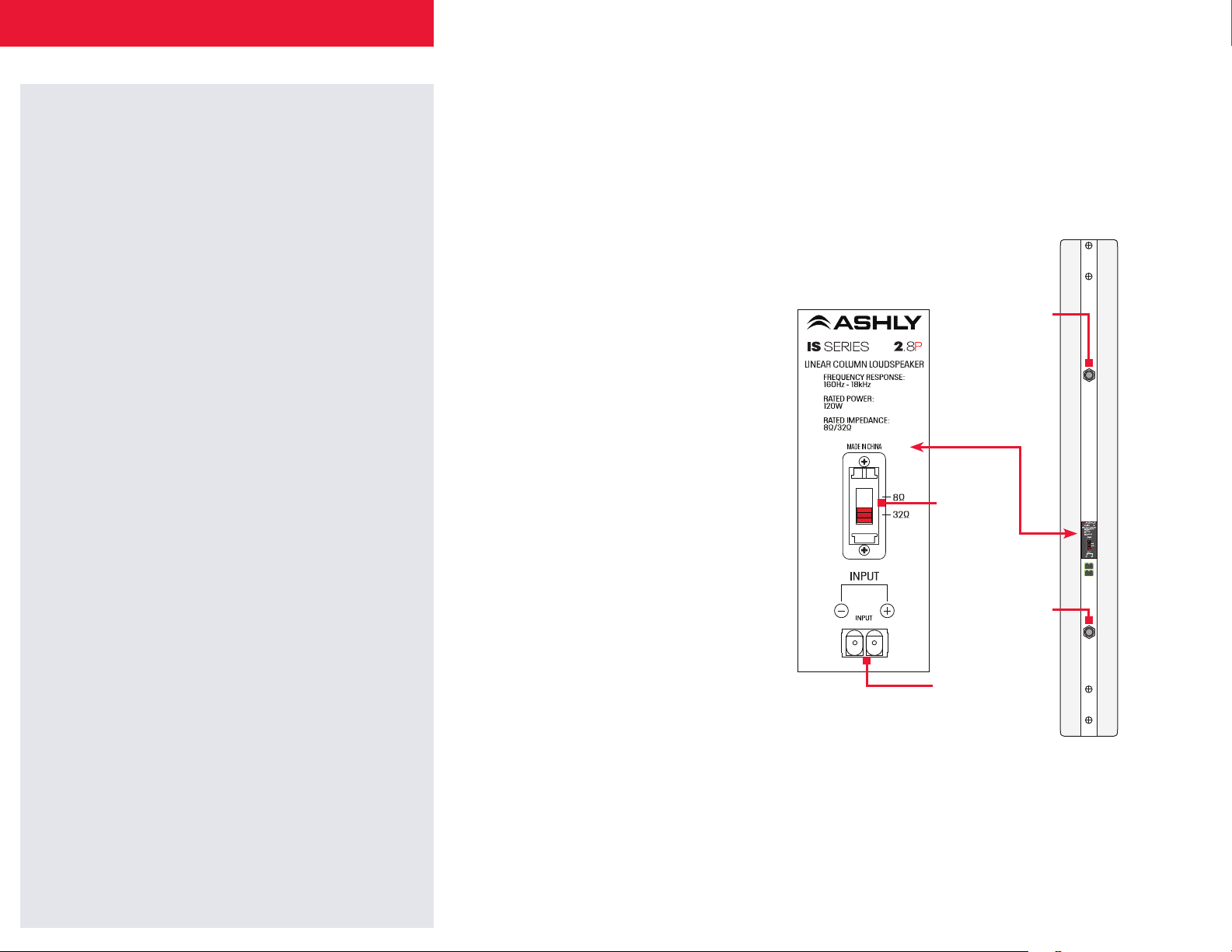
Back Panel Connections
IS Series columns are designed for both
permanent and mobile applications. Both
models have Neutrik® connections. The IS
3.8P adds Neutric SpeakOn connectors; the IS
2.8P has ¼-inch TS jacks.
IS 2.8P
¼-inch TS jack can be
used as the IS 2.8P
input or a pass-through
to another IS 2.8P
8 Ω / 32 Ω
impedance
switch
¼-inch TS jack can be
used as the IS 2.8P
input or a pass-through
to another IS 2.8P
2-conductor
Euroblock terminal
connector
WARNING: When connecting the IS speaker,
*
do not under any circumstances plug outputs
from different amplifiers or amp channels into
more than one jack (any type on the speaker) at
the same time.
*
*
■ Pole sockets on top and side
■ 10mm bolt holes for use with optional flying hardware
3
Page 4
++– –
+– + –
+– + –
+– + –
+– + –
+ –
+ –
+–
+–
+ –
+ –
Ashly 2-ch. Power Amplifier
Ashly 2-ch. Power Amplifier
Ashly Power Amplifier
8 Ω
Ashly 4-ch. Power Amplifier
2 channels @ 8 Ω, 2 -channels Bridge Mode (sub)
Ashly 2-ch. Power Amplifier
Each channel delivers power @ 4 Ω
8 Ω
8 Ω*
Ashly 2-ch. Power Amplifier
Amp running at 4 Ω per channel
8 Ω
Ashly 4-ch.
Power
Amplifier
8 Ω
32 Ω
+
– –
+– + –
+– + –
+– + –
+– + –
+ –
+ –
+–
+–
+ –
+ –
Ashly 2-ch. Power Amplifier
8 Ω
Ashly 4-ch. Power Amplifier
2 channels @ 8 Ω, 2 -channels Bridge Mode (sub)
8 Ω
8 Ω*
Ashly 2-ch. Power Amplifier
Amp running at 4 Ω per channel
8 Ω
Ashly 4-ch.
Power
Amplifier
8 Ω
IS Series + SP Series Operating Manual
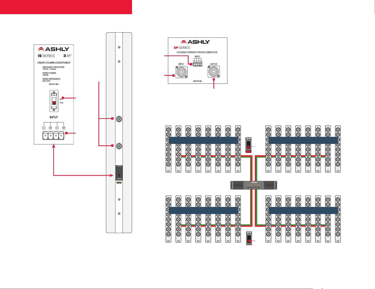
IS 3.8P SP 8.1P/12.1P
Neutrik® SpeakOn
connectors can
be used as the
IS 3.8P input or
a pass-through to
another IS 3.8
8 Ω / 32 Ω
impedance
switch
4-conductor
Euroblock
terminal
connector
WARNING: When
*
connecting the IS
speaker, do not under
any circumstances plug
outputs from different
amplifiers or amp channels
into more than one jack (any
type on the speaker) at the
same time.”.
*
3.8
IS SERIES
LINEAR COLUMN LOUDSPEAKER
FREQUENCY RESPONSE:
100Hz - 20kHz
RATED POWER:
240W
RATED IMPEDANCE:
8Ω/32Ω
MADE IN CHINA
8Ω
32Ω
INPUT
4-conductor
Euroblock
connector
Neutrik® SpeakOn
connector for
input from Power
terminal
Amplifer
Neutrik® for output
to other speakers or
subwoofers.
Eight IS columns • 32 Ω setting @ 62.5 W each Eight IS columns • 32 Ω setting @ 62.5 W each
Eight IS columns • 32 Ω setting @ 62.5 W each Eight IS columns • 32 Ω setting @ 62.5 W each
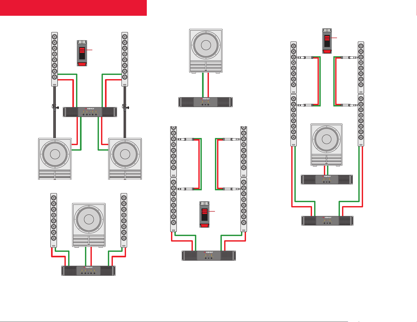
System configurations with
Dual-impedance IS Series
IS Series’ Hi-Z / Lo-Z design allows more
connection options than typical singleimpedance column speakers.
In 8 Ω mode, IS columns are ideal
for typical low-Z and live performance
applications.
However, switching IS columns to 32 Ω lets
one Ashly 4-channel amplifier drive up to 32
individual IS 2.8P or IS 3.8P speakers!
The example below shows 32 IS columns
driven with 62.5 watts each via a 4 x 500watt amplifier.
CA 504 • 4 x 500 W @ 4 ΩAshly 4-channel amplifier
32 Ω
4
Page 5
+– + –
+– + –
+– + –
+– + –
+ –
+ –
+–
+–
+ –
+ –
Ashly 2-ch. Power Amplifier
Ashly Power Amplifier
Bridged Mode
8 Ω
Ashly 4-ch. Power Amplifier
2 channels @ 8 Ω, 2 -channels Bridge Mode (sub)
Ashly 2-ch. Power Amplifier
Each channel delivers power @ 4 Ω
8 Ω
8 Ω*
Each channel delivers power @ 8 Ω
Ashly 2-ch. Power Amplifier
Amp running at 4 Ω per channel
8 Ω
Ashly 4-ch.
Power
Amplifier
+– + –
+– + –
+– + –
+ –
+ –
+–
+–
+ –
+ –
Ashly 2-ch. Power Amplifier
8 Ω
Ashly 4-ch. Power Amplifier
2 channels @ 8 Ω, 2 -channels Bridge Mode (sub)
Ashly 2-ch. Power Amplifier
8 Ω*
Ashly 2-ch. Power Amplifier
Amp running at 4 Ω per channel
8 Ω
Ashly 4-ch.
Power
Amplifier
+
– –
+– + –
+– + –
+– + –
+– + –
+ –
+ –
+–
+–
+ –
+ –
Ashly 2-ch. Power Amplifier
8 Ω
Ashly 4-ch. Power Amplifier
2 channels @ 8 Ω, 2 -channels Bridge Mode (sub)
8 Ω
8 Ω*
Ashly 2-ch. Power Amplifier
Amp running at 4 Ω per channel
8 Ω
Ashly 4-ch.
Power
Amplifier
8 Ω
32 Ω
CA 504 • 4 x 500 W @ 4 ΩAshly 4-channel amplifier
IS Series + SP Series Operating Manual
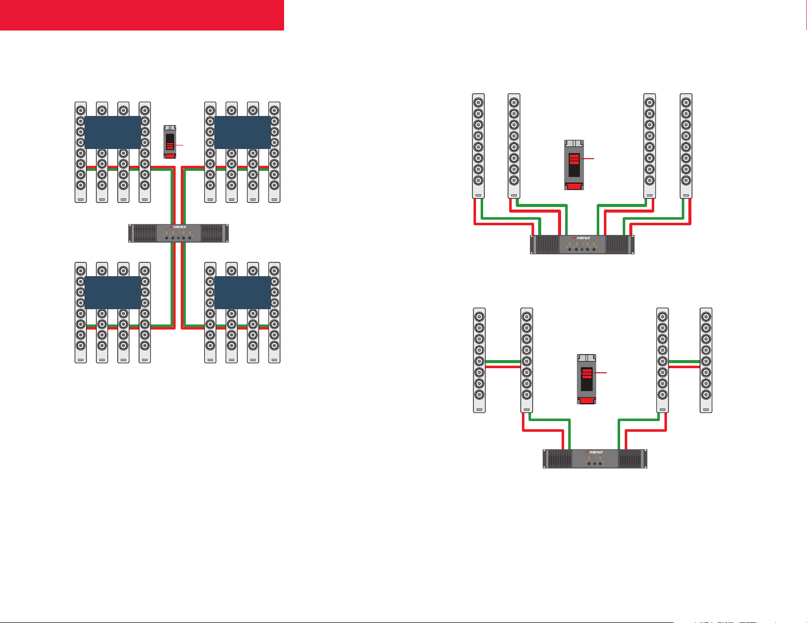
Shown below is a system with 16 IS columns
driven at 62.5 watts each through a 4 x 250-watt
amp.
Four IS columns
32 Ω setting
@ 65.2 W each
4-channel
amplifier
Four IS columns
32 Ω setting
@ 62.5 W each
Four IS columns
32 Ω setting
@ 65.25 W each
CA 504
4 x 250 W
@ 8 Ω
Four IS columns
32 Ω setting
@ 65.2 W each
Other typical configurations
– –
+ +– –
Ashly 4-ch. Power Amplifier
8 Ω
+ +
Wattage for each column =
amplifier power (per channel @ stated
impedance) / total number of columns
For example, 500 W @ 4 Ω = 62.5 W per column.
impedance) / total number of columns.
32 / total number of columns
For example, for 8 IS speakers: 32 / 8 = 4 ohms.
Required amplifier power =
total number of cabinets x desired
If you need 60W per IS Series speaker,
Impedance =
speaker wattage
then 60 x 8 = 480 W
8 Ω
+– + –
5
Page 6
+– + –
+ –
Ashly 4-ch. Power Amplifier
+– + –
+ –
+–
+–
+ –
+ –
Bridged Mode
Ashly 4-ch. Power Amplifier
2 channels @ 8 Ω, 2 -channels Bridge Mode (sub)
8 Ω*
Ashly 4-ch.
Power
Amplifier
+– + –
+ –
Ashly 4-ch. Power Amplifier
2 channels @ 8 Ω, 2 -channels Bridge Mode (sub)
Amp running at 4 Ω per channel
Amp running at 4Ω per channel
IS Series + SP Series Operating Manual
NOTE: If amp
power exceeds
more than 2 x
power handling
of the speaker,
then selecting
32 Ω mode on
the speaker will
draw less from
those amplifier
channels.
Example, CA-
1.04 = 500 W/
ch @
8 Ω (more than
2 x speaker
handling). With
the speaker
set to 32 Ω,
the same amp
operates with
approximately
125 W.
8 Ω*
Ashly 4-ch.
Power
Amplifier
+–
+ –
+–
+ –
8Ω
+ –
Ashly Power Amplifier
+ –
+– + –
Ashly 4-ch. Power Amplifier
8 Ω
+– + –
Ashly 2-ch. Power Amplifier
Ashly 2-ch. Power Amplifier
Bridged Mode
+– + –
Ashly 2-ch. Power Amplifier
6
Page 7

IS Series + SP Series Operating Manual
Ashly AquaControl (via
AquaControl™)
and Protēa™ software presets
for IS Speakers
Audio performance, including directivity and
frequency response of IS Series speakers can
be enhanced when used in conjunction with:
• mXa-1502 mixer amplifier
• Pêma amplifiers
• ne amplifiers (pe version only)
• nXp amplifiers
• ne DSP system and matrix processors
• ne 24.24m DSP matrix processor
• SP series DSP loudspeaker processors
The various capabilities and software used
are shown as follows:
Universal
crossover
Directivity-
weighted,
optimized linear
Ashly
Ashly Product
mXa-1502 AquaControl
Pêma amplifiers Protêa™
ne amplifier
(pe version)
nXp amplifiers Protêa™
ne system and
matrix processors
ne 24.24m DSP
matrix processor
SP series speaker
processors
✤ Basic loudspeaker processing is defined as basic EQ (4-Band PEQ) approximating the appropriate
curve, plus Delay. No advanced EQ or FIR filters.
Software
Protêa™
Protêa™
Protêa™
Protêa™
frequency
response
✔ ✔ ✔
✔ ✔ ✔
✔ ✔ ✔
✔ ✔ ✔
✔ ✔ ✔
✔ ✽
–
implementation
for use between
subwoofers
and full-range
loudspeakers
✽
FIR-corrected,
linear phase
response above
about 300 Hz
–
–
Basic
loudspeaker
processing
N/A
N/A
N/A
N/A
N/A
N/A
✤
✽ HPF/LPF only
7
Page 8
IS Series + SP Series Operating Manual
Frequency [Hz]
On-Axis, Proc essed
On-Axis, No Proc essing
Frequency [Hz]
On-Axis, Proc essed
On-Axis, No Proc essing
Frequency [Hz]
Listening Window, P roces sed
On-Axis, Proc essed
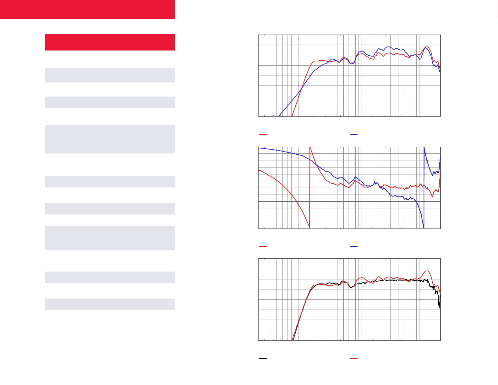
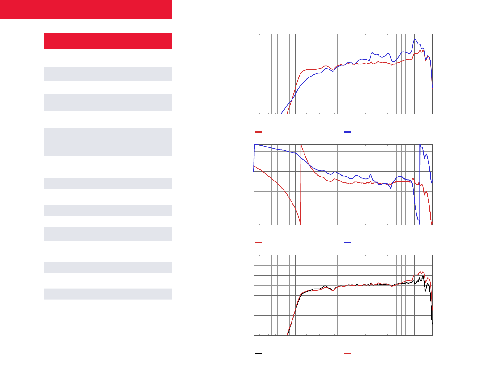
IS 2.8P Specifications
Transducer 8 x 2-inch (51 mm)Neodymium
Frequency Response
(–10dB limits
)1
Sensitivity (ref 2.83V)
Nominal Impedance 8 Ω / 32 Ω switchable
Maximum Continuous SPL, @
a MIV (continuous / peak)
Maximum Continuous SPL,
calculated from power
handling (continuous
1, 2, 3
/peak)
Maximum Input Voltage
1, 2
(MIV)
Power Handling 120 W
Beamwidth
4
Directivity Index (DI) 4 14.4 dB
Directivity Factor (Q) 4 2 7.4
Input Connectors
Mounting Provisions
Enclosure Material Aluminum
Dimensions (HxWxD)
Net Weight 6.4 lbs. / 2.9 kg
Recommended amplifiers
1) With recommended processing (see previous page)
2) Referenced to 1 m
3) The maximum input voltage (MIV) is determined by no more than a 3 dB
change in the frequency response of the loudspeaker system
4) Averaged from 400 Hz to 10 kHz
115 Hz – 20 kHz
1, 2
88 dB
104 dB / 115 dB
1, 2, 3
109 dB / 115 dB
28 dBV, 25.1 V
(equivalent to 80 W
into rated impedance)
Horizontal: 190°
Vertical: 30°
2 x ¼-inch (6.3 mm)
phone jack
1 x 2-position Euroblock
IS-TWM Tilt Wall Mount
IS-FWM Flush Wall Mount
Bracket (included)
24.00 in. x 2.76 in. x 3.54 in.
610 mm x 70 mm x 90 mm
Single-ch.: nXp 400 or higher
Bridged: nXp 150 or higher
Pema 4125, 4250, 8125, 8250
Frequency
Response
(On-Axis)
Phase
Response
(On-Axis)
Frequency
Response
(Listening
Window)
100
95
90
85
80
75
70
Sound pr essure , Leve l [dB]
65
60
20 50 200 500 2k 5k 20k
180
150
120
90
60
30
0
-30
-60
-90
Sound pressure, Phase [deg]
-120
-150
-180
20 50 200 500 2k 5k 20k
100
95
90
85
80
75
70
Sound pr essure , Leve l [dB]
65
60
20 50 200 500 2k 5k 20k
100 1k 10k
100 1k 10k
100 1k 10k
8
Page 9
IS Series + SP Series Operating Manual
Frequency [Hz]
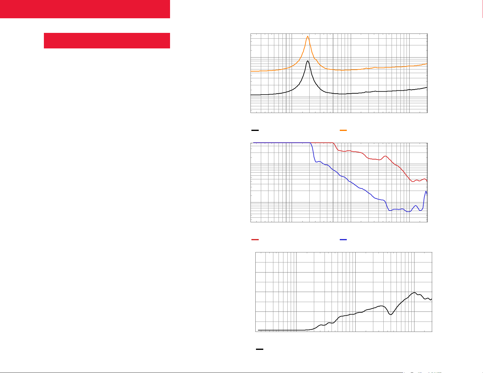
8 ohm
32 ohm
Frequency [Hz]
Horizontal
Ve rtic al
Frequency [Hz]
Direc tivity
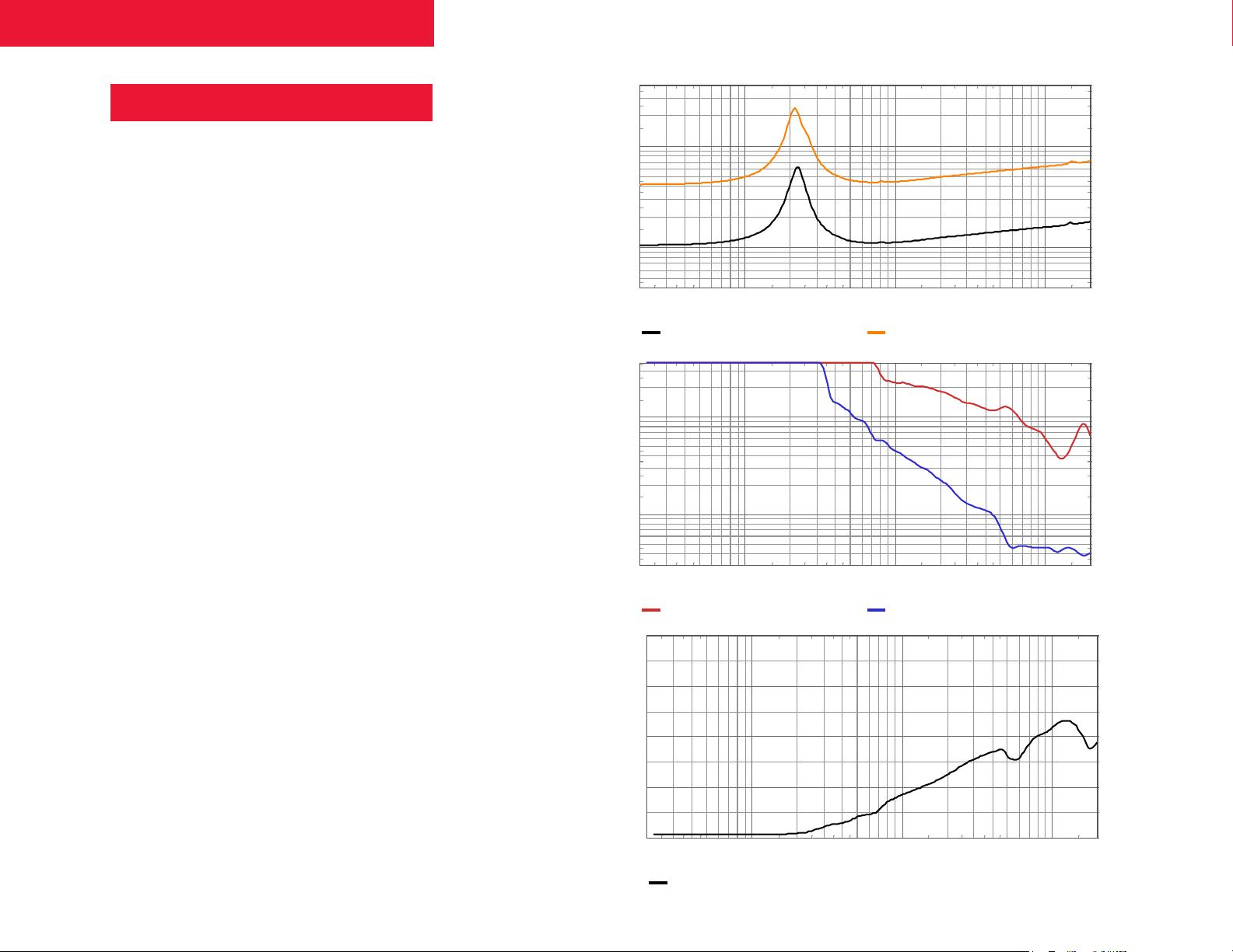
IS 2.8P Specifications
Impedance
Beamwidth
200
100
50
20
10
Imped ance, A mplitude [ohm ]
5
20 50 200 500 2k 5k 20k
200
100
50
100 1k 10k
Directivity
Index
20
Beam width [deg]
10
5
20 50 200 500 2k 5k 20k
40
35
30
25
20
15
Direc tivity Inde x [dB]
10
5
0
20 50 200 500 2k 5k 20k
100 1k 10k
100 1k 10k
9
Page 10
IS Series + SP Series Operating Manual
100 Hz
125 Hz
160 Hz
200 Hz
250 Hz
315 Hz
400 Hz
500 Hz
630 Hz
0∞
800 Hz
1 kHz
1.25 kHz
0∞
1.6 kHz
2 kHz
2.5 kHz
3.15 kHz
4 kHz
5 kHz
6.3 kHz
8 kHz
10 kHz
12.5 kHz
16 kHz
20 kHz
+30∞
0∞
-30∞
+30∞
0∞
-30∞
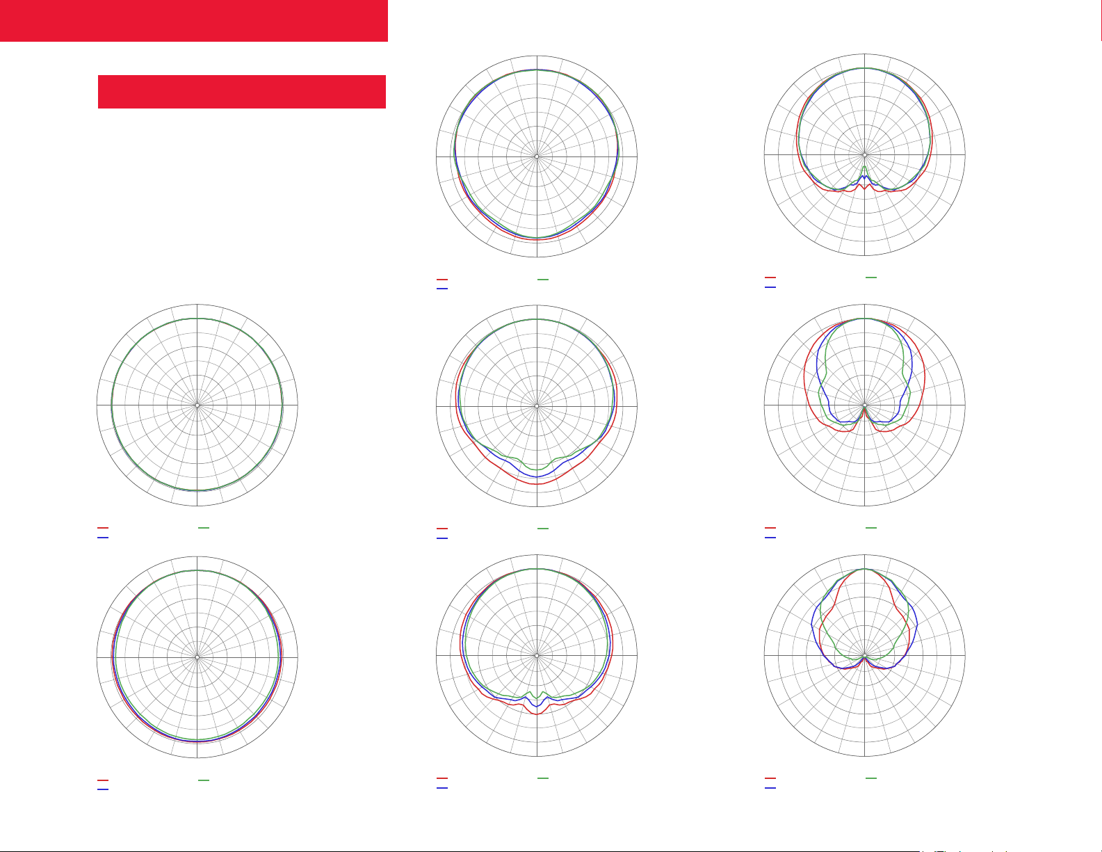
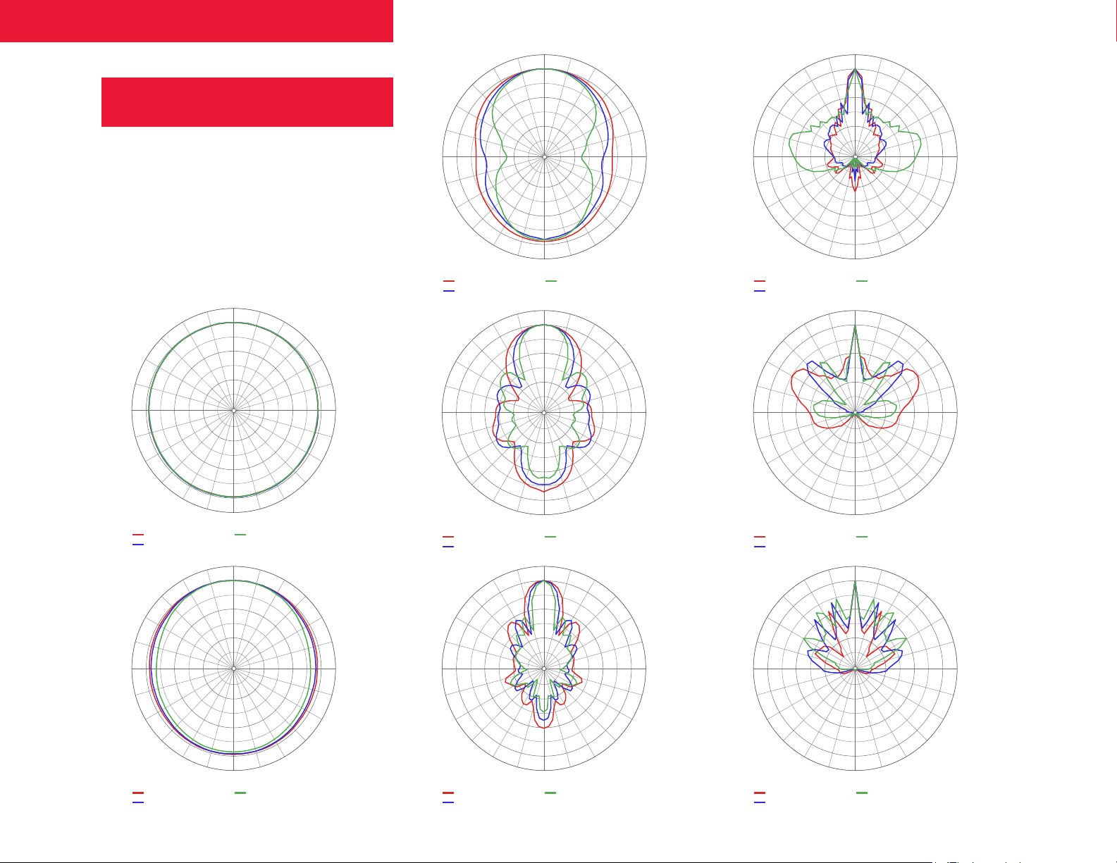
IS 2.8P Specifications
Horizontal & Vertical Polars
(1/3 octave)
Horizontal
0∞
+30∞
+60∞
6 -6 -18 -30
+90∞
0 -12 -24 -36
+120∞
+150∞
+/-180∞
-30∞
-150∞
-60∞
-120∞
+60∞
6 -6 -18 -30
+90∞
0 -12 -24 -36
+120∞
+150∞
+30∞
+60∞
-90∞
6 -6 -18 -30
+90∞
0 -12 -24 -36
+120∞
+150∞
+/-180∞
+/-180∞
-60∞
-90∞
-120∞
-150∞
-30∞
-60∞
-90∞
-120∞
-150∞
+60∞
6 -6 -18 -30
+90∞
0 -12 -24 -36
+120∞
+150∞
+30∞
+60∞
6 -6 -18 -30
+90∞
0 -12 -24 -36
+120∞
+150∞
+/-180∞
0∞
+/-180∞
-60∞
-90∞
-120∞
-150∞
-30∞
-60∞
-90∞
-120∞
-150∞
+30∞
+60∞
6 -6 -18 -30
+90∞
0 -12 -24 -36
+120∞
+150∞
0∞
+/-180∞
-30∞
-150∞
-60∞
-120∞
0∞
+30∞
+60∞
6 -6 -18 -30
-90∞
+90∞
0 -12 -24 -36
+120∞
+150∞
+/-180∞
-30∞
-150∞
-60∞
-120∞
-90∞
+90∞
+30∞
+60∞
6 -6 -18 -30
0 -12 -24 -36
+120∞
+150∞
-30∞
-60∞
-90∞
-120∞
-150∞
+/-180∞
10
Page 11
IS Series + SP Series Operating Manual
100 Hz
125 Hz
160 Hz
200 Hz
250 Hz
315 Hz
400 Hz
500 Hz
630 Hz
800 Hz
1 kHz
1.25 kHz
1.6 kHz
2 kHz
2.5 kHz
3.15 kHz
4 kHz
5 kHz
6.3 kHz
8 kHz
10 kHz
12.5 kHz
16 kHz
20 kHz
+30∞
0∞
-30∞
+30∞
0∞
-30∞
IS 2.8P Specifications
Vertical (1/3 octave)
0∞
+30∞
+60∞
6 -6 -18 -30
+90∞
0 -12 -24 -36
+120∞
+150∞
+/-180∞
-30∞
-150∞
-60∞
-120∞
+60∞
6 -6 -18 -30
+90∞
0 -12 -24 -36
+120∞
+150∞
+30∞
+60∞
-90∞
6 -6 -18 -30
+90∞
0 -12 -24 -36
+120∞
+150∞
+/-180∞
0∞
+/-180∞
-60∞
-90∞
-120∞
-150∞
-30∞
-60∞
-90∞
-120∞
-150∞
+60∞
6 -6 -18 -30
+90∞
0 -12 -24 -36
+120∞
+150∞
+30∞
+60∞
6 -6 -18 -30
+90∞
0 -12 -24 -36
+120∞
+150∞
-60∞
-90∞
-120∞
-150∞
+/-180∞
0∞
-30∞
-60∞
-90∞
-120∞
-150∞
+/-180∞
+30∞
+60∞
6 -6 -18 -30
+90∞
0 -12 -24 -36
+120∞
+150∞
0∞
+/-180∞
-30∞
-150∞
-60∞
-120∞
0∞
+30∞
+60∞
6 -6 -18 -30
-90∞
+90∞
0 -12 -24 -36
+120∞
+150∞
+/-180∞
-30∞
-150∞
-60∞
-120∞
-90∞
+90∞
+30∞
+60∞
6 -6 -18 -30
0 -12 -24 -36
+120∞
+150∞
0∞
-30∞
-60∞
-90∞
-120∞
-150∞
+/-180∞
11
Page 12
IS Series + SP Series Operating Manual
100 1k 10k
110
100
90
80
70
Frequency [Hz]
Sound pr essure , Leve l [dB]
20 50 200 500 2k 5k 20k
105
95
85
75
Listening Window, P roces sed
On-Axis, Proc essed
Frequency [Hz]
On-Axis, Proc essed
On-Axis, No Proc essing
Frequency [Hz]
On-Axis, Proc essed
On-Axis, No Proc essing
110
105
100
95
90
85
80
Sound pr essure , Leve l [dB]
75
70
20 50 200 500 2k 5k 20k
100 1k 10k
IS 3.8P Specifications
1, 2
1, 2, 3
8 x 3-inch (76 mm)
Neodymium
105 Hz – 19 kHz
95 dB
113 dB / 124 dB
Transducer
Frequency Response
(–10dB limits
)1
Sensitivity (ref 2.83V)
Nominal Impedance 8 Ω / 32 Ω switchable
Maximum Continuous SPL, @
a MIV (continuous / peak)
Frequency
Response
(On-Axis)
Maximum Continuous SPL,
calculated from power
handling (continuous /
1, 2, 3
peak)
Maximum Input Voltage
1, 2
(MIV)
Power Handling 240 W
Beamwidth 4
Directivity Index (DI) 4 11.8 dB
Directivity Factor (Q) 4 15.2
Input Connectors
Mounting Provisions
Enclosure Material Aluminum
Dimensions (HxWxD)
Net Weight 12.8 lbs. / 5.8 kg
Recommended amplifiers
1) With recommended processing (see previous page)
2) Referenced to 1 m
3) The maximum input voltage (MIV) is determined by no more than a 3 dB
change in the frequency response of the loudspeaker system
4) Averaged from 400 Hz to 10 kHz
119 dB / 125 dB
30 dBV, 31.6 V
(equivalent to 125 W
into rated impedance)
Horizontal: 170°
Vertical: 25°
2 x NL4 SpeakOn
1 x 4-position Euroblock
IS-TWM Tilt Wall Mount
IS-FWM Flush Wall Mount
Bracket (included)
31.77 in. x 4.06 in. x 5.12 in.
807 mm x 103 mm x 130 mm
Single-channel: nXp 400 or
higher
Bridged: nXp 400 or higher
Pema 4125, 4250, 8125, 8250
Phase
Response
(On-Axis)
Frequency
Response
(Listening
Window)
180
150
120
90
60
30
0
-30
-60
-90
Sound pressure, Phase [deg]
-120
-150
-180
20 50 200 500 2k 5k 20k
100 1k 10k
12
Page 13
IS Series + SP Series Operating Manual
Frequency [Hz]
8 ohm
32 ohm
Frequency [Hz]
Horizontal
Ve rtic al
Frequency [Hz]
Direc tivity Inde x
IS 3.8P Specifications
Impedance
Beamwidth
200
100
50
20
10
Imped ance, A mplitude [ohm ]
5
20 50 200 500 2k 5k 20k
200
100
50
100 1k 10k
Directivity
Index
20
Beam width [deg]
10
5
20 50 200 500 2k 5k 20k
40
35
30
25
20
15
Direc tivity Inde x [dB]
10
5
0
20 50 200 500 2k 5k 20k
100 1k 10k
100 1k 10k
13
Page 14
IS Series + SP Series Operating Manual
100 Hz
125 Hz
160 Hz
200 Hz
250 Hz
315 Hz
400 Hz
500 Hz
360 Hz
800 Hz
1 kHz
1.25 kHz
1.6 kHz
2 kHz
2.5 kHz
3.15 kHz
4 kHz
5 kHz
6.3 kHz
8 kHz
10 kHz
12.5 kHz
16 kHz
20 kHz
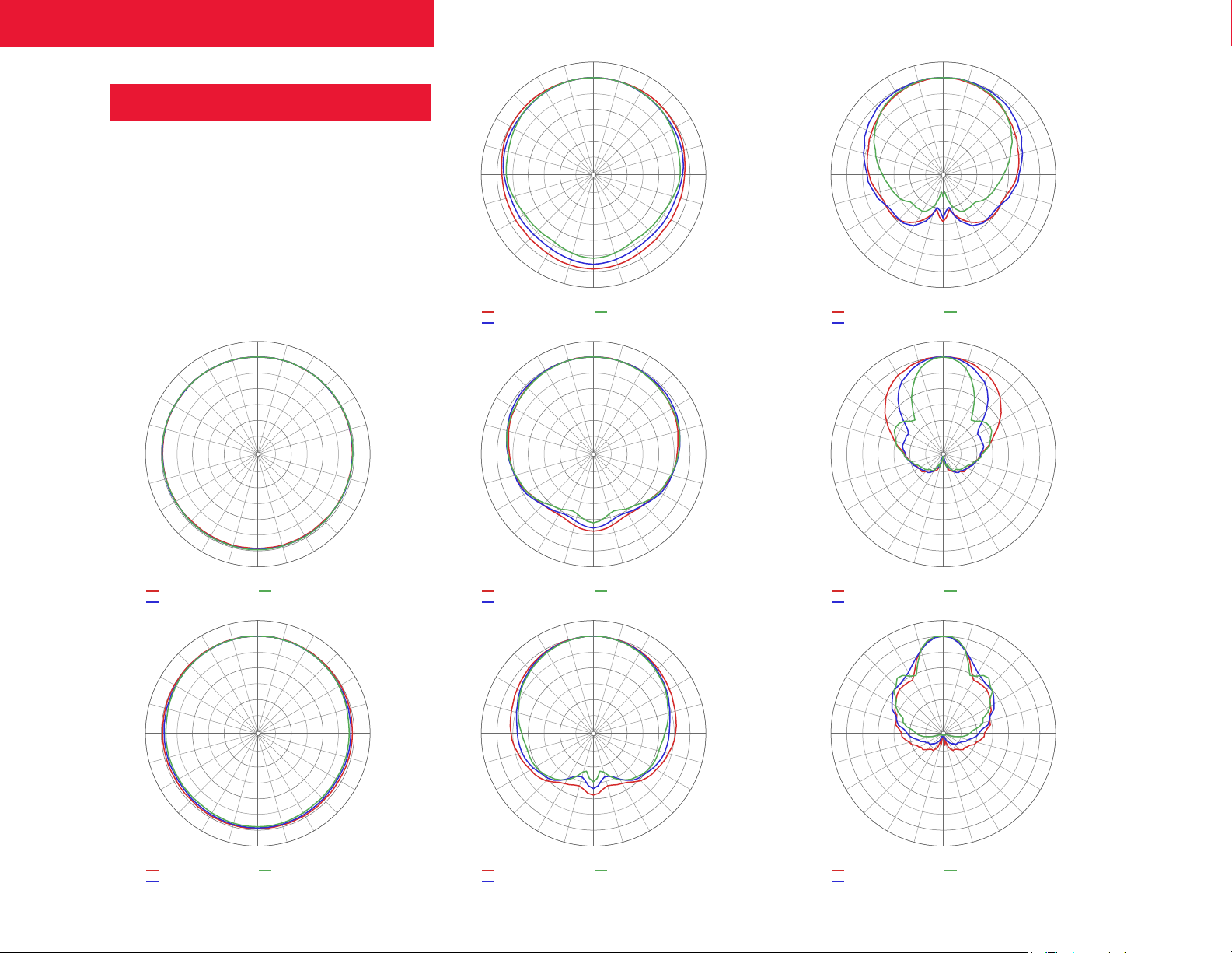
IS 3.8P Specifications
Horizontal & Vertical Polars
(1/3 octave)
Horizontal
0∞
+30∞
+60∞
6 -6 -18 -30
+90∞
0 -12 -24 -36
-30∞
0∞
+30∞
+60∞
6 -6 -18 -30
+90∞
0 -12 -24 -36
+120∞
+150∞
+30∞
-60∞
-90∞
+60∞
6 -6 -18 -30
+90∞
0 -12 -24 -36
+/-180∞
0∞
-30∞
-150∞
-30∞
-60∞
-120∞
-60∞
-90∞
-90∞
+90∞
+90∞
+30∞
+60∞
6 -6 -18 -30
0 -12 -24 -36
+120∞
+150∞
+30∞
+60∞
6 -6 -18 -30
0 -12 -24 -36
0∞
-30∞
-60∞
-90∞
-120∞
-150∞
+/-180∞
0∞
-30∞
-60∞
-90∞
+120∞
+150∞
+30∞
+60∞
6 -6 -18 -30
+90∞
0 -12 -24 -36
+120∞
+150∞
+/-180∞
0∞
+/-180∞
-150∞
-30∞
-150∞
-120∞
-60∞
-120∞
+120∞
+150∞
+30∞
+60∞
6 -6 -18 -30
-90∞
+90∞
0 -12 -24 -36
+120∞
+150∞
+/-180∞
0∞
+/-180∞
-120∞
-150∞
-30∞
-60∞
-90∞
-120∞
-150∞
+120∞
+150∞
+30∞
+60∞
6 -6 -18 -30
+90∞
0 -12 -24 -36
+120∞
+150∞
-120∞
-150∞
+/-180∞
0∞
-30∞
-60∞
-90∞
-120∞
-150∞
+/-180∞
14
Page 15
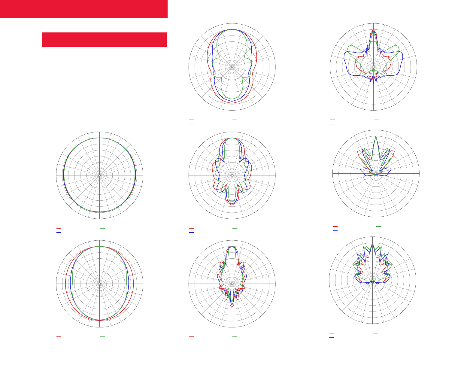
IS Series + SP Series Operating Manual
100 Hz
125 Hz
160 Hz
200 Hz
250 Hz
315 Hz
400 Hz
500 Hz
630 Hz
800 Hz
1 kHz
1.25 kHz
1.6 kHz
2 kHz
2.5 kHz
3.15 kHz
4 kHz
5 kHz
6.3 kHz
8 kHz
10 kHz
12.5 kHz
16 kHz
20 kHz
+30∞
0∞
-30∞
+30∞
0∞
-30∞
IS 3.8P Specifications
Vertical
+60∞
6 -6 -18 -30
+90∞
0 -12 -24 -36
+120∞
+30∞
+150∞
0∞
+/-180∞
-30∞
-150∞
-60∞
-120∞
+60∞
6 -6 -18 -30
+90∞
0 -12 -24 -36
+120∞
+150∞
+30∞
+60∞
6 -6 -18 -30
-90∞
+90∞
0 -12 -24 -36
+120∞
+150∞
+/-180∞
0∞
+/-180∞
-60∞
-90∞
-120∞
-150∞
-30∞
-60∞
-90∞
-120∞
-150∞
+60∞
6 -6 -18 -30
+90∞
0 -12 -24 -36
+120∞
+150∞
+30∞
+60∞
6 -6 -18 -30
+90∞
0 -12 -24 -36
+120∞
+150∞
-60∞
-90∞
-120∞
-150∞
+/-180∞
0∞
-30∞
-60∞
-90∞
-120∞
-150∞
+/-180∞
+30∞
+60∞
6 -6 -18 -30
+90∞
0 -12 -24 -36
+120∞
+150∞
0∞
+/-180∞
-30∞
-150∞
-60∞
-120∞
0∞
+30∞
+60∞
6 -6 -18 -30
-90∞
+90∞
0 -12 -24 -36
+120∞
+150∞
+/-180∞
-30∞
-150∞
-60∞
-120∞
-90∞
+90∞
+30∞
+60∞
6 -6 -18 -30
0 -12 -24 -36
+120∞
+150∞
0∞
-30∞
-60∞
-90∞
-120∞
-150∞
+/-180∞
15
Page 16

IS Series + SP Series Operating Manual
Frequency [Hz]
No Processing
Processed, 110 Hz Crossover
Processed, 150 Hz Crossover
Frequency [Hz]
Impedance
SP 8.1P Specifications
Specifications SP 12.1P
1 x 12-inch (300 mm)
Transducer
Frequency Response
(–10dB limits)
Sensitivity (ref 2.83V)
Nominal
Impedance
Maximum Continuous
SPL, @ MIV (continuous /
peak)
Maximum Continuous
SPL, calculated from
power handling
(continuous / peak)
Maximum Input Voltage
(MIV)
Power Handling
Input Connectors
Enclosure Material
Dimensions (HxWxD)
Net Weight
1
1, 2, 3
1, 2
1 x 8-inch (200 mm)
Ferrite woofer
Ferrite woofer
39 Hz – 180 Hz
43 Hz – 180 Hz
1, 2
99 dB
95 dB
8 Ω
8 Ω
120 dB / 128 dB
110 dB / 116 dB
124 dB / 130 dB
116 dB / 122 dB
1, 2, 3
32 dBV, 31.6 V
(equivalent to 200 W
30 dBV, 24 V (eq to 100 W ...)
into rated impedance)
350 W
150 W
2 x NL4 SpeakOn®
2 x NL4 SpeakOn®
1 x 4-position Euroblock
1 x 4-position Euroblock
Birch Plywood
Birch Plywood
13.25” H x 12” W x 15.63” D/
17.8" H x 14.8" W x 18.85"D/ 452mm H x 376mm
336.55 mm H x 304.8 mm W
W x 479mm D
x 397
39.5 lbs / 18 kg
25.9 lbs / 13.38 kg
SP 8.1P
Frequency
Response
(On-Axis)
Impedance
110
105
100
95
90
85
80
Sound pressure, Level [dB]
75
70
20 50 200 500 2k 5k 20k
200
100
50
20
10
Imped ance, A mplitude [ohm ]
5
10 100 1k 10k
FPO
100 1k 10k
FPO
20 50 200 500 2k 5k
1) With recommended processing (see previous page)
2) Referenced to 1 m
3) The maximum input voltage (MIV) is determined by no more than
mXa-1502
nXp-1502
Single-channel: nXp 400 or higher
Recommended
amplifiers
a 3 dB change in the response of the loudspeaker system
FA-125.2/4 (power-sharing)
Bridged: nXp 400 or higher
FA-250.4 (single -channel)
Pema 4125, 4250, 8125, 8250
Pema 4125/8125 (bridged)
nep/pema 4250/8250
CA-502/4
16
Page 17
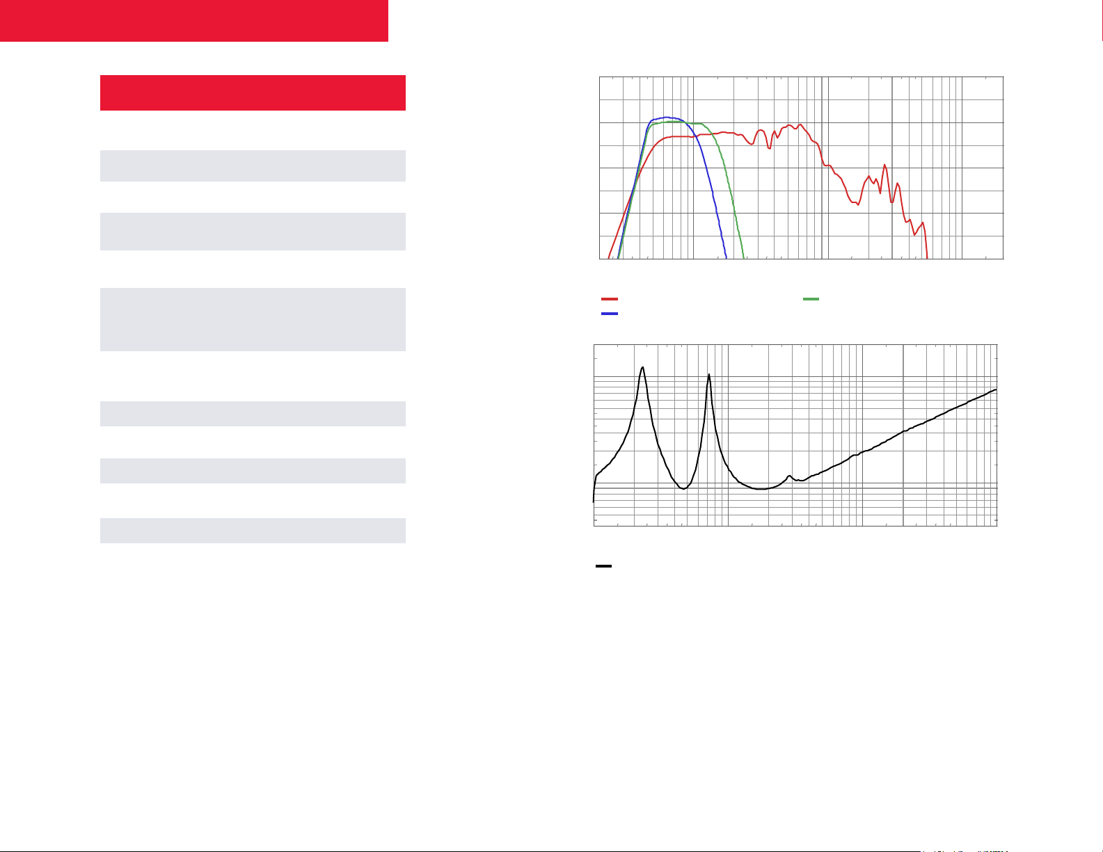
IS Series + SP Series Operating Manual
Frequency [Hz]
No Processing
Processed, 110 Hz Crossover
Processed, 150 Hz Crossover
Frequency [Hz]
Impedance
SP 12.1P Specifications
Transducer
Frequency Response
(–10dB limits)
1
Sensitivity (ref 2.83V)
Nominal Impedance 8 Ω
Maximum Continuous SPL, @
a MIV (continuous / peak)
Maximum Continuous SPL,
calculated from power
handling (continuous /
1, 2, 3
peak)
Maximum Input Voltage
1, 2
(MIV)
Power Handling 350 W
Input Connectors
Enclosure Material Birch Plywood
Dimensions (HxWxD)
Net Weight 39.5 lbs / 18 kg
1 x 12-inch (300 mm)
Ferrite woofer
39 Hz – 180 Hz
1, 2
99 dB
120 dB / 128 dB
1, 2, 3
124 dB / 130 dB
32 dBV, 31.6 V
(equivalent to 200 W
into rated impedance)
2 x NL4 SpeakOn
1 x 4-position Euroblock
17.8" H x 14.8" W x 18.85" D/ 452
mm H x 376 mm W x 479 mm D
Frequency
Response
(On-Axis)
Impedance
110
105
100
95
90
85
80
Sound pressure, Level [dB]
75
70
20 50 200 500 2k 5k 20k
200
100
50
20
10
Imped ance, A mplitude [ohm ]
5
10 100 1k 10k
20 50 200 500 2k 5k
100 1k 10k
Recommended amplifiers
1) With recommended processing (see previous page)
2) Referenced to 1 m
3) The maximum input voltage (MIV) is determined by no more than a 3 dB change in the
nXp4002/4004
nep/pema 4250/8250 (bridged)
KLR-2000
CA-1.02/4
frequency response of the loudspeaker system
17
Page 18
IS Series + SP Series Operating Manual
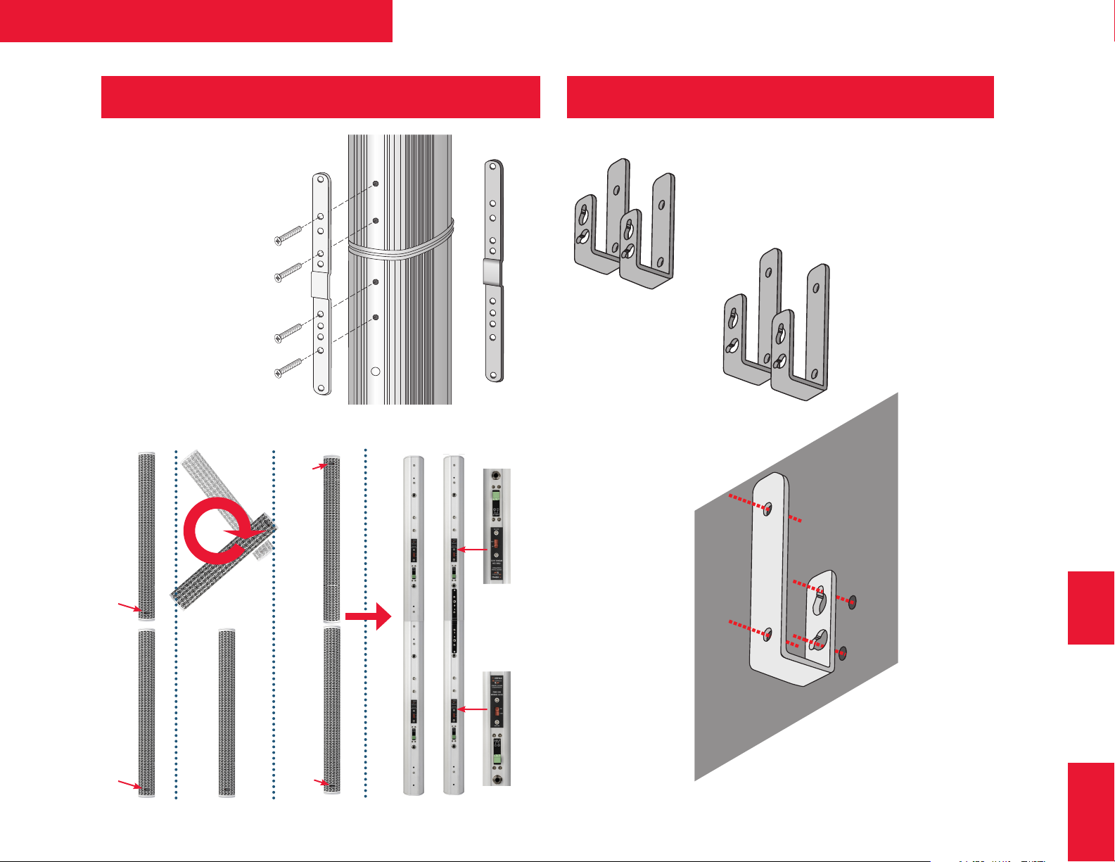
IS-JP2 Joining Bracket Install IS-FW Joining Bracket Install
NOTE: When joining two IS
speakers invert the upper
speaker as shown below.
2 31 3
face
plate
Easy peasy. Use correct fasteners for
Easy peasy. Use correct fasteners for
Easy peasy. Use correct fasteners for
the wall type. Align to a wall stud when
the wall type. Align to a wall stud when
the wall type. Align to a wall stud when
possible.
possible.
possible.
Be sure to securely attach the safety cable.
And remember
to set the
Impedance switch
before mounting.
face
plate
face
plate
face
IS-FWMIS-JP2
plate
18
Page 19
IS Series + SP Series Operating Manual
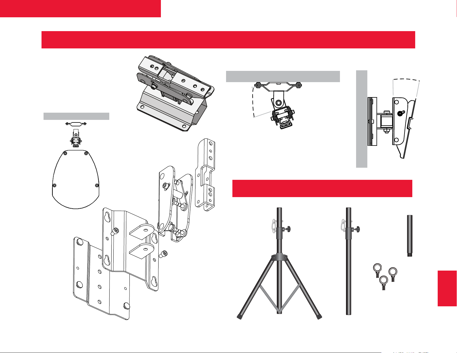
IS-TWM Tilt Bracket Install
NOTE: Use correct fasteners for
the wall type. Align to a wall stud
when possible.
15˚ tilt
And remember to securely
attach the safety cable.
90˚
swivel
Other IS Accessories
IS-TP7B Tripod
for IS 2.8 & IS 3.8
IS-PM6B
Pole Mount
for IS 2.8 &
IS 3.8
IS-PM1B
Pole Mount
for SP Subs
M10-SP
Eyebolts
IS-TWM
19
Page 20
Ashly Audio Inc.
847 Holt Road, Webster, NY USA
US toll-free +1.585.872.0010
Fax +1.585.872.0739
www.Ashly.com
Questions? Install problems?
We think that Ashly Technical
Support is the best in the pro
audio business. Just call us
(8 AM-5PM Eastern time zone)
or e-mail us.
US toll-free +1.585.872.0010
Support@ Ashly.com
 Loading...