

Page 1
FX SERIES
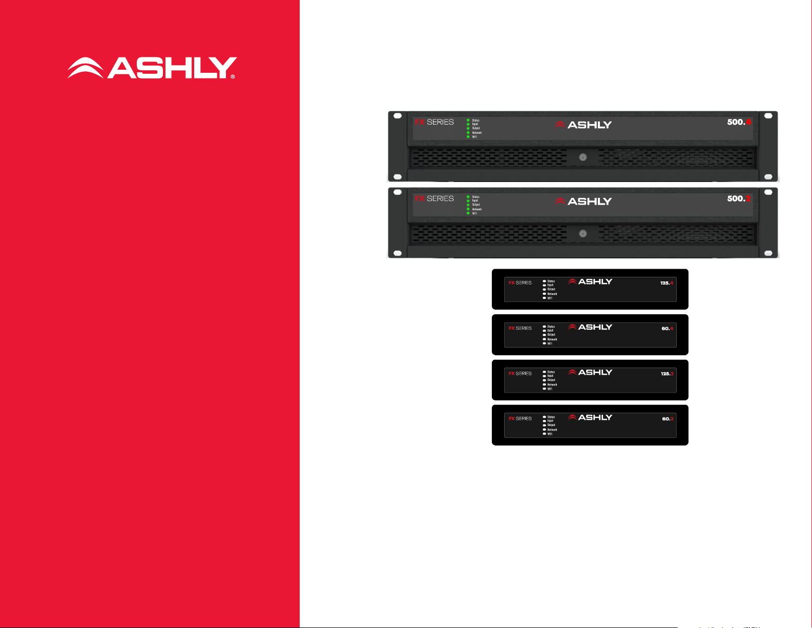
FX-500.4
FX-500.2
FX-125.4
FX-125.2
FX-60.4
FX-60.2
4- and 2-channel
Operating Manual
Power Amplifiers
1
Page 2

FX Amplifier • Operating Manual
FX Amplifier • Operating Manual
Technical and Safety Notices
Please read the following
important technical, safety
and environmental notices
before installing and using your
amplifier.
Technical Notices
All reasonable design and
engineering steps have been taken
to ensure that these amplifiers
always perform satisfactorily in
their intended application and
environment and will provide
appropriate levels of support
to ensure that all reasonable
customer needs and expectations
are met. Such support however
is contingent on the following
provisions.
These amplifiers are Class-I
products and should be installed
with a mains cable including the
required earth connection to
comply with the Safety Class-I.
These amplifiers should always
be installed by competent and
qualified personnel. Amplifier
damage or failure caused by
installation or operational errors
may invalidate support, warranty or
guarantees of performance.
These amplifiers are not suitable
for use in locations where they may
be accessible to minors.
These amplifiers are intended
to be used specifically for the
amplification of audio signals
and for connection to movingcoil loudspeaker systems. Use of
these amplifiers for amplification
of signals outside the audio
band (20Hz to 20kHz) or to drive
transducers other than movingcoil loudspeakers may invalidate
support, warranty or guarantees of
performance.
These amplifiers should only
be used within professionally
installed and configured audio
systems comprising input and
output ancillary equipments that
is known to be of an appropriate
level of performance and in good
operating condition. Any damage
to, or unsatisfactory performance
from, these amplifiers caused
by inadequate or failed input or
output ancillaries may invalidate
support, warranty or guarantees of
performance.
These amplifiers are intended to be
installed and operated indoor in a
controlled environment (pollution
degree, PD2) within an ambient
temperature range of 0°C to 40°C.
These amplifiers are not intended
for use above 2000 meters above
sea level. Amplifiers installation
or operated in environments
outside these limits may invalidate
support, warranty or guarantees of
performance.
Specific warranty terms are the
responsibility of the amplifier reseller.
Safety and Environmental
Notices
Note: The intent of the lightning
flash with arrowhead symbol
in a triangle is to alert the user
to the presence of uninsulated
“dangerous” voltage within the
product’s enclosure that may be of
sufficient magnitude to constitute
a risk of electric shock to humans.
Note: The intent of the exclamation
point within an equilateral triangle
is to alert the user to the presence
of important safety, and operating
and maintenance instructions in
this manual.
WARNING! TO PREVENT FIRE
OR ELECTRIC SHOCK, DO NOT
EXPOSE THIS EQUIPMENT TO RAIN
OR MOISTURE.
Ambient Temperature Note:
If this equipment is operated
in a confined or multiple rack
installation, the internal ambient
operating temperature may exceed
the external ambient temperature.
It is important to ensure in these
circumstances that the published
maximum operating temperature
for the equipment is not exceeded.
Reduced Air Flow: Ensure that rack
or other closed installation does not
restrict the cooling airflow required
for safe and reliable operation of
the equipment.
2
2
Page 3

FX Amplifier • Operating Manual
FX Amplifier • Operating Manual
Important Safety Instructions and Environmental Statement
Read these instructions.
Keep these instructions.
Heed all warnings.
Follow all instructions.
Do not use this apparatus near
water.
Do not submerge the equipment in
water or liquids.
Do not use any aerosol spray,
cleaner, disinfectant or fumigant
on, near or into the equipment.
Clean only with a dry cloth.
Do not block any ventilation
opening. Install in accordance with
the manufacturer’s instructions.
Do not install near any heat sources
such as radiators, heat registers,
stoves, or other apparatus
(including amplifiers) that produce
heat.
To reduce the risk of electrical
shock, the power cord shall be
connected to a mains socket
outlet with a protective earthing
connection.
Do not defeat the safety purpose
of the polarized or grounding type
plug. A polarized plug has two
blades with one wider than the
other. A grounding type plug has
two blades and a third grounding
prong. The wide blade or the third
prong are provided for your safety.
If the provided plug does not fit into
your outlet, consult an electrician
for replacement of the obsolete
outlet.
Protect the power cord from being
walked on or pinched particularly
at plugs, convenience receptacles,
and the point where they exit from
the apparatus.
Do not unplug the unit by pulling on
the cord, use the plug.
Only use attachments/accessories
specified by the manufacturer.
Unplug this apparatus during
lightning storms or when unused
for long periods of time.
Refer all servicing to qualified
service personnel. Servicing is
required when the apparatus has
been damaged in any way, such
as power supply cord or plug is
damaged, liquid has been spilled
or objects have fallen into the
apparatus, the apparatus has been
exposed to rain or moisture, does
not operate normally, or has been
dropped.
The appliance coupler, or the
AC Mains plug, is the AC mains
disconnect device and shall remain
readily accessible after installation.
Adhere to all applicable, local
codes.
Consult a licensed, professional
engineer when any doubt or
questions arise regarding a
physical equipment installation.
Environmental Statement
This product complies with
international directives, including
but not limited to the Restriction
of Hazardous Substances (RoHS)
in electrical and electronic
equipment, the Registration,
Evaluation, Authorization and
restriction of Chemicals (REACH)
and the disposal of Waste Electrical
and Electronic Equipment (WEEE).
Consult your local waste disposal
authority for guidance on how
properly to recycle or dispose of
this product.
3
3
Page 4

FX Amplifier • Operating Manual
FCC Compliance
This device complies with part 15 of the FCC
Rules. Operation is subject to the following two
conditions:
This device may not cause harmful interference
This device must accept any interference
received, including interference that may
cause undesired operation
Note: This equipment has been tested and
found to comply with the limits for a Class
B digital device, pursuant to part 15 of
the FCC Rules. These limits are designed
to provide reasonable protection against
harmful interference in both a commercial
and residential installation. This equipment
generates, uses and can radiate radio
frequency energy and, if not installed and
used in accordance with the instructions,
may cause harmful interference to radio
communications. However, there is no
guarantee that interference will not occur
in a particular installation. If this equipment
does cause harmful interference to radio or
television reception, which can be determined
by turning the equipment off and on, the user
is encouraged to try to correct the interference
by one or more of the following measures:
Unpacking
As a part of our system of quality control,
every Ashly product is carefully inspected
before leaving the factory to ensure flawless
appearance.
After unpacking, please inspect for any
physical damage. Save the shipping carton
and all packing materials, as they were
carefully designed to reduce to a minimum the
possibility of transportation damage should the
unit again require packing and shipping. In the
event that damage has occurred, immediately
notify your dealer so that a written claim to
cover the damages can be initiated.
The right to any claim against a public
carrier can be forfeited if the carrier is not
notified promptly and if the shipping carton
and packing materials are not available for
inspection by the carrier. Save all packing
materials until the claim has been settled.
About Ashly
Ashly Audio was founded in 1974 by a group
of recording engineers, concert sound
professionals, and electronics designers. The
first products were elaborate custom consoles
for friends and associates, but business quickly
spread to new clients and the business grew.
The philosophy we established from the very
beginning holds true today: to offer only the
highest quality audio tools at an affordable cost
to the professional user − ensuring reliability
and long life. Years later, Ashly remains
committed to these principles.
Ashly’s exclusive five-year, worry-free warranty
remains one of the most generous policies
available on any commercial- grade product.
The warranty covers every product with the
Ashly brand name, and is offered at no extra
cost to you.
Please read this entire manual to fully
understand the features and capabilities of this
product.
Reorient or relocate the receiving antenna.
Increase the separation between the
equipment and receiver.
Connect the equipment into an outlet on a
circuit different from that to which the receiver
is connected.
Consult the dealer or an experienced radio/TV
technician for help.
4
Page 5
FX Amplifier • Operating Manual
Overview
1. Introduction and Overview
FX IP connected power amplifiers have been
designed to provide configurable, consistent
and reliable high performance audio power
amplification for residential, commercial
and entertainment applications. Please
read this manual fully before installing and
using an amplifier. If you have any questions
regarding amplifier configuration, installation
or operation please contact the appropriate
customer support portal.
Table of Contents
1 - Amplifier Overview
2 - Carton Contents
3 - Installation
4 - AC Mains and Network Configuration
5 - Configuration Menus
6 - Setup and Signal Routing
7 - GPIO Setup and Connections
8 - Input and Speaker Connections
9 - Operation
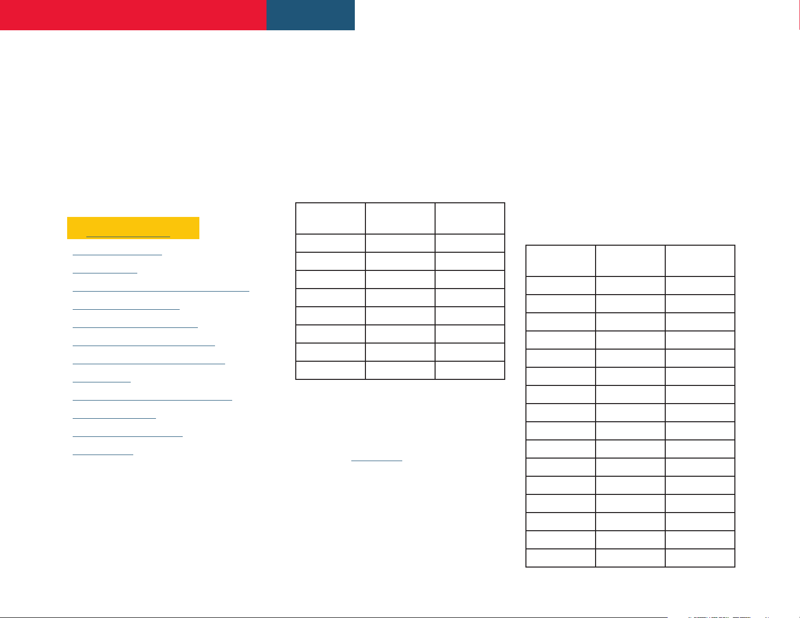
1.1a Full-Rack, FX500 Models
FX 500.4, FX 500.2
FX500 amplifiers can drive conventional low
impedance speakers (Low-Z mode, 2 to 16).
They can also drive 25V transformer coupled
speakers using the Low-Z output. In Hi-Z mode,
the amp can drive 70V or 100V high impedance
transformer coupled loudspeakers. Each model
provides four analog inputs, stereo S/PDIF
digital input & output, and either two or four
outputs (Low-Z mode), or one or two output (HiZ or Lo-Z *BTL mode).
Model &
Mode
FX 500.4
Lo-Z Four 500W
*Lo-Z (BTL) Two 1000W
Hi-Z Two 1000W
FX 500.2
Lo-Z Two 500W
*Lo-Z (BTL) One 1000W
Hi-Z One 1000W
Channels Max Rated
Output/Ch
1.1b Half-Rack, FX125/60 Models
FX 125.4, FX 125.2, FX 60.4, FX 60.2
FX125 and FX60 amplifiers can drive
conventional low impedance speakers (Low-Z
mode, 4 to 16). They can also drive 25V
transformer coupled speakers using the Low-Z
output. In Hi-Z mode, the amp can drive 70V or
100V speakers. Each model provides four analog
inputs, stereo S/PDIF digital input & output, and
either two or four outputs (Low-Z mode), or one
or two output (Hi-Z or Lo-Z *BTL mode).
FX125 and FX60 models
power sharing technology that enables power
to be shared proportionately as required
between the two outputs when in Low-Z mode.
Model &
Mode
FX 125.4
Lo-Z Four 125W
*Lo-Z (BTL) Two 250W
Hi-Z Two 250W
FX 125.2
Lo-Z Two 125W
Channels Max Rated
incorporate automatic
Output/Ch
10 - Signal Flow and Panel Diagrams
11 - Specifications
12 - Rear Panel Drawings
13 - Warranty
*Note: In Lo-Z BTL mode (bridge-tied load),
two amplifier output channels are combined to
create a single, double power output channel.
BTL mode can be engaged via the amplifier
Output Mode configuration setup menu
described in Section 6.3 of this manual.
*Lo-Z (BTL) One 250W
Hi-Z One 250W
FX 60.4
Lo-Z Four 60W
*Lo-Z (BTL) Two 120W
Hi-Z Two 120W
FX 60.2
Lo-Z Two 60W
*Lo-Z (BTL) One 120W
Hi-Z One 120W
5
Page 6
FX Amplifier • Operating Manual
440 mm
17.3 in
332 mm
13.1 in
88 mm
3.5 in
Overview
1.2 Connections
2. Carton Contents
FX amplifier audio input and output
connections are accomplished via Euroblock,
RCA Phono, and RCA S/PDIF connectors. A
GPIO (General Purpose In/Out) Euroblock
connector enables certain amplifier functions
to be controlled remotely. FX amplifiers provide
both their own WiFi hotspot and RJ45 Ethernet
LAN connection for software configuration.
Note: Half-rack FX amplifiers have no mains power
switch and are operational as soon as mains power
is connected via the IEC 60320 mains socket.
1.3 Network Features
FX amplifiers are TCP/IP network connected
devices that require a wireless or wired network
connection to access their configuration
menus. The configuration menus are accessed
FX amplifiers are shipped in a cardboard carton
containing the amplifier unit, a mains cable
appropriate for the sales territory, an accessory
pack, and a document pack. The full contents is
listed below.
- Amplifier unit
- Mains power cable
- Input connector x 2
- GPIO socket connector
- Output connector x 1 or 2
- Adhesive rubber feet x 4
- Document pack
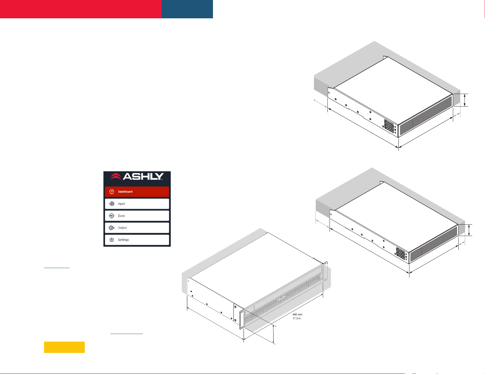
44mm
1.7in
213mm
8.4in
Diagram 1b
220mm
8.7in
25mm
1.0in
FX Half-Rack two channel amplier dimensions.
Shaded area denes ventilation space
via a web page
interface served
up directly by the
amplifier, so there
is no application to
install. The interface
offers access to the
main Dashboard,
plus Input, Zone,
Output, and General
Diagram 1a
FX 2U Full-Rack two & four channel
amplier dimensions. Shaded area
denes ventilation space
80mm
3.1in
Settings.
The configuration menus are fully described in
Section 5.
319mm
12.6in
220mm
8.7in
44mm
1.7in
25mm
1.0in
Diagram 1c
1.4 Dimensions
FX amplifier dimensions and ventilation
FX Half-Rack four channel amplier dimensions.
Shaded area denes ventilation space
requirements are illustrated in Diagrams 1a, 1b,
and 1c. All models are fan-cooled and must be
installed such that ventilation apertures are not
obstructed. Half-rack models can be fitted for fullrack, under-desk, or wall-mounting by purchasing
an optional mounting kit. (see sec. 3.1).
6
Page 7
Connection Plate +
2 x 34 x 6 countersunk
FX Amplifier • Operating Manual
Installation
3. Installation
Note: For half-rack FX models, the rack and
desk/wall mounting components described
and illustrated in Sections 3.1 and 3.2 are not
included with amplifiers, but are available
to purchase as accessories. Contact your
amplifier re-seller for more information.
3.1 FX Mounting
FX 2U full-rack amps include rack-mount ears.
FX half-rack amplifiers are shipped without any
rack-mount hardware. A rack-mount kit can
be purchased separately and configured as
illustrated in Diagram 3a.
The installation and equipment rack should be
configured to provide appropriate ventilation
airflow space around the sides and rear of the
amplifier as illustrated in Diagrams 1a - 1c.
Ventilation airflow space of at least 25 mm (1
in) should be maintained along at least one
side of the amplifier at all times. Ventilation
apertures are also located on the rear panel of
the amplifier and must not be obstructed. It is
important to retain at least 80 mm (3.1 in) free
space for airflow behind the amplifier rear panel.
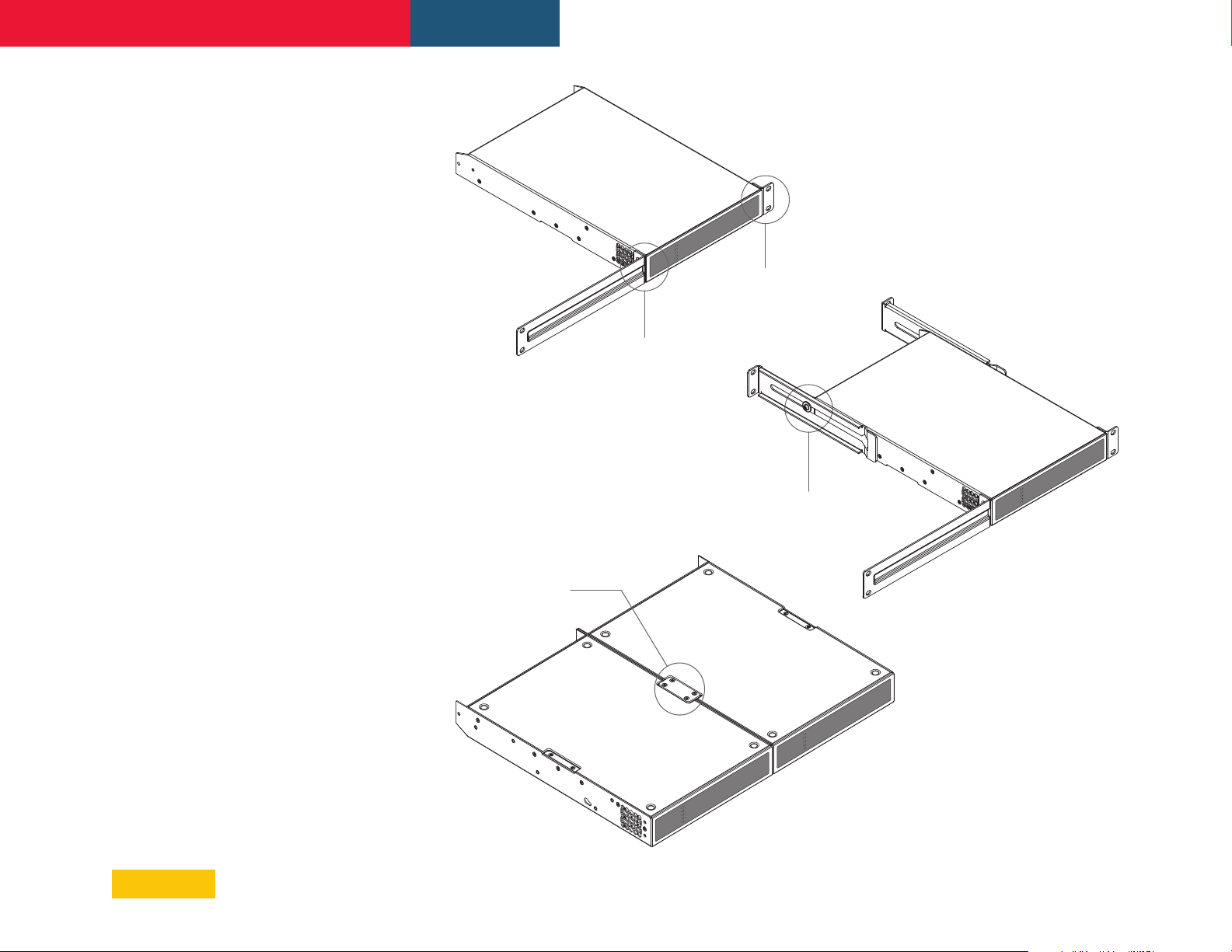
Diagram 3a
Ashly Rack-Mount Kit, *FA1.2RM
FX amplier Rack Ear + Half-rack Extension, for 1 or 2 amps
Half-Rack Extension +
2 x M4 x 8 countersunk
Rack Ear +
2 x M4 x 8
countersunk
Rear Support + Button +
1 x M4 x 8
Diagram 3b
Ashly Rear-Support Kit, *FA2.2RM
FX amplier Rack Support hardware, 2 positions
In addition to rack mount ears, optional rack
mount rear support hardware is available and
can be attached to the amplifier. Rear support
hardware may be appropriate if the amplifier is to
be used in a mobile rack or potentially be subject
to significant movement. Diagram 3b illustrates
the use of rack mount rear support hardware.
Two FX half-rack amplifiers can be
mechanically joined using the connection plate
as illustrated in Diagram 3c. The connection
plate is included with the FA1.2RM kit. Two
small rack ears are included in the same kit for
rack mounting two joined FX amplifiers.
*Half-Rack mounting
kits shown are available
options and are sold
separately.
Diagram 3c
2 x FX ampliers
with Connection Plate, included with FA1.2RM kit
(rack ears not shown)
7
Page 8
FX Amplifier • Operating Manual
Installation
3.2 Free-standing
If not installed in an equipment rack, FX
amplifiers can be placed free-standing on a flat
surface. Adhesive rubber feet are supplied with
all FX models for this purpose.
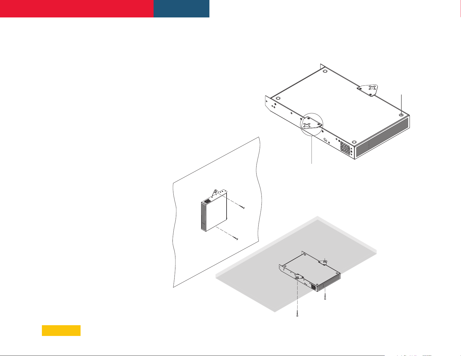
FX half-rack amplifiers can be attached to
the underside of desks or wall mounted using
connecting plate hardware. The adhesive
rubber feet should also be used in these
circumstances to minimize the possibility of
vibration between the amplifier and mounting
surface. Wall and desk mounting is illustrated in
Diagrams 3d and 3e.
It is important in any free standing installation
that airflow through the amplifier’s side panel
mounted fans and rear panel ventilation
apertures is not compromised by adjacent
items. At least 80mm of free space behind the
amplifier and 25mm along at least one side (for
half-rack units)should be retained at all times.
Note: Full-rack models do not have kits for
mounting to a wall or underneath a table,
they can only be used free-standing or rackmounted.
Diagram 3d
Ashly Flush Wall/Table-Mount Kit, *FATWB
FX amplier with desk/wall Mounting Plate and adhesive feet.
2 positions and 4 positions.
Adhesive Foot
4 positions
Mounting Plate +
2 x M3 x 6 countersunk
*Mounting kits shown are
available options and are
sold separately.
Diagram 3e
FX amplier
wall and under-desk mount
8
Page 9

FX Amplifier • Operating Manual
Configuration
4. Configuration
Before making input, output and GPIO
connections, an initial FX amplifier
configuration should be established. It is
particularly important that the output amplifier
format is configured appropriately for the
speakers that are to be connected.
Configuration requires that FX amplifiers
are connected to mains power and network
services. These connections are described in
the following two sections.
4.1 Mains Power Connection
FX amplifiers incorporate a power factor
corrected power supply and can be used with
mains input voltage from 100VAC to 240VAC,
50/60Hz. Use the mains cable supplied with
the amplifier and connect it to a switched
mains supply.
FX half-rack amplifiers have no mains power
switch and are operational as soon as mains
power is connected. Full-rack models have a
front panel power switch.
4.2 Network Services
FX amplifiers are configured via a web page
interface launched from the amplifier using a
TCP/IP Ethernet network connection.
In order to access the web page interface, FX
amplifiers must first connect to the browser
device, or to the network used by the browser
device.
That connection can be made using a wired
LAN (use CAT5, CAT5E, or CAT6 cable), the FX
amplifier's built-in WiFi Access Point (hotspot),
or a local WiFi network (Client Mode).
• Wired LAN (local area network)
A wired LAN connection can be made using
Ethernet cable connected directly to a PC, or to
a PC through an Ethernet switch/router using
CAT5, CAT5E, or CAT6 cable. Note: the FX
amp, PC, and router (if used) must all be on
the same subnet.
Static IP connection:
LAN connection uses a Static IP address, meaning
the browser must connect using a predetermined
fixed IP address. The default IP address for
a wired LAN connection on FX amplifiers is
192.168.64.100. A different Static IP address may
be assigned in the FX LAN configuration page.
Ashly recommends using a Static IP address for
permanent installations. Note: If your network
devices are connected through a router, then
you must log in to the router and set a Static IP
reservation for the FX amplifier.
DHCP connection: The FX amplifier can also
be configured in the Settings>LAN menu to
instead connect using DHCP, meaning the
amplifier receives an IP address automatically
assigned by the router. It is not recommended
to use DHCP for permanent installations, since
the router could potentially change the IP
assignment to the FX at any time.
The front panel Network indicator LED will
illuminate green to indicate the amplifier has
been successfully connected to a wired LAN.
To view the current wired LAN IP address
on a properly connected unit, go to the FX
configuration Dashboard page.
If for some reason you are unable to open the
configuration interface using the wired LAN
connection, use the WiFi Access Point interface
instead, described in the next section. Once
connected using WiFi, wired LAN settings can
be reviewed and configured.
Out of the box, the FX Wired
• WiFi Access Point (hotspot)
Every FX amplifier offers its own dedicated WiFi
access point, or "hotspot", for a direct wireless
connection to a browser device with no outside
network required.
1. With the FX amplifier connected to mains
power, wait for the front panel WiFi indicator
to illuminate green. This indicates the FX
amplifier's Access Point WiFi is available.
2. Using a laptop, tablet, or mobile device, search
for available WiFi networks. Connect to the WiFi
network called "Ashly FX (+ model name + serial
number)". The serial number is found on the rear
panel. Enter the password, "password", which
can be renamed later, then connect.
3.
Once the WiFi Access Point connection
is made, open a web browser and enter
the IP address 192.168.4.1. The amplifier
configuration web page interface will open.
Click on the Settings>Wifi menu for further WiFi
options including enable/disable WiFi, enable/
disable WiFi when connected to LAN, disable WiFi
after 5/10/30 minutes, and reset.
• WiFi Client Mode
To connect and configure the FX amplifier
using a local WiFi network instead of its
dedicated Access Point WiFi, *set the WiFi
mode to "Client" in the Settings>WiFi menu.
Enter the local WiFi network name (SSID) and
password, then click *apply.
*Note: Before changing to WiFi Client Mode, be
sure to first establish a successful wired LAN
connection. Setting WiFi to Client mode disables
access to the FX amplifier's Access Point WiFi.
Having a wired LAN connection assures access
to the amplifier in case something goes wrong
with the local area WiFi connection.
9
Page 10
FX Amplifier • Operating Manual
Configuration
5. Configuration Menus
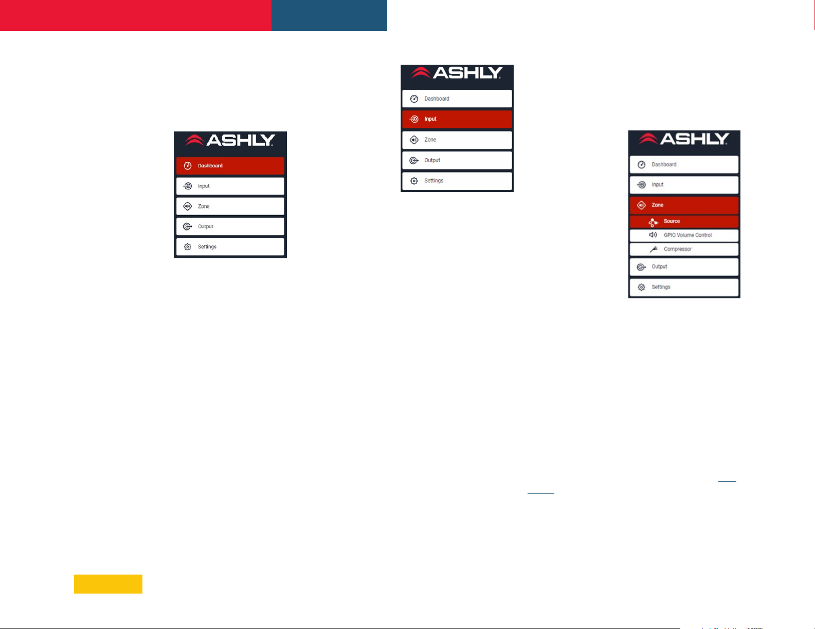
Opening a web browser that is network
connected to a FX amplifier will initially display
five main configuration menu tabs as shown
below:
5.1 Dashboard
The Dashboard tab
is the ‘home’ screen
from which all
other configuration
options can be
accessed.
Within the
Dashboard tab, the
following items are
available for user control or to indicate status.
• Power - Click on the power button to toggle
between ON and Standby. Note: There is no
power switch on FX half-rack models.
• Input Status - Indicates input signal
present
• Output Status - Indicates output signal
present
• LAN - Indicates LAN connection & IP
address
• WiFi - Indicates WiFi connection & IP
address
• Zone Status - Offers control for Mute/
Unmute and Level, and displays an LED
meter indicating signal level for available
zones (zones A-B for 2-channel models,
zones A-D on 4-channel models), and
indicates the currently selected input source
and output routing (speaker channel)for
each zone.
5.2 Input Tab
The Input Tab
provides naming,
mono/stereo
selection, input
sensitivity, and gain
trim for each input
channel, including
the S/PDIF input.
Within the Input tab,
the following items
are available for input configuration.
• Input Name -Enter up to 16 characters
• Mono/Stereo - Define an input as either
mono or stereo.
• Sensitivity - Set this value for the
appropriate input signal level. Settings
include +14dBu and +4dBu (default) for
balanced pro audio signal, -10dBv for HiFi,
and Microphone (50mV / -24dBu / -26dBV).
Note: Only dynamic microphones are
suitable for connection. Phantom power for
condenser microphones is not provided.
• Gain/Trim - Input Gain/Trim is adjustable
±10dB . Gain adjustment is intended to
be used for fine output level adjustment
following initial setup.
• S/PDIF - The S/PDIF input can be set mono
or stereo, with adjustable Gain/Trim of
±10dB
• Pink Noise Generator - The Pink Noise
Generator can be set ON or OFF, with a Gain
range from 0dB to -50dB.
5.3 Zone Tab
The Zone Tab enables installation zones to be
defined and named, and provides access to
three additional sub-menus; Zone Source, Zone
GPIO Volume Control, and Zone Compressor.
Zones might be bar or
restaurant areas for
example, or different
rooms in a home. For
all Zone sub-menus,
the installation zone
under configuration
is selected by
highlighting one of
the zone identifiers
(A, B, C or D) at the
top of the page.
Zone - Source
Within the Zone Source sub-menu, the
following items are available:
• Zone Mute and Level controls
• Zone Mono/Stereo select
• Zone Source - Select as Analog, S/PDIF,
Pink Noise, or Off.
Zone - GPIO Volume Control
The GPIO Volume Control enables an external
potentiometer assembly such as the Ashly
WR-1 to remotely control level of the assigned
zone. The complete GPIO configuration menu
can be found in the Settings>GPIO menu. (see
sec. 7)
Zone - Compressor
The Compressor option allows for default or
custom (manual) signal compression settings
to be applied to the selected zone.
10
Page 11
FX Amplifier • Operating Manual
Configuration
Note: Compression can be useful to reduce
the volume difference between loud and quiet
audio material. The lower the compression
threshold is set, the more the difference
between loud and soft will be reduced. The
overall zone volume may need to be increased
when compression is used. The default
compression parameters are appropriate for
most installations.
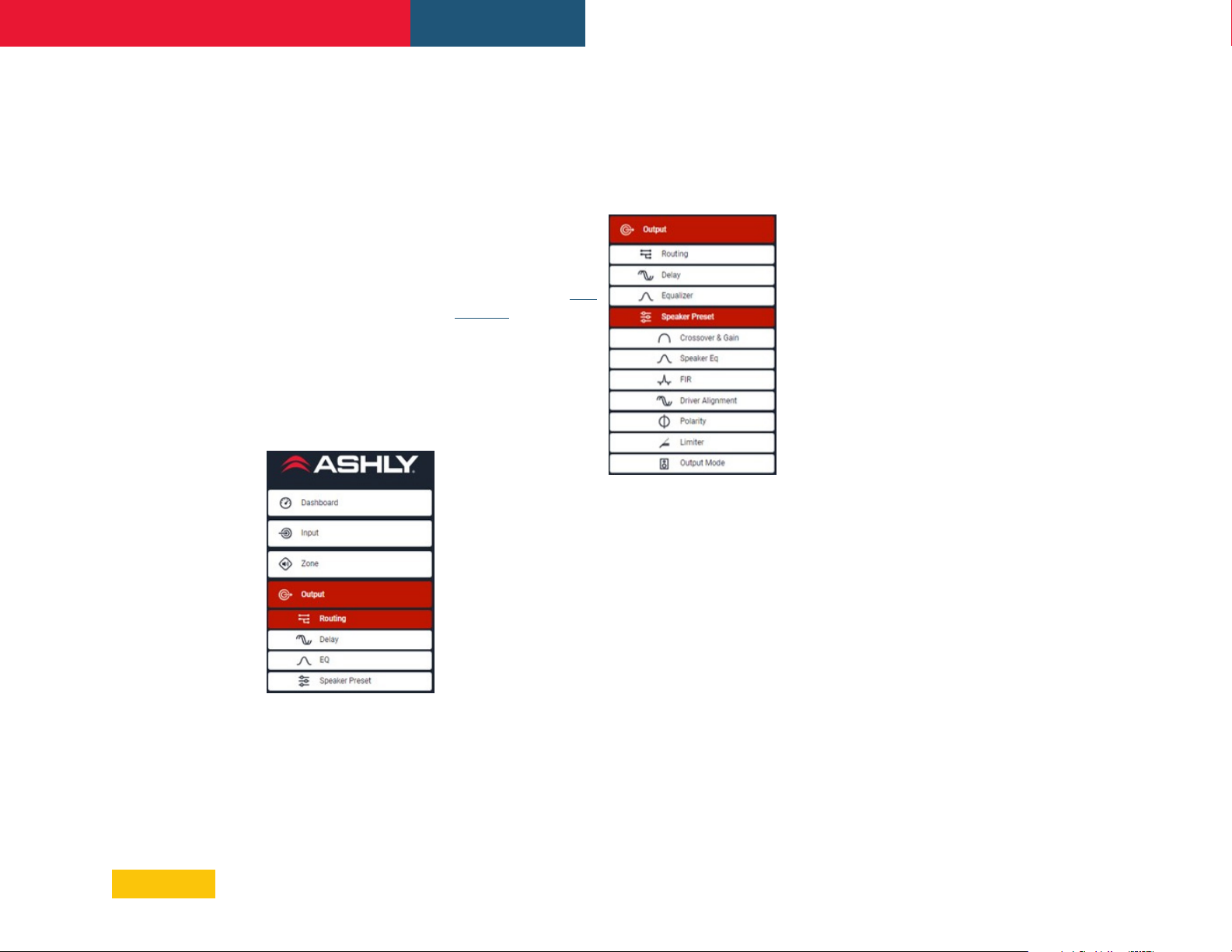
5.4 Output (Speaker) Tab
The Output Tab configures the selected
amplifier speaker output, with additional submenus listed below.
For all Output menus, the amplifier output
(speaker channel) under configuration is
selected by highlighting one of the output
identifiers (1, 2, 3 or 4) at the top of the page.
Note: The number
of individual
outputs available
for configuration
will depend on the
FX amplifier model
and the input, zone
and output mode
configuration.
• Routing menu
assigns the zone
source used for the
selected output.
• Delay menu provides time delay up to
100ms to be applied to the selected output.
• Equalizer menu enables 10-band
parametric equalization to be applied to
the selected output. Equalizer settings
configured for one output can be copied and
applied to another output channel.
5.4a Output Presets
Within the Output tab, a Speaker Preset
sub-menu allows custom configuration of
parameters which can then be exported as
a *.zcp speaker preset file. The *.zcp file is
exported to the same download location used
by your browser.
Created speaker
preset files can
then be added to a
Speaker Library (see
sec. 5.5) for repeated
use later.
The following
parameters can be
individually edited,
saved, and locked
within a speaker
preset file:
• Crossover & Gain
menu enables high or low-pass crossover
filters and gain adjustment to be applied to
individual amplifier outputs. Crossover filter
settings configured for one amplifier output
can be copied and applied to other outputs.
Note: See the specifications section for a list
of all available filter types and slopes.
• Speaker EQ menu enables several types
of equalization to be applied to individual
amplifier outputs following the application
of crossover filtering. Equalizer settings
configured for one amplifier output can be
copied and applied to other outputs. Note:
See the specifications section for a list of all
available filter types.
• FIR menu enables importing of FIR filters up
to 512 taps (coefficients).
• Driver Alignment menu enables time
delay up to 10ms to be applied to individual
amplifier outputs following the application
of crossover filtering.
• Polarity menu enables the polarity of
individual amplifier outputs to be reversed.
• Limiter menu enables Clip, Peak, and
RMS signal limiting to be to be applied to
individual amplifier outputs.
• Output Mode menu enables individual
amplifier outputs to be switched off or
configured for Low-Z or Hi-Z modes.
In either Hi-Z mode, 70V or 100V, a high-pass
filter can be enabled from 20Hz to 200Hz.
Note: Use of a high-pass filter with Hi-Z mode
loudspeakers is useful to avoid the possibility
of distortion caused by low frequency line
transformer saturation. Begin with the
default filter setting of 70Hz. If low frequency
distortion is still audible, increase the
frequency setting one step at a time until the
distortion is no longer audible.
5.4b Speaker Preset files
After all speaker preset parameters have been
configured, click "Export Preset To File" from
the main Speaker Preset page. This creates a
*.zcp file which will be saved to your browser's
download folder. Other options in this menu
include:
Import Preset From File
Select Preset From Library
Clear Preset
11
Page 12
FX Amplifier • Operating Manual
Configuration
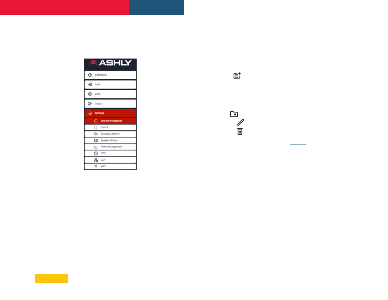
5.5 Settings Tab
The Settings Tab enables miscellaneous
amplifier settings to be configured, installation
site information to be recorded, and provides
access to the following sub-menu items:
• System Information
menu provides
editable text fields
for the recording of
installation data.
• Device menu
displays specific
amplifier information
including model
number, serial
number, firmware
version, MAC
address, and WiFi
MAC address. A
firmware update
routine and device
identifier button are
also found in the
Device menu.
Note: The "Find Me" locator button in the
Device menu will continually flash the
amplifier's front panel LEDs in a unique
pattern until the button is pressed again.
• Speaker Library allows the user to create,
edit, and import custom made or other
provided speaker libraries.
1) Click on the Create button to create a new
speaker library. Name the library and revision
if desired. A library may contain several
speaker series.
2) Select a Speaker Series, then use the
icon to import one or more *.zcp speaker
preset files into that series. Note: *.zcp
speaker preset files can be created and
exported in the Output>Speaker Preset
menu.
3) To add another speaker series, click .
4) To rename a selected speaker series, click
5) To delete a selected preset or series, click .
6) Click the Update button when complete,
the library is now loaded to the amplifier and
can be used in the Output>Speaker Preset
menu for selecting a library preset to an
amplifier speaker output.
7) To export a complete speaker library *.zcl
file, click Export from the Speaker Library
Create or Edit menus. The *.zcl file is exported
to the same download folder that is used by
the browser.
• Power Management menu enables various
automatic standby and switch-on options
to be engaged. A complete description of
each Auto-On mode can be found in the
Settings>Power Management menu.
In addition, the Power Management menu
offers timed Standby and Mute functions.
Important Note: When Audio (Eco) or Trigger
(Eco) Auto-On power management modes
are selected, network communications will
not function when the amplifier is in standby.
• GPIO menu enables configuration of the
multi-purpose GPIO interface pins on the
amplifier rear panel. See section 7 for
complete GPIO configuration details.
• LAN menu enables configuration and
reset of the wired network options and
parameters. See sec 4.2 for details.
• WiFi menu enables configuration of the
wireless network options and parameters.
See sec 4.2 for details.
• Backup & Restore menu enables the
complete amplifier configuration to be
backed up to an external file, and enables
previously saved backup files to be restored
to the currently connected amplifier. Also
found in this menu is a Recovery button
that will restart and reconnect the amplifier.
The Reset button will restore the unit to it's
factory default settings and permanently
erase all data.
8) To import an existing speaker library *.zcl
file, click the Speaker Library Import button.
12
Page 13

FX Amplifier • Operating Manual Configuration
6. Setup and Signal Routing
Thanks to their network based configuration
features, FX amplifiers offer considerable
versatility in terms of sources, signal routing,
installation zones and output modes. Inputs
can be freely assigned to installation zones,
and those zones assigned freely to the
available amplifier outputs in either Low-Z or
Hi-Z modes.
This versatility enables, for example, one
amplifier simultaneously to drive both Low-Z
and Hi-Z speakers, or for different inputs to be
routed to different output zones.
The following paragraphs describe and illustrate
the recommended procedure for configuring
zone and output routing. A general signal flow
schematic is illustrated in section 10.
6.1 Input Setup
1) Open the configuration Dashboard and
select the Input Tab.
2) Select the Input Name field and enter text.
3) Define the input as mono or stereo by
selecting the appropriate option. Defining a
stereo input will reduce the total number of
discrete inputs available.
4) Select an input sensitivity option from the
drop-down menu: +14dB, +4dB, -10dB and
‘microphone’ options are available. Generally,
the +14dB or +4dB options are appropriate
for ‘professional audio’ source hardware with
balanced outputs, while the -10dB option
is more appropriate for ‘consumer audio’
source hardware with unbalanced outputs.
The ‘microphone’ option provides the
significantly greater sensitivity required for
microphones.
Note: Only dynamic microphones are
suitable for connection. Phantom power for
condenser microphones is not provided.
5) If necessary, adjust the input gain using
the slider or up/down icons. Gain adjustment
is intended to be used for fine output level
adjustment following initial use.
6.2 Zone Setup & Routing
1) Open the configuration Dashboard and
select the Zone Tab.
2) Select the zone to be configured. The
number of zones available will depend on
the amplifier model, input setup (mono or
stereo) and output mode (Low-Z or Hi-Z).
For example, a two output amplifier will
have two zones available if only mono inputs
configured, but have only one zone available
if any stereo input is configured. Similarly, a
four output amplifier with only mono inputs
configured but one output configured for Hi-Z
mode will have only three zones available.
Note: When configured in Hi-Z mode, FX
amplifiers operate in ‘bridged’ mode where
the output of two channels is combined. This
means that the number of output channels
available in Hi-Z mode is half that available in
Lo-Z mode.
3) Name the zone by entering text in the
Zone Name field.
4) Adjust the zone volume if required by using
the slider.
5) Define a mono or stereo zone by selecting
the appropriate option. Defining a stereo
zone will reduce the total number of further
zones available.
6) Specify an input source for the zone by
selecting from the drop down source menu.
Note: Selecting a stereo input for a mono
zone will automatically sum the stereo
channels to mono.
7) Set up GPIO Volume Control for each zone
if desired. (see section 7 for details)
8) Set up Compressor for each zone if desired.
6.3 Output Setup
1) Open the configuration Dashboard and
select the Output Tab.
2)
Select the output to be configured. The
number of outputs available will depend on the
amplifier model, zone setup and output mode.
For example, a two output amplifier will have two
outputs available if Low-Z mode is selected but
only one output available if Hi-Z mode is selected.
3) Name the output by typing in the Output
Name field.
Note: Specifying a Zone as stereo will
automatically generate three output channel
source options: left channel, right channel or
summed mono. On a four channel amplifier,
the summed mono signal can potentially be
used to drive a subwoofer, while two other
channels are used for L/R.
4) Select the mode required for the output.
The number of outputs available will depend
on the amplifier model, input setup and zone
setup. For example, a two output amplifier
will have two outputs available if Low-Z mode
is selected but only one output available if
Hi-Z mode is selected.
13
Page 14
FX Amplifier • Operating Manual
Connect Wiper to Pin 4, 5, 6, or7
Potentiometer (>10k Ω)
Ground
+3.3V
5 mm
Configuration
7.
GPIO Setup and Connection
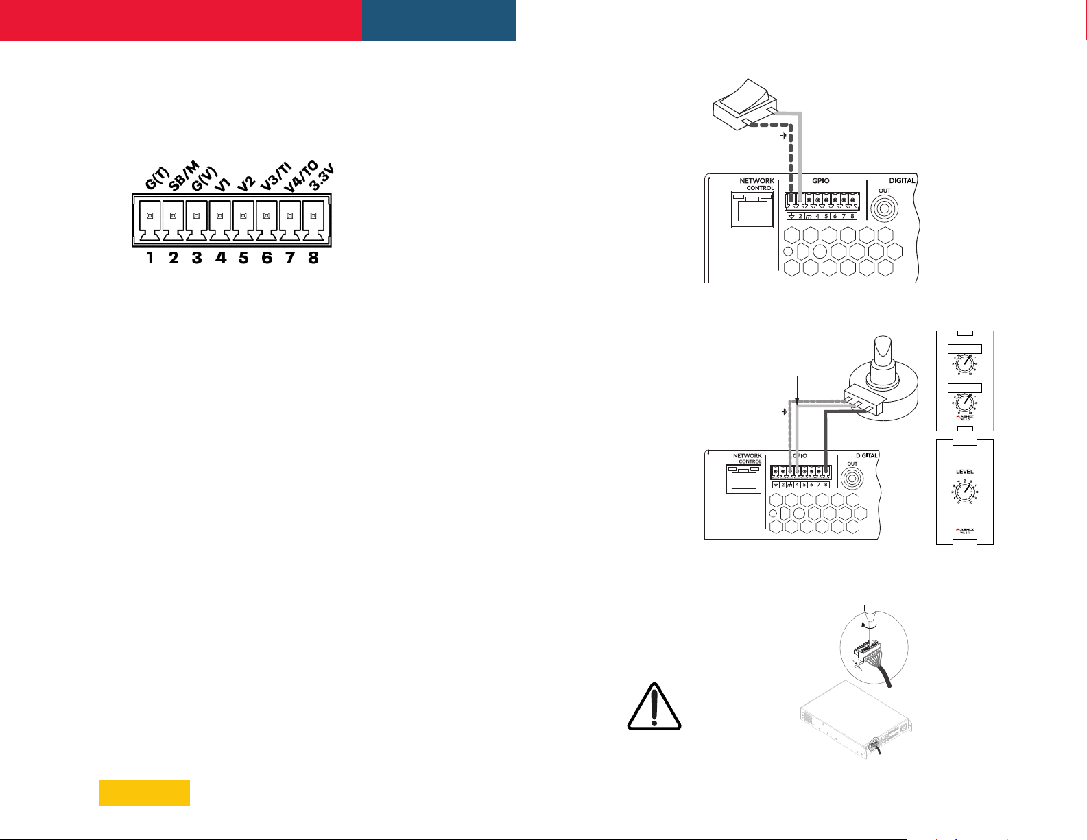
FX amplifiers offer a GPIO Euroblock socket that
enables remote control of volume, standby,
mute and trigger functions. (Diagram 7.3)
Some GPIO pins have multiple functions
depending on their configuration. Each pin
function is described below, as well as in the
Settings>GPIO configuration menu.
• Pin 1, Soft Ground, use only for 12V trigger
and standby/mute input reference.
• Pin 2, Standby or Mute (Diagram 7.1)
Off, Pin 2 has no functionality (default)
Standby (NO) Amplifier will enter Standby
when Pin 2 is connected to Pin 1 GND.
Standby (NC) Amplifier will enter
Standby when Pin 2 is unconnected (floating).
• Pin 5, GPIO Volume Control
(Diagram 7.2)
Off, Pin 5 has no functionality (default)
GPIO Volume Control, When selected, Pin
5 is available for remote volume control input
assignment in Zone>GPIO Volume Control menu.
• Pin 6, Volume Control or 12V Trigger In
Off, Pin 6 has no functionality (default)
GPIO Volume Control, When selected,
Pin 6 is available for remote volume control
input assignment in Zone>GPIO Volume
Control menu.
12V Trigger In, Amplifier will operate when
12V signal is applied to Pin 6, and will enter
Standby when no voltage is applied. Note: This
requires Trigger-Mode to be selected in the
Settings>Power Management menu
(Diagram 7.2)
• Pin7, Volume Control or 12V Trigger Out
Off, Pin 7 has no functionality.
GPIO Volume Control, When selected,
Pin 7 is available for remote volume control
input assignment in Zone>GPIO Volume
Control menu.
(Diagram 7.2)
Switch open or closed
toggles Standby or Mute
depending on options
selected in the GPIO
Settings Menu
Ground
Standby/Mute
Diagram 7.1: GPIO Connections for remote
standby/mute switch
Mute (NO) All amplifier outputs are
muted when Pin 2 is connected to Pin 1 GND.
Mute (NC) All amplifier outputs are
muted when Pin 2 is unconnected (floating).
• Pin 3, Ground, use only as ground reference
for GPIO Volume Control and Trigger Out.
• Pin 4, GPIO Volume Control
(Diagram 7.2)
Off, Pin 4 has no functionality (default)
GPIO Volume Control, When selected, Pin
4 is available for remote volume control input
assignment in Zone>GPIO Volume Control menu.
12V Trigger Out, When selected, Pin
7 provides 12V for use with Trigger Input
function on Pin 6. (default)
• Pin 8, 3.3V power, use for GPIO volume
controls. Note: GPIO Pin 8 has an output
impedance of 1k. Connected devices must
be able to sink 3.3mA.
Note: The GPIO connector must not
be used for any unintended purpose.
Amplifier damage may result from
incorrect use of GPIO pins. Shielded
cable must be used when connecting standby
switches and potentiometers via GPIO pins.
Diagram 7.2: GPIO Potentiometer connections
for remote volume control. Use Ashly WR-1 or
WR-1.1 wall remote or equivalent circuit.
Diagram 7.3: GPIO connections
14
Page 15
FX Amplifier • Operating Manual Connections
5 mm
8. Connections
8.1 Mains Power Connection
FX amplifiers incorporate a power factor
corrected universal power supply and can be
used with mains input voltage from 100VAC
to 240VAC, 50/60Hz. Use the mains cable
supplied with the amplifier.
FX half-rack amplifiers have no mains power
switch and are operational as soon as mains
power is connected. Ensure that all signal,
GPIO and output connections are made before
connecting the amplifier to mains power.
8.2 Input Connections
All FX amplifier models provide four balanced
or unbalanced analog audio inputs and a
stereo S/PDIF digital audio input. Any input
channel can be routed to any zone using the
Zone>Source menu. See Sections 6.2 or 5.3.
Analog Inputs
FX analog inputs are of line level format
with a default input sensitivity of +4dBu (full
output voltage swing/sensitivity) in all output
modes. Input signal levels up to +24dBu can
be handled without input clipping. Input
sensitivity options are set via the amplifier
network interface Input>Sensitivity menu. See
Sections 6.1 or 5.2.
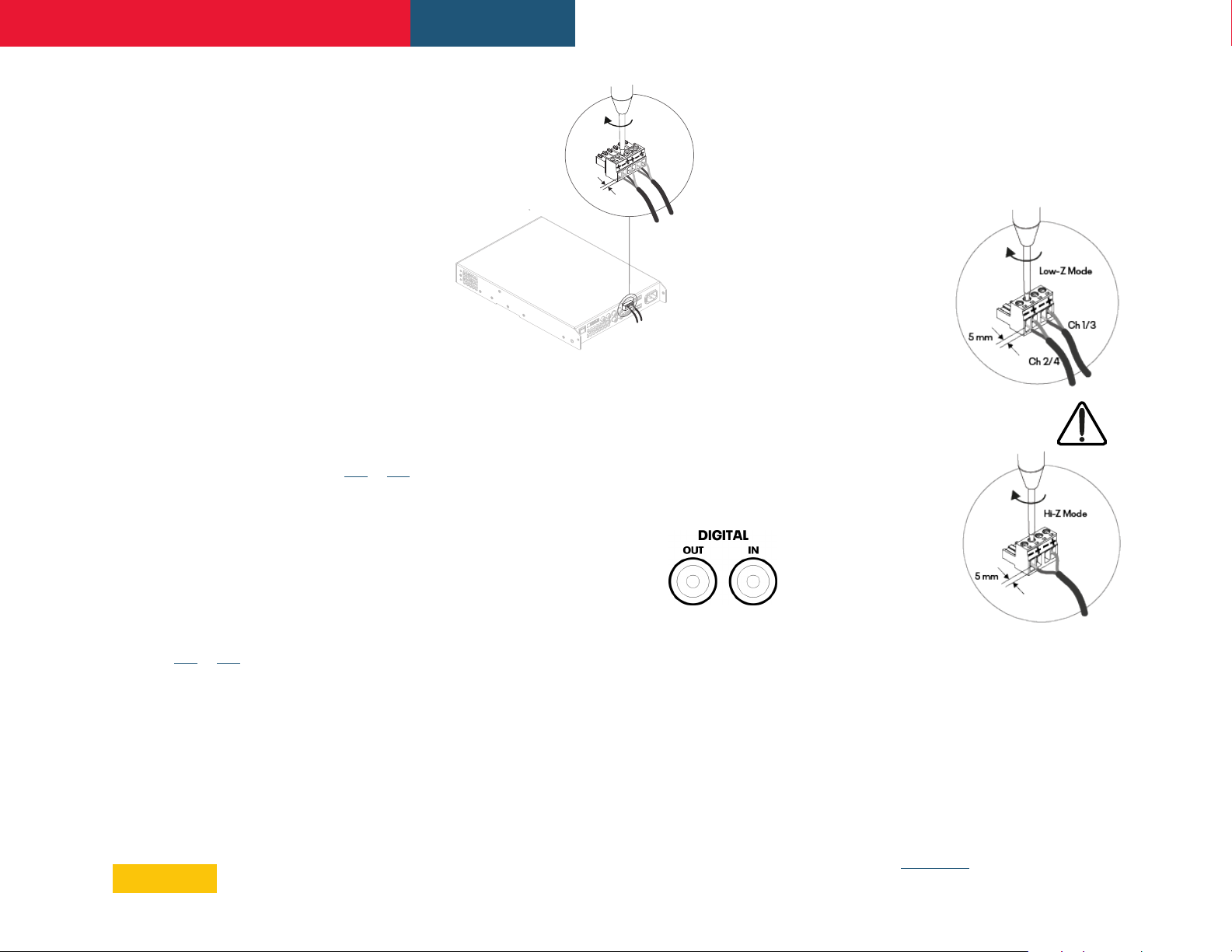
• Balanced input connections to the
amplifiers are made via male ‘Euro Block’
connectors. Connecting cables to the
supplied female input connectors is
illustrated in Diagram 8.2.
• Unbalanced input connections to the
amplifiers are made via RCA phone jacks.
Diagram 8.2: Balanced Input connections
Note: 2 channel amplifier model connections
differ from 4 channel models only in the
deletion of channel 3 and channel 4 output
connectors. Input and GPIO connections
remain the same between all FX models.
Digital Input/Output
FX offers a S/PDIF
stereo digital audio input
connection via a single RCA
Phone jack.
A S/PDIF digital audio output jack is also fitted.
The S/PDIF output signal by default reflects
the input to amplifier installation zones A & B
and is intended to be used for daisy chaining FX
amplifiers.
Note: 75Ω RCA Phono cables specifically
intended for digital audio should always be
used for S/PDIF connections. Standard Phono
cables can be used but may not result in
optimal performance.
8.3 Output Speaker Connections
Output connections from the amplifiers are
achieved via male ‘Euro Block’ connectors.
Ensure that speaker connection polarity is
correct throughout the installation:
• In the case of Low-Z
speaker connections,
positive (+)
amplifier terminals
should always be
connected to positive
speaker terminals
and negative (–)
amplifier terminals
always connected
to negative speaker
terminals.
• In the case of Hi-Z (70V or 100V)
speaker connections,
the two speaker
cable conductors
should be connected
between the positive
(+) terminal of Output
1 and the negative
terminal (-) of Output
2, and likewise for
Outputs 3 and 4.
• Output mode options (Low-Z or Hi-Z)
are configured via the amplifier network
interface in the Output>Speaker
Preset>Output Mode menu.
Note: The exclamation point printed next to the output
terminals of the amplifiers is, in addition to the CLASS
2 WIRING text, intended to alert users to the risk of
hazardous voltages. Output connectors that could
pose a risk are marked with the exclamation point. Do
not touch the output terminals while the amplifier is
switched on. Make all connections with the amplifier
switched off. See Section 8.1 of this manual.
15
Page 16
FX Amplifier • Operating Manual
Connections
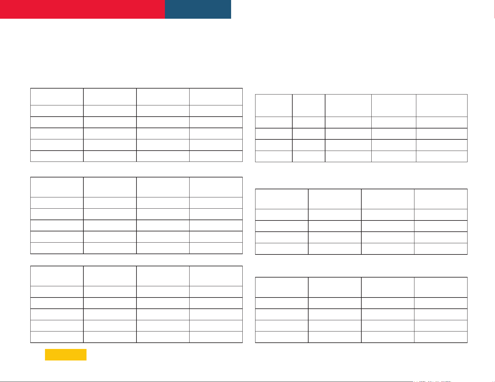
8.4a Speaker Cable Gauge (FX60 & FX125 models)
FX speaker connection cable gauge should be chosen appropriately to reflect
the type of installation. The following tables specify the appropriate cable
gauge for less than 0.5dB cable loss with different installation types and cable
lengths.
FX60 & FX125 Amplier Cable Gauge Table: Low-Z installations. 4Ω & 8Ω loads
Cable Cross Section
(mm2)
0.5 ≈20 2, (7ft) 5, (16ft)
0.8 ≈18 4,(13ft) 8, (26ft)
1.3 ≈16 6, (20ft) 12, (39ft)
2.1 ≈14 9, (30ft) 19, (62ft)
3.3 ≈12 14, (46ft) 30, (98ft)
FX60 & FX125 Cable Gauge Table: 70V Hi-Z installations
Cable Cross Section
(mm2)
0.5 ≈20 84, (276ft) 42, (138ft)
0.8 ≈18 132, (433ft) 66, (217ft)
Cable Gauge
(AWG)
Cable Gauge
(US)
Max Cable Length
in meters (ft), 4Ω load
Max Cable Length
in meters (ft),
125W/channel
Max Cable Length
in meters (ft), 8Ω load
Max Cable Length
in meters (ft),
250W/channel
8.4b Speaker Cable Gauge (FX500 models)
FX speaker connection cable gauge should be chosen appropriately to reflect
the model and type of installation. The following tables specify the appropriate
cable gauge for less than 0.5dB cable loss in Lo-Z mode, and less than 1.0dB
cable loss in Hi-Z modes.
FX500 Amplier Speaker Cable Gauge Table: Low-Z
installations, 0.5dB attenuation, 2Ω, 4Ω ,& 8Ω loads
Cable Cross
Section
(mm2)
0.8 ≈18 N/A 5, (16ft) 10, (33ft)
1.3 ≈16 5, (ft) 10, (33ft) 20, (66ft)
2.1 ≈14 8, (ft) 17, (56ft) 35, (115ft)
3.3 ≈12 14, (ft) 28, (92ft) 55, (180ft)
Cable Gauge
(AWG)
FX500 Amplier Speaker Cable Gauge Table: 70V Hi-Z installations, 1.0dB
attenuation, 20 speakers evenly distributed.
Cable Cross Section
(mm2)
0.8 ≈18 25, (82ft) 20, (66ft)
Max Cable Length
in meters (ft), 2Ω
load
Cable Gauge
(AWG)
Max Cable Length
in meters (ft), 4Ω
load
Max Cable Length
in meters (ft),
1000W (bridged)
Max Cable Length
in meters (ft), 8Ω
load
Max Cable Length
in meters (ft),
1200W (bridged)
1.3 ≈16 210, (689ft) 105, (345ft)
2.1 ≈14 334, (1,096ft) 166, (545ft)
3.3 ≈12 532, (1,745ft) 265, (869ft)
FX60 & FX125 Cable Gauge Table: 100V Hi-Z installations
Cable Cross Section
(mm2)
0.5 ≈20 171, (561ft) 85, (279ft)
0.8 ≈18 269, (883ft) 134, (440ft)
1.3 ≈16 430, (1,411ft) 215, (705)
2.1 ≈14 683, (2,241ft) 341, (1,119ft)
3.3 ≈12 1087, (3,566ft) 542, (1,778ft)
Cable Gauge
(US)
Max Cable Length
in meters (ft),
125W/channel
Max Cable Length
in meters (ft),
250W/channel
1.3 ≈16 50, (164ft) 40, (131ft)
2.1 ≈14 80, (262ft) 60, (197ft)
3.3 ≈12 125, (410ft) 100, (328ft)
FX500 Amplier Speaker Cable Gauge Table: 100V Hi-Z installations, 1.0dB
attenuation, 20 speakers evenly distributed.
Cable Cross Section
(mm2)
0.8 ≈18 50, (164ft) 30, (98ft)
1.3 ≈16 100, (328ft) 60, (197ft)
2.1 ≈14 160, (525ft) 100, (328ft)
3.3 ≈12 250, (820ft) 160, (525ft)
Cable Gauge
(AWG)
Max Cable Length
in meters (ft),
1000W (bridged)
Max Cable Length
in meters (ft),
1500W (bridged)
16
Page 17

FX Amplifier • Operating Manual
Operation
9. Operation
Once all connections have been made and
configuration options selected, FX amplifiers
are ready for use. If an input signal above -60dB
is present on any input, the front panel Input
and Standby indicators will illuminate green to
indicate normal amplifier operation. Audio will
be heard from any connected speakers.
Note: FX amplifiers will not switch on from
Standby Mode unless an input signal is present
or a network or external standby switch is
operated.
Amplifier outputs will mute if no input signal
is present for 5 minutes, and the amplifier will
switch automatically to Standby Mode if no
signal is present on any input for more than 15
minutes. Alternative standby and mute delay
times can selected in the Settings>Power
Management menu. Amplifier cooling fan speed
is temperature controlled. The fan will switch off
when the amplifier enters standby mode.
9.1 Front Panel LEDs
FX amplifier front panel indicators illuminate to
indicate the following operational states:
• Status
Off – Mains power disconnected.
Green – Amplifier operational.
Pulse Green – Standby Mode.
Amber – GPIO triggered Standby Mode
• Input
Off – No input signal present.
Green – Signal present on one or more
inputs.
Amber – Signal limiting/clipping on one or
more inputs.
• Output
Off – No output signal present.
Green – Signal present on one or more
outputs.
Amber – Signal limiting/clipping on one or
more outputs.
Red – One or more channel pair is in
overload/protection mode.
• Network
Off – No Ethernet network detected.
Green – Ethernet network detected.
• WiFi
Off – WiFi disabled.
Green – WiFi enabled.
9.2 Automatic Power Sharing
FX60 and FX125 amplifier models incorporate
a power sharing feature that automatically
shares the total power available from the
amplifier’s internal power supply across
each pair of output channels. If one channel
temporarily demands more than the amplifier’s
continuous power rating while other channel
is demanding less, the excess power available
from the internal power supply is automatically
made available to the over-power channel.
Power sharing optimizes the amplifier’s ability
to deliver maximum power into dynamic
loudspeaker loads when playing music program
material.
Note: On FX500 models, there is no significant
power sharing capability.
9.3 Factory Reset
FX amplifiers can be reset using the following
methods.
• Restart Device, In the configuration
Settings> Backup & Restore menu, there is
a button called Restart Device. Performing a
Device Restart does not erase any presets or
data from the FX amplifier.
• Full Reset, In the configuration Settings>
Backup & Restore menu, there is a button
called RESET! Clicking this button will
permanently erase all device data and
restore the unit to factory defaults. It cannot
be undone.
• Hardware Reset, If unable to access the
amplifier's configuration interface through
a network connection, it may become
necessary to reset the device using the
hardware reset switch. On the bottom side
of the FX amplifier chassis, there is a small
opening in the chassis at the center just
behind the front panel. This provides access
to the recessed factory reset switch.
1) To perform a complete factory reset using
this switch, first remove AC power from the
unit.
2) Use a pencil tip or similar item pressed
through the rest switch opening, gently
pressing the recessed momentary switch.
3) Apply AC power to the unit. Hold the
switch down for at least two seconds but no
more than five seconds, then release the
switch.
4) Remove AC from the unit, then reconnect
AC. The unit will power up in the usual
manner with factory default settings.
17
Page 18
FX Amplifier • Operating Manual
10. Diagrams
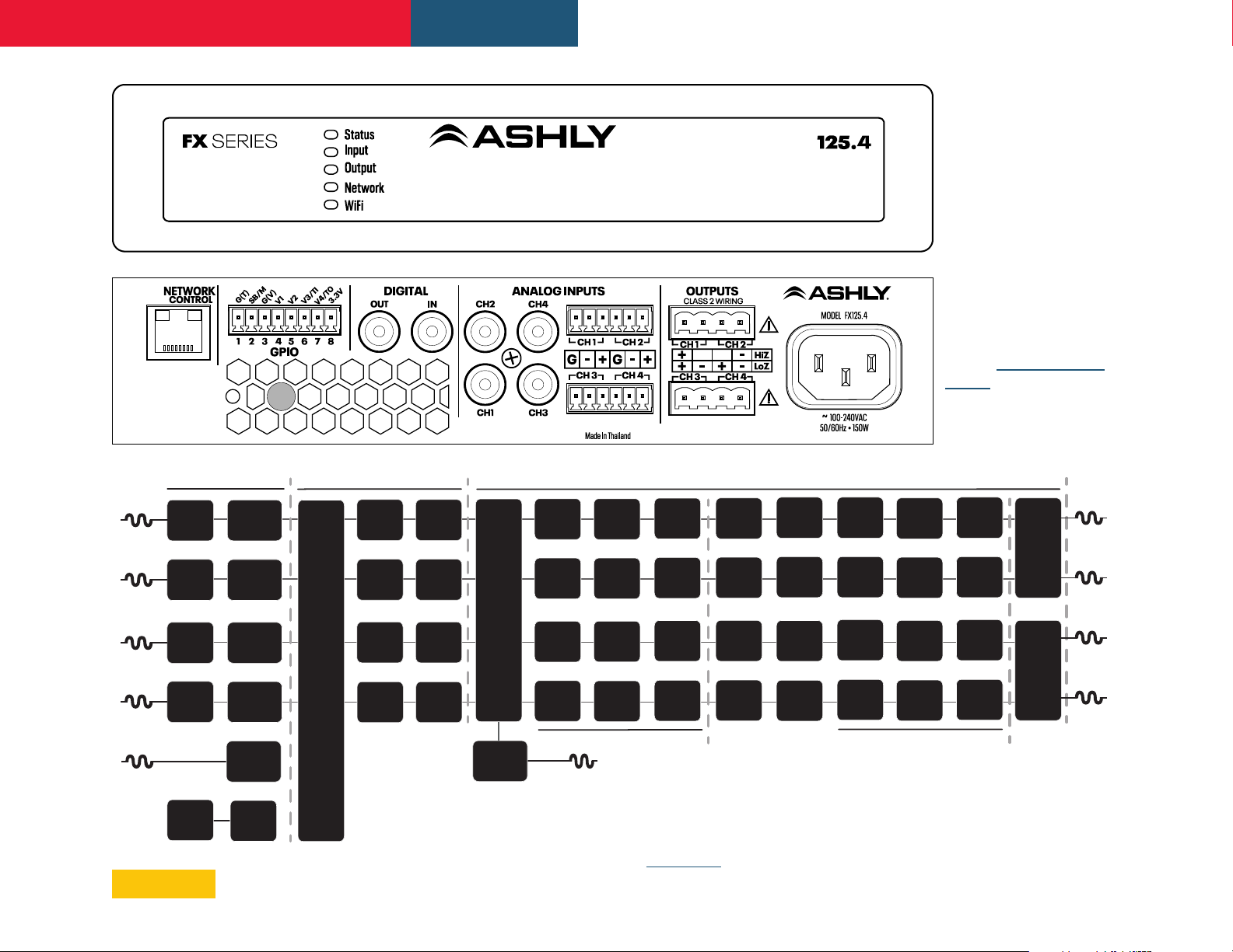
Diagram 10.1:
FX Front & Back Panels,
(FX125.4 shown)
Note: 2-Channel
models are the same as
4-channel models other
than power ratings and
number of available zones
and speaker outputs.
All Network, Input,
GPIO connections, and
functionality are the same
between FX models.
NOTE: FX500 full-rack
models (not shown) share
the same features and
connections as half-rack
models.
Analog 1
Analog 2
Analog 3
Analog 4
SPDIF In (stereo)
Sensivity
Sensivity
Sensivity
Sensivity
Pink Noise
Input
Input
Input
Input
Input Setup
Input
Gain
Input
Gain
Input
Gain
Input
Gain
Input
Gain
Gain
Zone Setup & Routing
Adjustment
Adjustment
Adjustment
Input
Selecon
Adjustment
Level
Level
Level
Level
Compressor
Compressor
Compressor
Compressor
Output
Matrix
Zones A - D
Outputs 1 - 4
Gain Trim
Gain Trim
Gain Trim
Gain Trim
Delay
Delay
Delay
Delay
EQ
EQ
EQ
EQ
Crossover
Crossover
Crossover
Crossover
EQ
EQ
EQ
EQ
Room Adjustment Parameters
Inputs To
Zones
A & B
S/PDIF Out (stereo)
Diagram 10.2: Signal Flow Diagram (4-channel model is shown).
Note: On two-channel models, all four inputs are available, but only
Zones A & B are used for providing signal to the two speaker outputs.
Note: On all FX models, the S/PDIF Out signal is always taken from
the inputs to Zones A & B.
Polarity
Polarity
Polarity
Polarity
Driver
Alignment
Driver
Alignment
Driver
Alignment
Driver
Alignment
Speaker Adjustment Parameters
Output Setup
Limiter
Limiter
Limiter
Limiter
BTL
Amplifier
2 x Low-Z
1 x Hi-Z
BTL
Amplifier
2 x Low-Z
1 x Hi-Z
Output 1
Output 2
Output 3
Output 4
18
Page 19

FX Amplifier • Operating Manual 11. Amplifier Specifications, FX60 & FX125 Models
Model FX 60.2 FX 125.2 FX 60.4 FX 125.4
Outputs 2 Low-Z or 1 Hi-Z 2 Low-Z or 1 Hi-Z 4 Low-Z or 2 Hi-Z 4 Low-Z or 2 Hi-Z
Output power @
4Ω/8Ω/25V†/70V/100V*
All channels driven
Output power @
4Ω/8Ω/25V†/70V/100V*
Single channel driven
Output power @ 16Ω***
Single channel driven
Power Consumption 75W 75W 75W 150W
Thermal Output (BTU/hr,
1/8th Full Power, 4Ω Load)
Dimensions
Weight 2.0 kg (4.4 lbs) 2.0 kg (4.4 lbs) 2.8 kg (6.2 lbs) 2.8 kg (6.2 lbs)
Output Circuitry Class D - full bandwidth PWM modulator with ultra-low distortion
Output Voltage 70 Vp / 140 Vpp (unloaded) / Bridged 140 Vp / 280 Vpp (unloaded)
Signal To Noise-Ratio > 106 dB (A-weighted 20 Hz - 20 kHz 8 Ω load)
THD+N (typical) < 0.05 % (20 Hz - 20 kHz 8 Ω load 12.5% rated power)
Frequency Response 20 Hz - 20 kHz (+0/-0.25 dB (8 Ω load 12.5% rated power)
60W Low-Z
120W Hi-Z
120W** 250W** (156W)
120W 125W 125W 125W
61 78 98 152
44 x 220 x 213 mm
(1.7 x 8.7 x 8.4 in)
125W Low-Z
250W Hi-Z
†
44 x 220 x 213 mm
(1.7 x 8.7 x 8.4 in)
60W Low-Z
120W Hi-Z
250W** 250W** (156W)
44 x 220 x 319 mm
(1.7 x 8.7 x 12.6 in)
125W Low-Z
250W Hi-Z
44 x 220 x 319 mm
(1.7 x 8.7 x 12.6 in)
†
Protection Circuits Short circuit protection. DC protection. under voltage protection. temperature protection. overload protection
Power Supply Universal mains switch mode power supply with Power Factor Correction (PFC) and integral standby converter
Operating Voltage/
Frequency
Standby Consumption < 0.5W
Accessories (sold separately)
Power Ratings 1% THD @ 120VAC and 230VAC
* 100V line mode operates at 90V (≈-1dB)
** Power sharing operational (FX60 and FX125 models only)
*** 16 Ohm power output is limited by the maximum voltage swing available in low impedance mode
†
For 25V applications,maximum power with power sharing is 156W. Output load must be >4Ω
FA1.2RM rack ear, half-rack extension, connection plate; FA2.2RM rear-support kit; FATWB desk/wall mount
Universal Mains 100-240V 50-60Hz
kit, WR-1 & WR-1.1 GPIO Remote Volume Control
19
Page 20
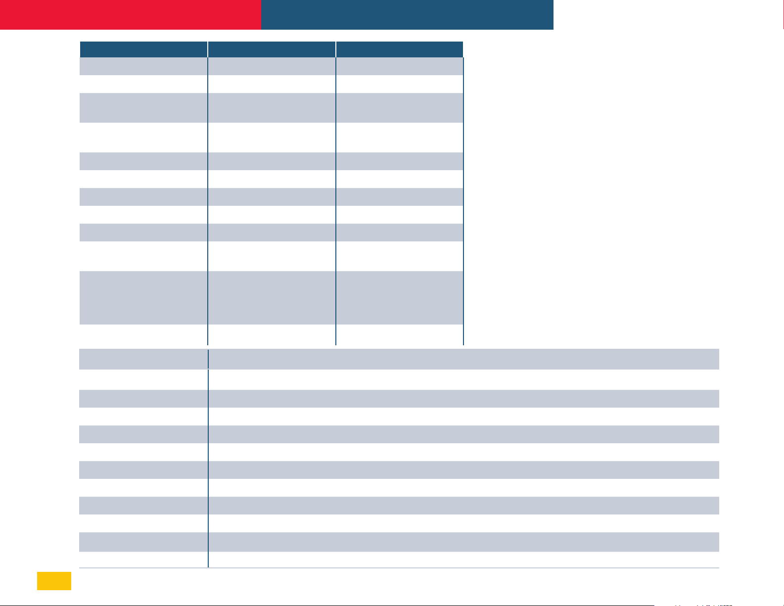
FX Amplifier • Operating Manual 11. Amplifier Specifications, FX500 Models
Model FX 500.2 FX 500.4
Output Channels 2 Low-Z or 1 Hi-Z 4 Low-Z or 2 Hi-Z
Output power @ 2Ω 2 x 500W (SE)* 4 x 500W (SE)
Output power @ 4Ω
Output power @ 8Ω
Output power @ 25V
2 x 500W (SE)
1 x 1000W (BTL)**
2 x 250W (SE)
1 x 500W (BTL)
†
2 x 320W (SE)
†
4 x 500W (SE)
2 x 1000W (BTL)
4 x 250W (SE)
2 x 500W (BTL)
4 x 320W (SE)
†
Output Power @ 70V 1 x 1000W (BTL) 2 x 1000W (BTL)
Output Power @ 100V 1 x 1000W (BTL) 2 x 1000W (BTL)
Total System Power 1000W 2000W
Power Consumption 550W 1100W
Thermal Output (BTU/hr,
1/8th Full Power, 2Ω Load)
Output Voltage
225 436
65Vp/130Vpp
(SE unloaded)
130Vp/260Vpp
(BTL unloaded)
65Vp/130Vpp
(SE unloaded)
130Vp/260Vpp
(BTL unloaded)
Weight 5.9 kg (13 lbs) 7.4 kg (16.3 lbs)
Dimensions 88 x 440 x 332 mm (3.5 x 17.3 x 13.1 in)
Output Circuitry Class D - full bandwidth PWM modulator with ultra-low distortion
Output Voltage 70 Vp / 140 Vpp (unloaded) / Bridged 140 Vp / 280 Vpp (unloaded)
Signal To Noise-Ratio > 108 dB (A-weighted 20 Hz - 20 kHz 8 Ω load)
THD+N (typical) < 0.05 % (20 Hz - 20 kHz 8 Ω load 3dB below rated power)
Frequency Response 20 Hz - 20 kHz (+0/-0.5 dB (8 Ω load 3dB below rated power)
Protection Circuits Short Circuit, Output DC, Undervoltage, Temperature, Overload protection
Power Supply
Universal mains switch mode power supply with Power Factor Correction (PFC) and integral standby converter
Operating Voltage Universal Mains, 100-240V, 50Hz-60Hz
Standby Consumption < 0.5W
Accessories
2x rack ears, 4x adhesive feet (included), WR-1 & WR-1.1 GPIO Remote Volume Control (sold separately)
Power Ratings 1% THD @ 120VAC and 230VAC
*SE - conventional, Single Ended output mode. **BTL - Bridge-Tied Load output mode.
†
For 25V output, set DSP output limiter threshold at 25V using RMS voltage setting.
20
Page 21
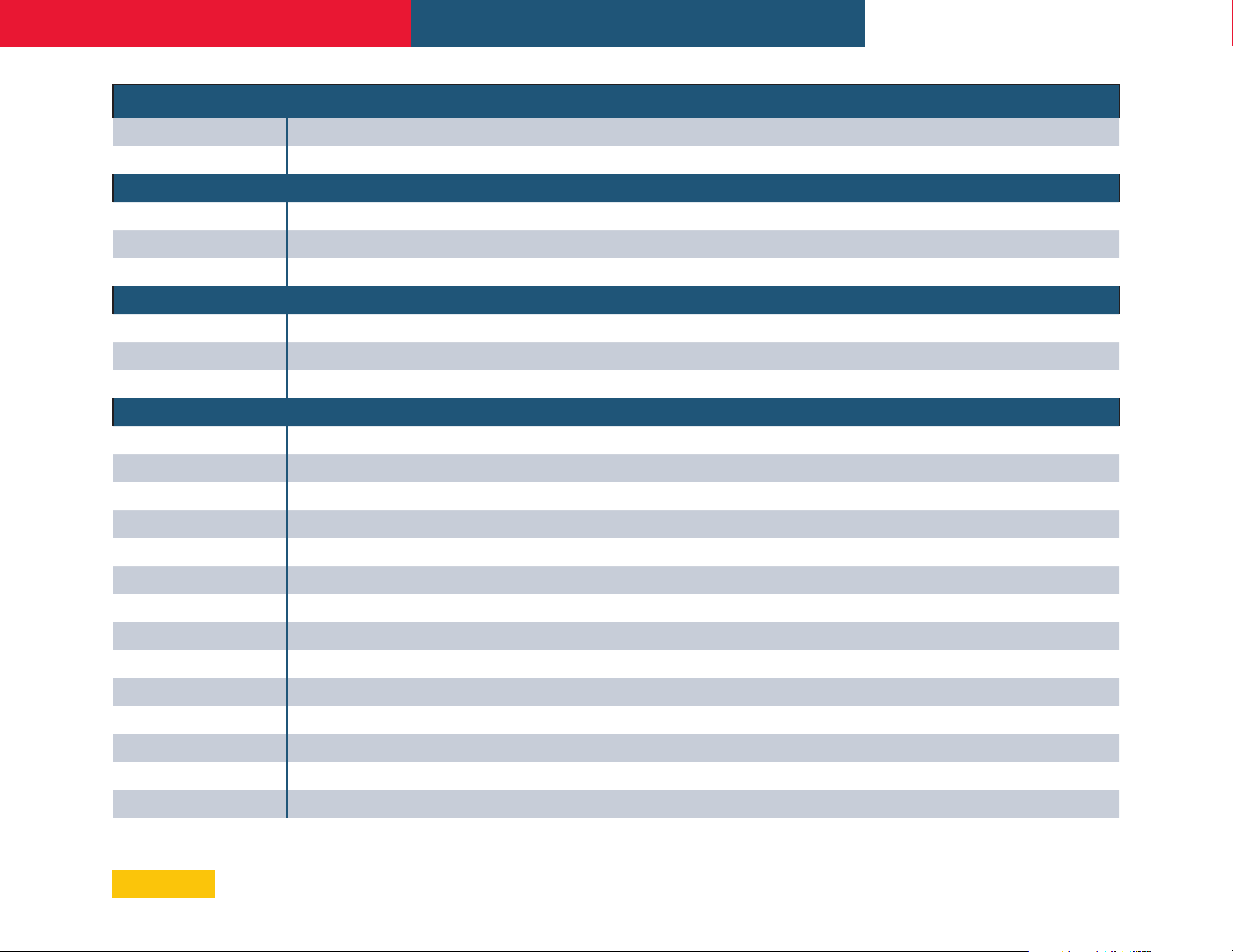
FX Amplifier • Operating Manual 11.1 Configuration (Software) Specifications
Dashboard Menu
Amplifier Status Power/Standby, Input, Output,
Zone Status Mute per zone, Gain adjust -80dB to 0dB, Input Type, Output Routing
Wired LAN IP address, WiFi IP address
Input Menu
Analog Inputs 1-4 Mono or Stereo, Input Sensitivity: +14dBu, +4dBu (default), -10dBV, or Microphone, Gain/Trim -10dB to +10dB
S/PDIF Inputs Mono or Stereo, Gain/Trim -10dB to +10dB
Pink Noise Generator
ON/OFF, Gain/Trim -50dB to 0dB
Zone Menu
Source
GPIO Volume Control
Compressor
Zone A/B in 2ch models, Zone A-D in 4ch models, Gain adjust per zone -80dB to 0dB, Mono or Stereo, Zone Input Source Select
Per Zone, GPIO Pin must be enabled for Volume Control
Per Zone, Default or Manual Mode (manual mode parameters: Threshold, Attack Time, Release Time, Hold Time, Ratio, Knee)
Output Menu
Routing Zone source selection per output 1-2 on 2ch models, output 1-4 on 4ch models
Delay Per output, ON/OFF, adjustable 0-100ms (feet, meters, & samples also indicated)
Equalizer Per output, ON/OFF, Edit, Copy, Clear
Filter Types
Speaker Preset: Per output, select preset from library, import preset from file, export preset to file, clear preset
Crossover & Gain Per output, ON/OFF, Gain, Copy, Clear, High Pass Filter, Low Pass Filter
10-Band Parametric, 6dB & 12dB Hi/Lo Shelf, 6dB & 12dB HPF/LPF, Hi/Lo Shelf with Q, 1st & 2nd order All Pass, Bandpass, Notch
Filter Types Off, Butterworth 6/12/18/24/36/48dB/octave, Bessel 12/24/48dB/octave, Linkwitz-Riley 12/24/36/48dB/octave
Speaker EQ Per output, ON/OFF, Edit, Copy, Clear
Filter Types
FIR Filters Per output, ON/OFF, Import, Clear (512 taps maximum)
Driver Alignment Per output, ON/OFF, adjustable 0-10ms (feet, meters, & samples also indicated)
Polarity Per output, 0, 180
Limiter Per output, Clip Limiter ON/OFF, Peak Limiter (Auto/Manual mode), RMS Limiter ON/OFF
Output Mode Per output, Off, Lo-Z (4 & 8 Ohm), Hi-Z - 70V (needs two output channels), Hi-Z - 100V (needs two output channels)
10-Band Parametric, 6dB & 12dB Hi/Lo Shelf, 6dB & 12dB HPF/LPF, Hi/Lo Shelf with Q, 1st & 2nd order All Pass, Bandpass, Notch
(Continued on next page)
21
Page 22
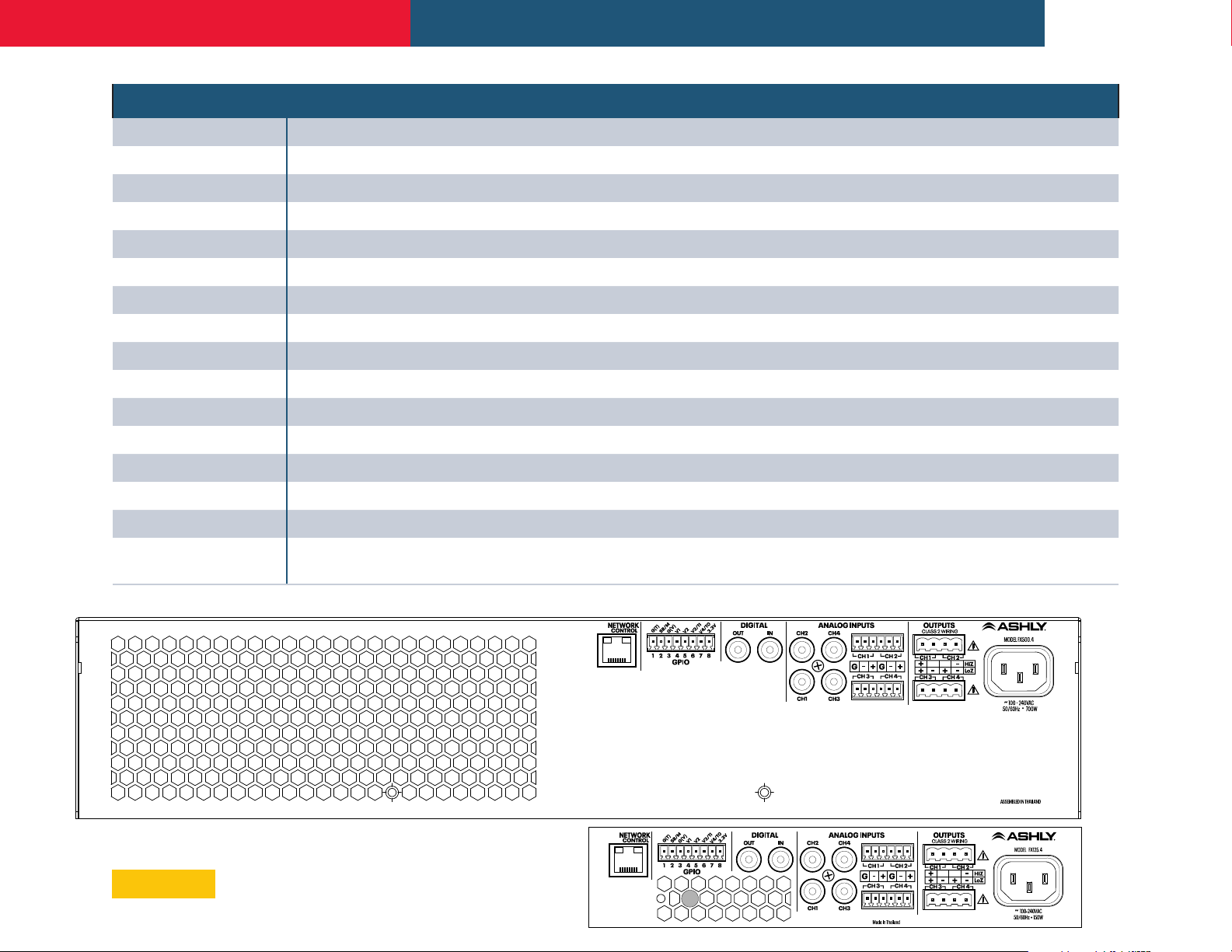
FX Amplifier • Operating Manual
Settings Menu
System Information Installation site info
Device Device info, device locator, firmware update
Backup & Restore Backup/restore device settings, restart device, factory reset
Speaker Library Create/Edit/Import speaker libraries
Power Management Set Auto-On options, change Standby timer, change Mute timer
GPIO Connector Pin assignment options
Pin 1 Ground only, for 12V trigger and standby/mute input reference
Pin 2 Off, Input for Standby (NO), Standby (NC), Mute (NO), or Mute (NC)
Pin 3 Ground only, for Voltage Control and Trigger Out reference
Pin 4 Off, Remote Volume Control
Pin 5 Off, Remote Volume Control
Configuration Specifications (continued)
Pin 6
Pin 7 Off, Remote Volume Control, 12V Trigger Out
Pin 8 3.3V only (used for remote GPIO volume control)
LAN Set LAN network mode to DHCP or Static IP. The wired LAN default static IP address is 192.168.64.100
WiFi WiFi ON/OFF, Disable WiFi on LAN connection, WiFi Disable timer, set WiFi mode to Access Point (hot spot) or Client.
Off, Volume Control, 12V Trigger Input (12V trigger input requires Trigger-Mode selected in Power Management section)
The FX amplifier's WiFi access point (hotspot) IP address is
FX500 models
192.168.4.1, default password is "password"
22
FX60 & 125 models
Page 23

FX Amplifier • Operating Manual
LIMITED WARRANTY (USA ONLY)
(Other countries please contact your
respective distributor or dealer.)
For units purchased in the USA, warranty
service for this unit shall be provided by ASHLY
AUDIO, INC. in accordance with the following
warranty statement.
ASHLY AUDIO, INC. warrants to the owner of
this product that it will be free from defects
in workmanship and materials for a period of
FIVE years from the original-date-of-purchase,
with the exception of touch-screen displays
and motorized faders which are warrantied
for THREE years from the original-date-ofpurchase.
ASHLY AUDIO INC. will without charge, repair or
replace at its discretion, any defective product
or component parts upon prepaid delivery of
the product to the ASHLY AUDIO, INC. factory
service department, accompanied with a proof
of original-date-of-purchase in the form of a
valid sales receipt. This warranty gives you
specific legal rights, and you may also have
other rights, which vary from state to state.
EXCLUSIONS: This warranty does not apply
in the event of misuse, neglect, or as a result
of unauthorized alterations or repairs made
to the product. This warranty is void if the
serial number is altered, defaced, or removed.
ASHLY AUDIO, INC. reserves the right to make
changes in design, or make additions to, or
improvements upon, this product without
any obligation to install the same on products
previously manufactured.
Any implied warranties, which may arise under
the operation of state law, shall be effective
only for FIVE years (THREE years for touchscreen displays and motorized faders) from
the original-date-of-purchase of the product.
ASHLY AUDIO, INC. shall be obligated to only
correct defects in the product itself. ASHLY
AUDIO, INC. is not liable for any damage or
injury, which may result from, or be incidental
to, or a consequence of, such defects. Some
states do not allow limitations on how long
an implied warranty lasts, or the exclusion,
or limitation of incidental or consequential
damages, so the above limitations or
exclusions may not apply to you.
OBTAINING WARRANTY SERVICE:
For warranty service in the United States,
please follow this procedure:a
1) Return the product to ASHLY AUDIO, INC.
freight prepaid, with a written statement
describing the defect and application that
the product is used in. ASHLY AUDIO, INC.
will examine the product and perform any
necessary service, including replacement of
defective parts, at no further cost to you.
2) Ship your product to:
ASHLY AUDIO, INC.
Attention: Service Department
847 Holt Road
Webster, NY 14580-9103
FX R2 09-2022
ASHLY AUDIO INC. 847 Holt Road Webster, NY 14580-9103, USA
Phone: (585) 872-0010 Fax: (585) 872-0739
Toll Free (800) 828-6308 www.ashly.com
©2022 Ashly Audio, a division of Jam Industries USA, LLC. All rights reserved worldwide.
All features, specifications, and graphical representations are subject to change or improvement without notice.
23
 Loading...