

Page 1
Installation and Operating Manual
AGC500VF
WARNING
IF THE INFORMATION IN THIS MANUAL IS NOT FOLLOWED EXACTLY, A FIRE OR EXPLOSION
MAY RESULT CAUSING PROPERTY DAMAGE, PERSONAL INJURY OR LOSS OF LIFE.
• Do not store or use gasoline or other fl ammable vapors and liquids in vicinity of this or any other appliance.
WHAT TO DO IF YOU SMELL GAS:
• Do not try to light any appliance.
• Do not touch any electrical switch; do not use any phone in your building.
• Immediately call your gas supplier from a neighbor's phone. Follow gas supplier's instructions
• If you cannot reach your gas supplier, call fi re department.
• Installation and service must be performed by a qualifi ed installer, service agency or gas supplier.
This is an unvented gas-fi red heater. It uses air (oxygen) from room in which it is installed. Provisions for
adequate combustion and ventilation air must be provided. Refer to section,” Producing Adequate Air
For Combustion And Ventilation". This appliance may be installed in an aftermarket, permanently located,
manufactured (mobile) home, where not prohibited by local codes. This appliance is only for use with type
of gas indicated on rating plate. This appliance is not convertible for use with other gases.
INSTALLER: Leave this manual with appliance.
CONSUMER: Retain this manual for future reference.
This appliance is intended for supplemental heating.
Certifi ed for installations in the USA
Approved for installation in mobile homes
852404-1904E
Page 2

IMPORTANT SAFETY INFORMATION
Congratulations!
PLEASE READ THE INSTALLATION & OPERATING INSTRUCTIONS BEFORE USING APPLIANCE.
Thank you and congratulations on your purchase of an Ashley stove.
IMPORTANT: Read all instructions and warnings carefully before starting installation. Failure to
follow these instructions may result in a possible fi re hazard and will void the warranty.
IMPORTANT: READ THIS OWNER’S MANUAL CAREFULLY AND COMPLETELY BEFORE TRYING TO
ASSEMBLE, OPERATE, OR SERVICE APPLIANCE. IMPROPER USE OF THESE LOGS CAN CAUSE
SERIOUS INJURY OR DEATH FROM BURNS, FIRE, EXPLOSION AND CARBON MONOXIDE
POISONING.
IMPORTANT: VENT-FREE HEATERS ADD MOISTURE TO AIR. ALTHOUGH THIS IS BENEFICIAL,
INSTALLING HEATER IN ROOMS WITHOUT ADEQUATE VENTILATION MAY CAUSE MILDEW TO
FORM FROM TOO MUCH MOISTURE.
WARNING
“ANY CHANGE TO THIS HEATER OR ITS CONTROLS CAN BE DANGEROUS.”
WARNING
• Any change to this heater or its controls can be dangerous.
• Improper installation or use of the heater can cause serious injury or death
from fi re, burns, explosion or carbon monoxide poisoning.
• Do not allow fans to blow directly into the stove. Avoid any drafts that alter burner fl ame patterns.
• Do not use a blower insert, heat exchanger insert or other accessory,
not approved for use with this heater where applicable.
1. Due to high temperatures, the appliance should be located out of traffi c and away from furniture and draperies.
2. Children and adults should be alerted to the hazard of high surface temperature and should stay away to
avoid burns or clothing ignition.
3. Young children should be carefully supervised when they are in the same room with the appliance.
4. Do not place clothing or other fl ammable material on or near the appliance.
5. Any safety screen or guard removed for servicing an appliance, must be replaced prior to operating the heater.
6. Installation and repair should be done by a qualifi ed service person.
7. To prevent malfunction and/or sooting, an unvented gas heater should be cleaned before use and at least
annually by a professional service person. More frequent cleaning may be required due to excessive lint
from carpeting, bedding material, etc. It is imperative that control compartments, burners and circulating air
passageways be kept clean.
8. CARBON MONOXIDE POISONING: Early signs of carbon monoxide poisoning are similar to the fl u with headaches,
dizziness and/or nausea. If you have these signs, obtain fresh air immediately. Have the heater serviced as it
may not be operating properly.
9. The installation must conform with local codes or, in the absence of local codes, with the National Fuel Gas
Code, ANSI Z223.l/NFPA54.
10. This unit complies with the latest edition of ANSI Z21.11.2, Unvented Heaters.
11. Do not install heater in a bathroom or bedroom unless approved for bedroom use.
12. Correct installation of the ceramic fi ber logs, proper location of the heater, and annual cleaning are necessary
to avoid potential problems with sooting. Sooting, resulting from improper installation or operation, can settle
on surfaces outside the fi replace. See log placement instructions for proper installation.
2
Page 3
IMPORTANT SAFETY INFORMATION
13. Avoid any drafts that alter burner fl ame patterns. Do not allow fans to blow directly into fi replace. Do not place
a blower inside burn area of fi rebox. Ceiling fans may create drafts that alter burner fl ame patterns. Sooting
and improper burning will occur.
14. Caution: Candles, incense, oil lamps, etc. produce combustion by-products including soot. Vent-free appliances
will not fi lter or clean soot produced by these types of products. In addition, the smoke and/or aromatics
(scents) may be reburnt in the vent-free appliance which can produce odors. It is recommended to minimize
the use of candles, incense, etc. while the vent-free appliance is in operation.
15. This is an unvented gas-fi red heater. It uses air (oxygen) from the room in which it is installed. Provisions for
adequate combustion and ventilation air must be provided.
16. This heater shall not be installed in a room or space unless the required volume of indoor combustion air is
provided by the method described in the National Fuel Gas Code, ANSI Z223.1/NFPA 54, the International Fuel
Gas Code or applicable local codes.
17. Keep room area clear and free from combustible materials, gasoline and other fl ammable vapors and liquids.
18. Unvented gas heaters are a supplemental zone heater. They are not intended to be a primary heating
appliance.
19. Unvented gas heaters emit moisture into the living area. In most homes of average construction, this does not
pose a problem. In houses of extremely tight construction, addition mechanical ventilation is recommended.
20. During manufacturing, fabricating and shipping, various components of this appliance are treated with certain
oils, fi lms or bonding agents. These chemicals are not harmful but may produce annoying smoke and smells
as they are burned off during the initial operation of the appliance; possibly causing headaches or eye or
lung irritation. This is a normal and temporary occurrence. The initial break-in operation should last two to three
hours with the burner at the highest setting. Provide maximum ventilation by opening windows or doors to
allow odors to dissipate. Any odors remaining after this initial break-in period will be slight and will disappear
with continued use.
21. Input ratings are shown in BTU per hour and are for elevations up to 2,000 feet. For elevations above 2,000
feet, input ratings should be reduced 4 percent for each 1,000 feet above sea level. Refer to the National
Fuel Gas Code.
22. The appliance and its appliance main gas valve must be disconnected from the gas supply piping system
during any pressure testing of that system at test pressures in excess of 1/2 psig (3.5 kPa).
23. The appliance must be isolated from the gas supply piping system by closing its equipment shutoff valve during
any pressure testing of the gas supply piping system at test pressures equal to or less than 1/2 psig (3.5 kPa).
24. Do not use this room heater if any part has been under water. Immediately call a qualifi ed service technician
to inspect the room heater and to replace any part of the control system and any gas control which has
been under water.
25. Never burn solid fuels in an unvented room heater, fi replace or stove.
26. Do not set kettles or humidifying devices on top of stove.
27. The stove door/screen must be closed when the appliance is operating. The screen shall have openings for
induction of combustion air.
CODES
Adhere to all local codes or, in their absence,
the latest edition of THE NATIONAL FUEL
GAS CODE ANSI Z21.88/CSA 2.33-2014 or
NFPA54 which can be obtained from…
American National Standards Institute, Inc.
1430 Broadway
New York, NY 10018
or
National Fire Protection Association, Inc.
Batterymarch Park
Quincy, MA 02269
Proposition 65 Warning: Fuels used in gas, wood burning or oil fi red appliances, and the products of combustion of
such fuels, contain chemicals known to the State of California to cause cancer, birth defects and other reproductive
harm.
California Health & Safety Code Sec. 25249.6
3
Page 4
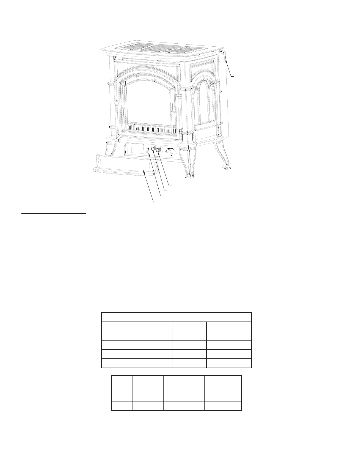
PRODUCT FEATURES
On/Off Switch
OFF
Off/Pilot/On Knob
Hi/Lo Knob
Piezo
Door
IGNITION CONTROLS
Piezo ignitor allows ignition of the pilot without the use of matches.
Millivolt control has four (4) positions:
OFF - All gas to the burner is shut off at the valve.
IGN - Valve position to light/maintain a standing pilot.
ON - Valve position to turn burners ON/OFF.
LOW/HI - Variable position to control fl ame height (heat output). Both front and rear burners
are in operation to provide realistic glow and yellow fl ame.
PILOT /ODS
The gas log heater is fi tted with a specially designed safety pilot (ODS assembly) light which senses the amount
of oxygen available in the room and shuts the gas log heater off if the oxygen level begins to drop below a
satisfactory level. The pilot can only be relit when adequate fresh air is available.
Gas Pressures
Natural Propane (LP)
Regulator Pressure 3.5” w.c. 10.0” w.c.
Pilot Regulator 3.5” w.c. n/a
Max. Gas Inlet Pressure 10.5” w.c. 13.0” w.c.
Min. Gas Inlet Pressure 5.0" w.c. 11.0" w.c.
Fuel Control
Max. Input
BTU/h
Nat. Millivolt 32,000 23,000
LP Millivolt 32,000 23,000
NOTE: An external regulator is required to reduce supply pressure to a maximum of 10.5" w.c. on Natural Gas
systems operating at higher pressure.
NOTE: An external regulator is required to reduce supply pressure to a maximum of 13.0" w.c. for LP systems.
Min. Input
BTU/h
4
Page 5
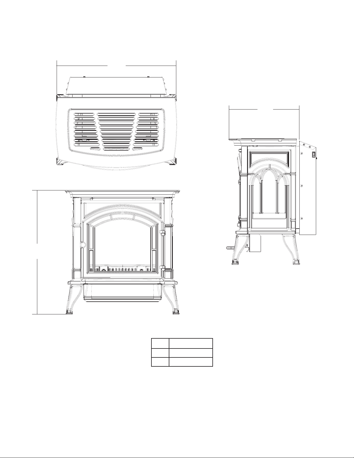
A
DIMENSIONS
C
B
A 26” (660mm)
B 16” (406mm)
C 29” (737mm)
5
Page 6

GETTING STARTED
CAUTION: GLOVES ARE RECOMMENDED WHEN HANDLING CERAMIC FIBER LOGS TO
PREVENT SKIN IRRITATION FROM LOOSE FIBERS. LOGS ARE FRAGILE — HANDLE WITH CARE.
MAKE SURE YOU HAVE RECEIVED ALL PARTS
Check your packing list to verify that all listed parts have been received. You should have the following:
• Cast Iron Stove with Burner Assembly
• Installation/Operating Instructions
• Ceramic Fiber Logs
Carefully inspect the contents for shipping damage. If any parts are missing or damaged, immediately inform
the dealer from whom you purchased the appliance. Do not attempt to install any part of the appliance
unless you have all parts in good condition.
WHAT THE GAS TECHNICIAN WILL NEED FOR INSTALLATION
You must have the following items available before proceeding with installation:
• External regulator (for Propane/LPG) or high pressure natural gas (1 to 2 psi system)
• Piping which complies with local codes
• Sediment trap (recommended)
• Pipe wrench
• Pipe sealant approved for use with propane/LPG (resistant to sulfur compounds)
• Manual shutoff valve
• Tee joint
• Screwdrivers
WARNING
DO NOT INSTALL THE HEATER …
• Where curtains, furniture, clothing, or other fl ammable objects are less than 42” from the heater.
• In high traffi c areas.
• In windy or drafty areas.
WARNING
IF THE AREA IN WHICH THE HEATER MAY BE OPERATED DOES NOT MEET THE REQUIRED VOLUME
FOR INDOOR COMBUSTION AIR, COMBUSTION AND VENTILATION AIR SHALL BE PROVIDED
BY ONE OF THE METHODS DESCRIBED IN THE NATIONAL FUEL GAS CODE, ANSI Z223.1/NFPA
54, THE INTERNATIONAL FUEL GAS CODE OR APPLICABLE LOCAL CODES.
6
Page 7
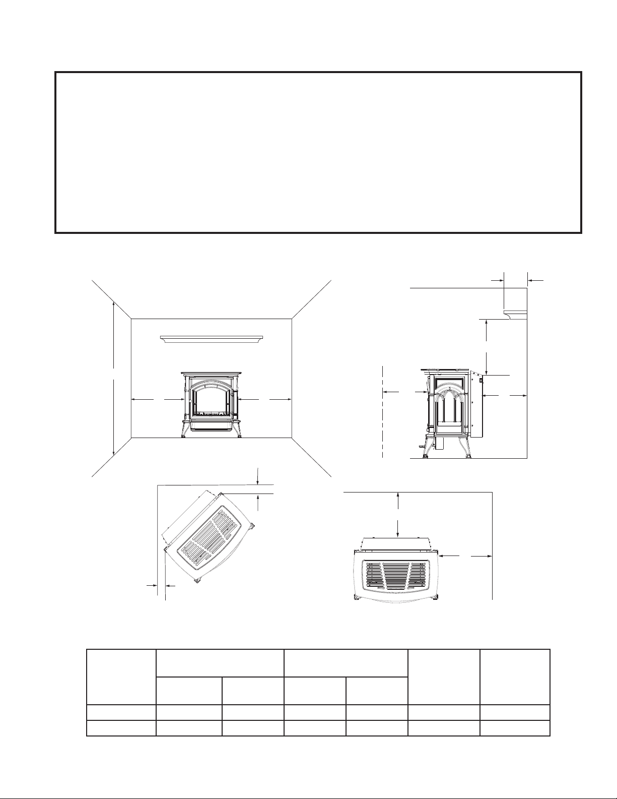
CLEARANCES AND HEIGHT REQUIREMENTS
WARNING
THE DIMENSIONS SHOWN ARE MINIMUM CLEARANCES TO MAINTAIN IN INSTALLING THIS
HEATER. LEFT AND RIGHT CLEARANCES ARE DETERMINED WHEN FACING THE FRONT OF THE
HEATER. FOLLOW THESE INSTRUCTIONS CAREFULLY TO ENSURE SAFE INSTALLATION. FAILURE
TO FOLLOW INSTRUCTIONS EXACTLY CAN CREATE A FIRE HAZARD. THE APPLIANCE CANNOT
BE INSTALLED ON A CARPET, TILE OR OTHER COMBUSTIBLE MATERIAL. THE APPLIANCE SHALL
BE INSTALLED ON A NONCOMBUSTIBLE MATERIAL PANEL EXTENDING THE FULL WIDTH AND
DEPTH OF THE APPLIANCE.
ide
all
Ceiling
Ceiling
Mantel
A
E
Minimum
Front View
G
Corner Installation
D
Minimum
to Either
Side Wall
G
Wall Installation
Side View
36"
in Front
F Minimum
D
Minimum
to Either
Side Wall
B
C
F
Minimum
Figure 4 -
Minimum Clearances
Min
Ceiling
From Floor
Mantel Clearance
From Top Of Unit Side Measured From
Max.
Protrusion
Min.
Height Right Left
Rear
Measured
From Back
Corner
Measured
From Top
Corners
A B C D E F G
72" 12" 18" 2" 2" 1" 1/2
7
Page 8
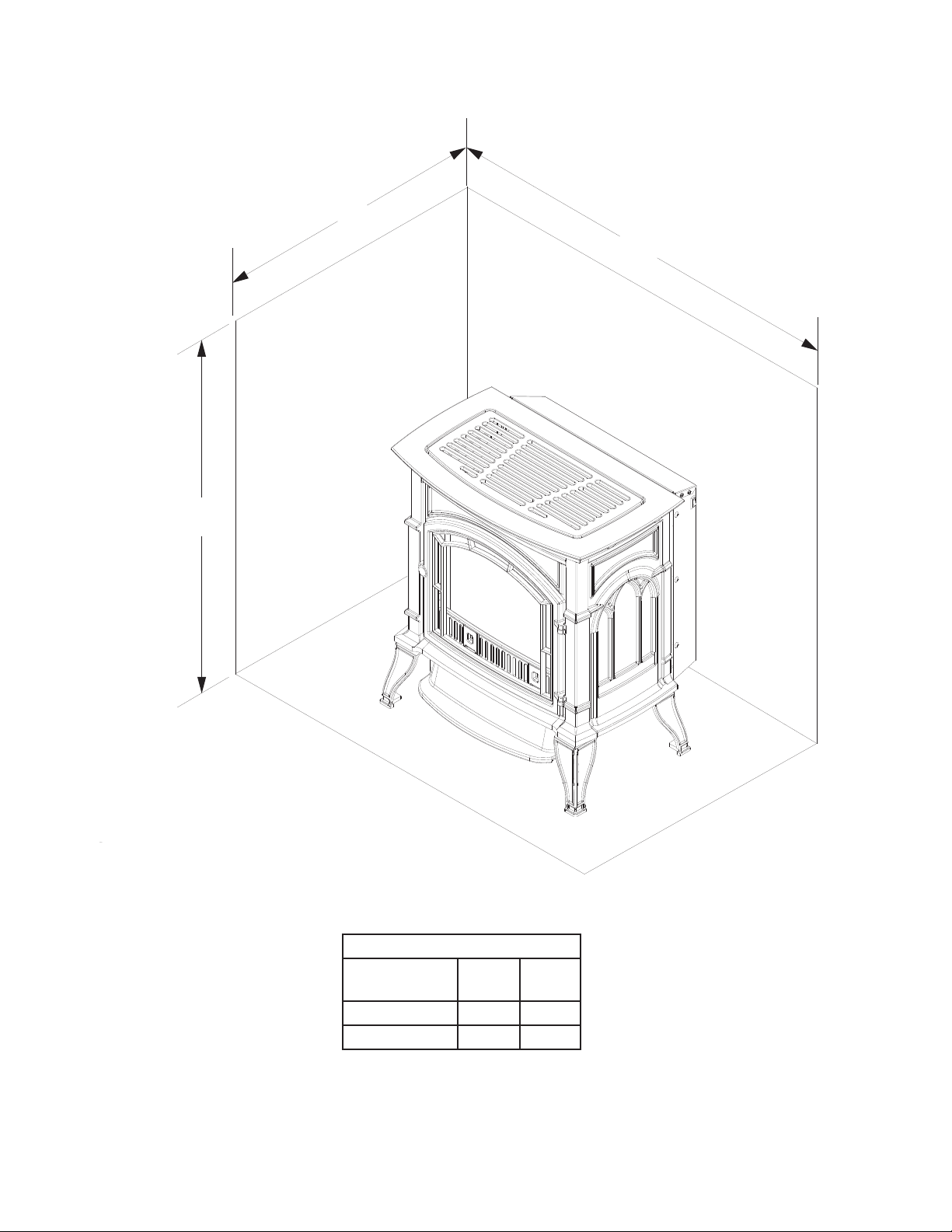
CLEARANCES/HEIGHT REQUIREMENTS
C
B
A
Figure 5 -
Alcove Installation
NOTE: Maintain minimum side and back clearances when placing stove in alcove.
8
Alcove Minimum Dimensions
Height From
Hearth
A B C
52” 34” 36”
Width Depth
Page 9
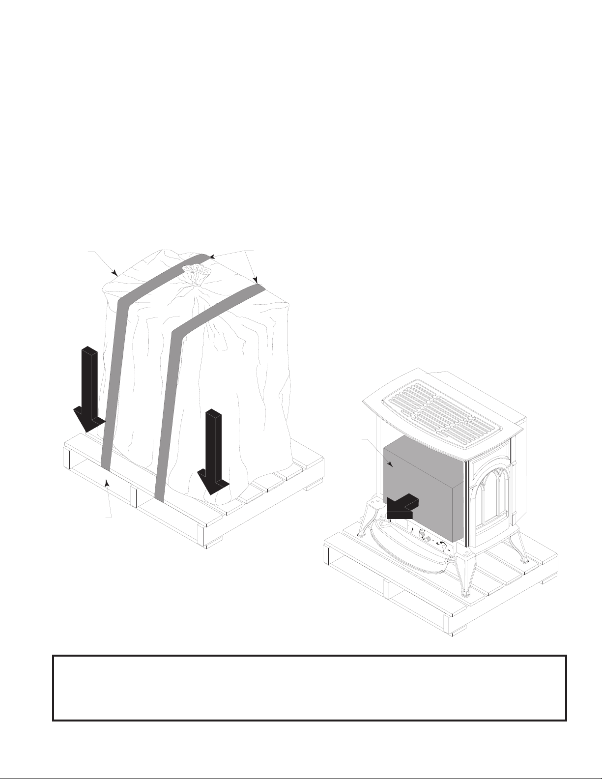
INSTALLATION
1. Remove two (2) straps.
2. Open plastic bag and slide to bottom of unit.
3. Lift up on ash lip and pivot down to open control door.
4. Lift up on front. Pivot bottom of front out. Remove front.
5. Open and remove glass door.
6. Remove log box from inside of unit.
7. Lift unit off pallet. Lift unit up high enough to clear upright supports unit is sitting on.
NOTE: You will need at least two (2) strong people to lift unit off of pallet.
Plastic
Bags
LOGS
Pallet
Figure 6 -
Remove Straps and Plastic from Unit
Straps
ON
OFF
Log Box
LOGS
PI
LO
T
O
F
F
Figure 7 -
Remove Log Box
CAUTION! THE APPLIANCE IS VERY HEAVY. THE ASSISTANCE FROM A SECOND
PERSON IS STRONGLY SUGGESTED. PLEASE USE PROPER LIFTING TECHNIQUE
WHEN POSITIONING THE APPLIANCE FOR ASSEMBLY AND INSTALLATION.
9
Page 10

CONNECT GAS LINE
WARNING
Use new black iron or steel pipe. Internally tinned copper or copper tubing can be used per National Fuel
Code, section 2.6.3, providing gas meets hydrogen sulfi de limits, and where permitted by local codes. Gas
piping system must be sized to provide minimum inlet pressure (Listed on Data Plate) at the maximum fl ow
rate (BTU/hr). Undue pressure loss will occur if the pipe is too small.
A manual shutoff valve must be installed upstream of the appliance. Union tee and plugged 1/8" NPT pressure
tapping point should be installed upstream of the appliance. A sediment trap should be installed upstream to
prevent moisture and contaminants from passing through the pipe to appliance controls and burners. Failure
to do so could prevent the appliance from operating reliable.
NOTICE: A qualifi ed gas appliance installer must connect the heater to the gas supply. Consult all local codes.
To Heater
Valve
Pipe Coupling
Stainless
Flexible
Tube
Pipe
Locations that the
Pressure Tapping
Point May Be
Installed
Gas
Supply
Inlet
Manual Shutoff Valve
Figure 8 -
Gas Connection
IMPORTANT: Hold heater valve fi rmly with a wrench to prevent movement when connecting to inlet pipe.
Always use an external regulator for all propane/LPG heaters and high pressure one to two-pound systems
only, to reduce the supply tank pressure to a maximum of 13" w. This is in addition to the internal regulator
in the heater valve.
CHECK GAS TYPE : The gas supply must be the same as stated on the heater’s rating plate. If the gas supply
is different, DO NOT INSTALL THE HEATER. Contact your dealer for the correct model.
10
Page 11

ELECTRICAL WIRING (MILLIVOLT)
The millivolt valve is a self-powered combination gas control THAT DOES NOT REQUIRE 110V AC TO OPERATE .
CAUTION: LABEL ALL WIRES PRIOR TO DISCONNECTION WHEN SERVICING
CONTROLS. WIRING ERRORS CAN CAUSE IMPROPER AND DANGEROUS
OPERATION. VERIFY PROPER OPERATION AFTER SERVICING.
CONNECT OPTIONAL WALL SWITCH
1. Use 18 awg, two-wire cable, 15 feet maximum length.
2. At one end of the cable, connect both wires to the wall switch. At the other end, connect one wire to
TP/TH and one wire to TH, or connect the wall switch to the two male (0.25") terminals on the left side of
the unit.
CHECK SYSTEM OPERATION
The millivolt system and individual components may be checked with a millivolt meter having a 0-1000 mV
range. Conduct each check shown in chart below by connection meter test leads to terminals as indicated.
A. Complete Millivolt System Check
(“A” Reading - Thermostat contacts CLOSED - Control Knob “ON” - Main burner should turn ON)
a. If the reading is more than 100 millivolts and the automatic valve still does not come on, replace the
control.
b. If the closed circuit reading (“A” reading) is less than 100 millivolts, determine cause for low reading,
proceed to Section B below.
B. Thermopile Output Reading Check
(“B” Reading - Thermostat contacts OPEN - Main burner OFF)
1. Check gas pressure to the unit. If gas pressure is within minimum and maximum on data plate, then check
pilot voltage, 325 millivolts minimum. If the minimum millivolt reading is not obtainable, replace pilot.
Check
Test
To Test
Connect
Meter Leads
to Terminals
Switch or
Thermostat
Contacts
Meter Reading
Should Be
A Complete System 2 & 3 Closed Closed
B Thermopile 1 & 2 Open Open
CONNECTION
1 = TP
2 = TP, TH
3 = TH
Wall
Switch
On/Off
Switch
Optional Wall
Switch or
Remote
On/Off
Switch
ODS Pilot
3
1
2
Millivolt Valve
Spade Terminal
ODS Pilot
Figure 10 -
Wiring Diagram
Switch
11
Page 12

LOG PLACEMENT
WARNING
The positioning of the logs is critical to the safe and clean operation of this heater. Sooting and other problems
may result if the logs are not properly and fi rmly positioned in the appliance. Never add additional logs or
embellishments such as pine cones, vermiculite or rock wool to the heater. Only use the logs supplied with
the unit.
Failure to position the parts in accordance with diagrams below or to use only parts specifi cally approved
for this heater may result in property damage or personal injury.
Before you begin — This unit is supplied with fi ve
ceramic fi ber logs. Do not handle these logs with
your bare hands. Always wear gloves to prevent
skin irritation from ceramic fi bers. After handling
the logs, wash your hands gently with soap and
water to remove any traces of fi bers.
LOG PLACEMENT
1. Install back log (#1) on rear log support
bracket.
2. Install left bottom log (#2) on left log support
bracket in front of back log.
3. Install right bottom log (#3) on right log
support bracket in front of back log.
4. Install top left log (#4) on top of left bottom
log.
5. Install top right log (#5) on top of right bottom
log.
Top Left
Log #4
Left Bottom
Log #2
Right Top
Log #5
Right
Bottom
Log #3
Back Log #1
Left Log
Support
Bracket
PI
LO
T
OFF
Right Log
Support Bracket
Rear Log
Support
Bracket
Figure 12 -
Place Logs on Grate
CAUTION:
During initial operation of the new heater, burning logs will give off a paper burning smell and orange fl ames
will be present. Simply open the windows for a few hours to vent the odor.
12
Page 13

FLAME APPEARANCE
T
Flames from the pilot, front and rear burner should be visually checked as soon as the heater is installed. In
addition, periodically check the fl ames visually during operation.
PILOT FLAME
The pilot fl ame must always be present when the heater is in operation. It should just touch the top of the
thermocouple tip for natural. Refer to the fi gure below for correct pilot fl ame.
If the pilot fl ame does not touch the thermocouple, then the burners cannot function reliably. Refer to the
fi gure below for incorrect shape of pilot fl ame.
MILLIVOLT CONTROL
Thermocouple
for Natural
Thermocouple
for Natural
Thermocouple
for LP
Figure 13-
Correct Pilot Flame Appearance
Thermocouple
for LP
Figure 14 -
Incorrect Pilot Flame Appearance
PILO
T
Figure 15-
Correct Burner Flame Appearance
BURNER FLAME
In normal operation at full rate after 15 minutes, the following fl ame appearances should be observed: The
left and right rear fl ames should be yellow and extend 1"- 2" above middle logs. The yellow fl ames should
not contact the logs. There should be glowing embers on the front surface of the middle log.
NOTE The fl ames and embers will be an opaque orange color during the burn off time.
13
Page 14

OPERATING INSTRUCTIONS
OPERATING INSTRUCTIONS
Avoid any drafts that alter burner fl ame patterns. Do not allow fans to blow directly into the stove. Do not
place a blower inside the burn area of the stove. Ceiling fans may create drafts that alter fl ame patterns.
Sooting and improper burning will result.
During manufacturing, fabricating and shipping, various components of this appliance are treated with
certain oils, fi lms or bonding agents. These chemicals are not harmful, but may produce annoying smoke
and smells as they are burned off during the initial operation of the appliance, possibly causing headaches
or eye or lung irritation. This is a normal and temporary occurrence.
The initial break-in operation should last two to three hours with the burner at the highest setting. Provide
maximum ventilation by opening windows or doors to allow odors to dissipate. Any odors remaining after
this initial break-in will be slight and will disappear with continued use.
FOR YOUR SAFETY READ BEFORE LIGHTING
WARNING
IF YOU DO NOT FOLLOW THESE INSTRUCTION EXACTLY, A FIRE OR EXPLOSION MAY RESULT
CAUSING PROPERTY DAMAGE, PERSONAL INJURY OR LOSS OF LIFE.
A. This appliance is equipped with an ignition device which automatically lights the pilot. If the piezo is not
working properly, refer to Match Lighting instructions.
B. BEFORE OPERATING smell all around the appliance area for gas. Be sure to smell next to the fl oor because
some gas is heavier than air and will settle on the fl oor.
WHAT TO DO IF YOU SMELL GAS:
• Turn off all gas to the appliance.
• Open windows.
• Do not attempt to light any appliance.
• Do not touch any electric switch; do not use any phone in your building.
• Immediately call your gas supplier from a neighbor's phone. Follow the gas supplier's instructions.
If you cannot reach your gas supplier, call the fi re department.
C. Use only your hand to push in, or turn the gas control knob. Never use tools. If the knob will not push in
or turn by hand, don't try to repair it. Call a qualifi ed service technician. Force or attempted repair may
result in a fi re or explosion.
D. Do not use this appliance if any part of it has been under water. Immediately call a qualifi ed service
technician to inspect the appliance and to replace any part of the control system and any gas control
that has been under water.
14
Burner Controls - Piezo
Ignitor, Control Knobs
Piezo
Hi/Lo Knob
Off/Pilot/On Knb
Pilot
PI
L
O
T
OFF
Page 15

OPERATING INSTRUCTIONS
MILLIVOLT CONTROL LIGHTING INSTRUCTIONS
1. STOP! Read the safety information label.
2. Make sure the manual shutoff valve is fully open.
3. This gas log set is equipped with an ignition device (piezo) which automatically lights the pilot. If piezo
ignitor does not light the pilot, refer to instructions for “Match Lighting Instructions”.
4. Turn gas control knob clockwise to the OFF position, and turn ON/OFF switch to OFF position.
5. Wait (5) minutes to clear out any gas. Then smell for gas, including near the fl oor. If you smell gas, STOP!
Follow “What to Do if You Smell Gas”. If you don't smell gas, go to next step.
6. From OFF position, turn the gas control knob counterclockwise to IGN position. Push in control knob for 5
seconds. NOTE: If you are running the heater for the fi rst time, it will be necessary to press in the control
knob for 30 seconds to allow air to bleed out of the gas piping.
7. With the control knob pushed in, push in and release the piezo ignitor button to light the pilot.
8. Continue pushing the control knob in for a further 10 seconds to prevent the fl ame detector from shutting
off the gas while the probe is warming up. Release the control knob.
9. Turn gas control knob counterclockwise to the ON position.
10. After the pilot has been lit for one minute, the burners can be turned on. Turn the ON/OFF switch to ON
position.
11. If the gas logs will not operate, follow the instructions “To Turn Off Gas To Heater” below and call your
service technician or gas supplier.
ON
OFF
Hi/Lo Control
Ignitor/Pilot
Control
Pilot
Control Cover Plate for Millivolt
TO TURN OFF GAS TO HEATER
1. Turn ON/OFF switch to OFF position.
2. Turn control knob clockwise to OFF position to completely shut off the heater.
3. If applicable: Turn off all electric power to the heater.
MATCH LIGHTING INSTRUCTIONS
1. Open stove door. Remove any items necessary for easy access to the pilot (for example: logs, screens,
etc.).
2. Follow appropriate lighting instructions found previously. Instead of pushing and releasing the piezo
button, light a match and hold the fl ame to the end of the pilot and ignite the pilot.
3. After control knob has been released and pilot stays lit, reinstall any items that were removed for pilot
access.
4. Call a qualifi ed service technician for repair or replacement of the piezo ignitor.
On/Off Switch
(Located on Side of
Stove)
15
Page 16

CLEANING AND SERVICING
WARNING
TURN OFF HEATER AND ALLOW TO COOL BEFORE CLEANING. DISCONNECT ELECTRICAL POWER
BEFORE CLEANING OR SERVICING.
CLEANING AND SERVICING
Annual inspection and cleaning by your dealer or qualifi ed service technician is recommended to prevent
malfunction and/or sooting.
Remove logs, handling carefully by holding gently at each end. Gloves are recommended to prevent skin
irritation from ceramic fi bers. If skin becomes irritated, wash gently with soap and water. Refer to manual for
correct log placement.
Periodic Cleaning - See parts diagram for location of items discussed below.
• Do not use cleaning fl uid to clean logs or any part of heater.
• Brush logs with soft bristle brush or vacuum with brush attachment.
• Vacuum loose particles and dust from the front and rear burners, control and piezo covers and grate
weldment.
• Inspect and clean burner air intake holes. Remove lint or particles with vacuum, brush, or pipe cleaners.
Failure to keep air intake holes clean will result in sooting and poor combustion.
• External case should be dusted and wiped with a moist cloth.
Annual Cleaning /Inspection - Refer to parts diagram for location of items discussed below.
• Inspect and clean burner air intake holes. Remove lint or particles with vacuum, brush or pipe cleaners.
Failure to keep air intake holes clean will result in sooting and poor combustion.
• Inspect and clean all burner ports.
• Inspect ODS pilot for operation and accumulation of lint at air intake holes.
• Verify fl ame pattern and log placement for proper operation.
• Verify smooth and responsive ignition of main burner and rear burner.
16
Page 17

TROUBLESHOOTING
WARNING
TURN APPLIANCE OFF AND ALLOW TO COOL BEFORE SERVICING. ONLY A QUALIFIED SERVICE
PERSON SHOULD SERVICE AND REPAIR THE HEATER.
NOTE: All troubleshooting items are listed in order of operation.
OBSERVED PROBLEM POSSIBLE CAUSE REMEDY
When ignitor button is
pressed, there is no spark at
ODS/pilot.
Appliance produces
unwanted odors.
Appliance shuts off during
use.
Gas odor even when control
knob is in OFF position.
1. Ignitor electrode positioned wrong.
2. Ignitor electrode is broken.
3. Ignitor electrode not connected to
ignitor cable.
4. Ignitor cable pinched or wet. Keep
ignitor cable dry.
5. Broken ignitor cable.
6. Bad piezo ignitor.
1. Appliance burning vapors from paint,
hair spray, glues, etc.
2. Gas leak.
3. Initial burn off.
1. Not enough fresh air is available for
ODS/ pilot to operate.
2. Low line pressure.
3. ODS/pilot is partially clogged.
4. Defective Thermopile.
5. Restrictions in incoming air flow.
1. Gas leak.
2. Control valve defective.
1. Replace ignitor.
2. Replace ignitor.
3. Reconnect ignitor cable.
4. Free ignitor cable if
pinched by any metal or
tubing.
5. Replace ignitor cable.
6. Replace piezo ignitor.
1. Ventilate room. Stop using
odor causing products
while heater is running.
2. Locate and correct all
leaks.
3. Ventilate room and turn
unit on high until odor is
gone. Odor should be gone
after 6 hours of continuous
use.
1. Open window and/or door
for ventilation.
2. Contact local gas
company.
3. Clean ODS/pilot.
4. Check pilot flame, check
wire connections, check
output, should be 325
millivolts across TH/TP and
TP Terminals with ON/OFF
switches off.
5. Check for bottom riser
on glass door, sunken
fireplace, excessive lava
rock/cinders densely
packed against grate.
Locate and correct all leaks.
Replace control valve.
17
Page 18

TROUBLESHOOTING
WARNING
IF THE GAS QUALITY IS BAD, YOUR PILOT MAY NOT STAY LIT, THE BURNERS MAY PRODUCE
SOOT AND THE HEATER MAY BACKFIRE WHEN LIT. IF THE GAS QUALITY OR PRESSURE IS LOW,
CONTACT YOUR LOCAL GAS SUPPLIER IMMEDIATELY.
OBSERVED PROBLEM POSSIBLE CAUSE REMEDY
1. Press in control knob fully.
2. After ODS/pilot lights, keep
control knob pressed in for 30
seconds.
3. Fully open manual shutoff
valve.
4. Hand tighten thermocouple
connection until snug, then
tighten 1/4 turn more.
5a. Contact local gas company.
5b. Clean pilot with vacuum
cleaner.
6. Replace thermocouple.
7. Replace control valve.
1. Clean orifice.
2. Replace burner orifice.
3. Contact qualified service
person
1. Contact local gas company.
2. Clean burner or replace burner
orifice.
1. Clean burner or replace burner
orifice.
2. Replace burner.
3. Replace gas regulator.
1. Problem will stop after a few
hours of operation. Run the
heater with the damper open
if you have one, or open a
window for the first few hours.
2. Log heater is intended to be
smokeless. Turn OFF heater and
call qualified service person.
1. Turn control knob to LOW
position and let warm up for a
minute.
2. Operate burner until air is
removed from line. Have gas
line checked by local gas
company.
3. Clean burner or replace burner
orifice.
1. Verify LP tank regulator is
installed and set at 11” to 13”
w.c.
2. Replace regulator on heater.
ODS/pilot lights,
but flame goes out
when control knob is
released.
Burner does not light
after ODS/pilot is lit.
Burner backfires
during combustion.
Slight smoke or
odor during initial
operation.
Logs appear to
smoke after initial
operation.
Heater produces
a whistling noise
when burner is lit.
No gas to pilot.
1. Control knob not fully pressed in.
2. Control knob not pressed in long enough.
3. Manual shutoff valve not fully open.
4. Thermocouple connection loose at
control valve.
5. Pilot flame not touching thermocouple,
which allows thermocouple to cool,
causing pilot flame to go out. This problem
could be caused by either low gas
pressure, or a dirty or partially clogged
ODS/pilot.
6. Thermocouple damaged.
7. Control valve damaged.
1. Burner orifice is clogged.
2. Burner orifice diameter is too small.
3. Inlet gas pressure is too low.
1. Manifold pressure is too low.
2. Burner orifice is clogged.
1. Burner orifice is clogged or damaged.
2. Burner is damaged.
3. Gas regulator defective.
1. Vapors from paint or curing process of
logs.
2. Vapors or smoke continue after heater
has run with damper or window open for
several hours.
1. Turning control knob to HIGH position
when burner is cold.
2. Air in gas line.
3. Dirty or partially clogged burner orifices.
1. LP-regulator shut down due to inlet
pressure too high.
18
Page 19

REPLACEMENT PARTS
Burner Assembly
3
4
11
9
4
5
3
9
6
8
13
7
12
10
12
5
6
11
13
2
1
10
8
19
Page 20

REPLACEMENT PARTS
Ref. Part No. Description Qty.
1 89761 Piezo Ignitor 1
2 81211-11 5/16 Union Tee 1
3 81211-05 Front Burner 1
4 81211-06 Rear Burner 1
81196 (LP)
5
81198 (NAT) 1
6 89922 (LP)
7 89921 (NAT) 1
8 81212.14 On/Off Switch 1
9 81211-12 VF Valve Tube 1
10 81211-13 VF Rear Burner Tube 1
11 81211-14 VF Front Burner Tube 1
12 81210-08 Upper Burner Orifices (NAT) # 47 1
13 81210-15 Lower Burner Orifices (NAT) # 47 1
14 81211-16 Upper Burner Orifices (LP) # 56 1
15 81211-17 Lower Burner Orifices (LP) # 55 1
Control Valve
ODS Pilot Assembly
1
1
Available
Colors
Black
Mahogany
Red
WARNING
FAILURE TO POSITION THE PARTS IN ACCORDANCE WITH THESE DIAGRAMS OR FAILURE TO
USE ONLY PARTS SPECIFICALLY APPROVED WITH THIS APPLIANCE MAY RESULT IN PROPERTY
DAMAGE OR PERSONAL INJURY.
20
Page 21

REQUIREMENTS FOR THE COMMONWEALTH
OF MASSACHUSETTS
This product must be installed by a licensed plumber or gas fi tter when installed within the Commonwealth
of Massachusetts.
NOTE REGARDING VENTED PRODUCTS
Flex line installation must not exceed 36 inches and must have a T shutoff valve.
Any residence with a direct vent product must have a CO detector installed in the residence.
Installation of the fi replace or vented gas log in the State of Massachusetts requires the damper to be
permanently removed or welded in the fully open position.
In addition, neither a naturally vented gas log nor a vent-free product may be installed in a bedroom or
bathroom in the State of Massachusetts.
All gas fi tting and installation of this heater shall only be done by a licensed gas fi tter or licensed plumber.
For all side wall horizontally vented gas fueled equipment installed in every dwelling, building or structure
used in whole or in part for residential purposes, including those owned or operated by the Commonwealth
and where the side wall exhaust vent termination is less than seven (7) feet above fi nished grade in the area
of the venting, including but not limited to decks and porches, the following requirements shall be satisfi ed:
INSTALLATION OF CARBON MONOXIDE DETECTORS
At the time of installation of the side wall horizontal vented gas fueled equipment, the installing plumber
or gas fi tter shall observe that a hard wired carbon monoxide detector with an alarm is installed on each
additional level of the dwelling, building or structure served by the side wall horizontal vented gas fueled
equipment. It shall be the responsibility of the property owner to secure the services of qualifi ed licensed
professionals for the installation of hard wired carbon monoxide detectors.
In the event that the side wall horizontally vented gas fueled equipment is installed in a crawl space or an
attic, the hard wired carbon monoxide detector with alarm and battery back-up may be installed on the
next adjacent fl oor level. In the event that the requirements of this subdivision can not be met at the time
of completion of installation, the owner shall have a period of thirty (30) days to comply with the above
requirements; provided, however, that during said thirty (30) day period, a battery operated carbon monoxide
detector with an alarm shall be installed.
APPROVED CARBON MONOXIDE DETECTORS
Each carbon monoxide detector as required in accordance with the above provisions shall comply with
NFPA 720 and ANSI/UL 2034 listed and IAS certifi ed.
SIGNAGE
A metal or plastic identifi cation plate shall be permanently mounted to the exterior of the building at a
minimum height of eight (8) feet above grade directly in line with the exhaust vent terminal for the horizontally
vented gas fueled heating appliance or equipment. The sign shall read, in print size no less than one-half
(1/2) inch in size, “GAS VENT DIRECTLY BELOW, KEEP CLEAR OF ALL OBSTRUCTIONS”.
INSPECTION
The state or local gas inspector of the side wall horizontally vented gas fueled equipment shall not approve
the installation unless, upon inspection, the inspector observes carbon monoxide detectors and signage
installed in accordance with the provisions of 248 CMR 5.08(2)(a)1 through 4.
Exemptions
The following equipment is exempt from 248 CMR 5.08(2)(a)1 through 4:
• The equipment listed in Chapter 10 entitled “Equipment Not Required To Be Vented” in the most current
edition of NFPA 54 as adopted by the Board; and
• Product Approved side wall horizontally vented gas fueled equipment installed in a room or structure
separate from the dwelling, building or structure used in whole or in part for residential purposes.
21
Page 22

MANUFACTURER REQUIREMENTS
GAS EQUIPMENT VENTING SYSTEM PROVIDED
When the manufacturer of Product Approved side wall horizontally vented gas equipment provides a
venting system design or venting system components with the equipment, the instructions provided by the
manufacturer for installation of the equipment and the venting system shall include:
• Detailed instructions for the installation of the venting system design or the venting system components;
and
• A complete parts list for the venting system design or venting system.
GAS EQUIPMENT VENTING SYSTEM NOT PROVIDED
When the manufacturer of a Product Approved side wall horizontally vented gas fueled equipment does not
provide the parts for venting the fl ue gases, but identifi es “special venting systems”, the following requirements
shall be satisfi ed by the manufacturer:
• The referenced “special venting system” instructions shall be included with the appliance or equipment
installation instructions; and
• The “special venting systems” shall be Product Approved by the Board, and the instructions for that
system shall include a parts list and detailed installation instructions.
A copy of all installation instructions for all Product Approved side wall horizontally vented gas fueled
equipment, all venting instructions, all parts lists for venting instructions, and/or all venting design instructions
shall remain with the appliance or equipment at the completion of the installation.
22
Page 23

Limited Warranty
VENT-FREE HEATERS
United States Stove Company warrants to the original purchaser its products against premature failure of any component due to workmanship, quality, or
materials as follows:
Controls/Valves ...........................................................................................One Year From Time Of Purchase
Thermocouple/Thermopile ........................................................................... One Year From Time Of Purchase
All Electrical Components ............................................................................. One Year From Time Of Purchase
Combustion Chamber and Burner ................................................................Five Years From Time Of Purchase
Any defects should be reported to United States Stove Company or its dealer and/or distributor giving descriptions and pertinent data, including proof or
purchase which will be returned upon request.
Providing the heater has been installed and used in accordance with the Owners Manual supplied with the heater, United States Stove Company will either:
1) Replace the defective part free of charge
2) Replace the heater free of charge
3) Where the defect is of a cosmetic (non-functional) nature, United States Stove Company will bear reasonable expense to refurbish the heater, including such items as welding, painting, and incidental labor. A “Reasonable” is de¿ ned by terms of this warranty as $30.00/hour with full refund for any
purchase of parts.
Speci¿ cally not covered under terms of this limited warranty or any other warranty are problems relating to smoking or creosote. Smoking is attributable
to inadequate draft due to the design or installation of the À ue system or installation of the heater itself. Creosote formation is largely attributable to
improper operation of the unit and/or draft as mentioned above. Also, not covered are:
1) Removal and re-installation cost.
2) Service calls to diagnose trouble (unless authorized in writing by the manufacturer, distributor, or dealer).
3) Damage or defect caused by improper installation, accidents, misuse, abuse (including over¿ ring) or alteration.
4) Transportation or shipping costs.
LIMITATIONS AND EXCLUSIONS
1) United States Stove Company shall not be liable for incidental, consequential, special, or contingent damages anyone might suffer as a result of their
breach of this written warranty or any implied warranty.
2) Should the heater be replaced by United States Stove Company “free of charge”, all further warranty obligations are thereby met.
3) Parts and/or service replacements made under the terms of this warranty are warranted only for the remaining period of the original heater warranty.
4) Without speci¿ c written exclusionary waivers, no one has authority to add to or vary this limited warranty, or to create for United States Stove Com-
pany any further obligation of liability in connection with this heater or any other applicable accessory. Any further warranty implication applicable to
this heater or any applicable accessory is limited in duration to the same time period as the original statement in the above schedule.
1) This heater, including all applicable accessories, must be installed and operated in accordance with local authorities having jurisdiction and the instructions furnished with the Owners Manual.
2) You should keep as permanent record your proof of purchase (or canceled check or invoice).
1) As purchaser, you must ¿ rst contact the dealer and/or distributor from whom you purchased your heater.
2) If within a reasonable period of time you do not receive satisfactory service from the distributor and/or dealer, write or call United States Stove Company, Customer Service Department, including complete details of the problem and/or problems you are experiencing, details of your installation, your
proof of purchase, and the heater serial number or test agency code number.
The warrantor of record is United States Stove Company, PO Box 151, 227 Industrial Drive, South Pittsburg, Tennessee 37380.
This warranty gives you speci¿ c legal rights; and, you may also have other rights which vary from state to state.
Keep this warranty card for future reference.
We congratulate you on your selection of United States Stove Company and its products. As the oldest solid fuel manufacturer in the United States (since
1869), the United States Stove Company is very proud of its products, service, employees, and satis¿ ed customers. As President of United States Stove
Company, I would like to hear from you if you are not satis¿ ed with the manner in which you have been handled by our distributor, dealer, representative,
customer service department, parts department, or sales department. Please write me at the above address.
TIME PERIOD:
CLAIM PROCEDURE
NOT COVERED
YOUR DUTIES
PROBLEM/RESOLUTION
WARRANTOR
Phone number: 800-750-2723.
NOTE
IMPORTANT
Sincerely
Richard Rogers, President
KEEPING AMERICA WARM SINCE 1869
website: www.usstove.com
23
Page 24

NOTES
24
Page 25

NOTES
25
Page 26

HOW TO ORDER REPAIR PARTS
THIS MANUAL WILL HELP YOU OBTAIN EFFICIENT, DEPENDABLE SERVICE FROM
YOUR APPLIANCE DEALER, AND ENABLE YOU TO ORDER REPAIR PARTS COR-
RECTLY.
KEEP THIS MANUAL IN A SAFE PLACE FOR FUTURE REFERENCE.
WHEN WRITING, ALWAYS GIVE THE FULL MODEL NUMBER WHICH IS ON THE
NAMEPLATE ATTACHED TO THE HEATER.
WHEN ORDERING REPAIR PARTS, ALWAYS GIVE THE FOLLOWING INFORMATION AS
SHOWN IN THIS LIST:
1. THE PART NUMBER _____________________________
2. THE PART DESCRIPTION ________________________
3. THE MODEL NUMBER __________________________
4. THE SERIAL NUMBER ___________________________
United States Stove Company
227 Industrial Park Road
P.O. Box 151
South Pittsburg, TN 37380
(800) 750-2723
WWW.USSTOVE.COM
Page 27

WARRANTY INFORMATION CARD
Name__________________________________________ Telephone #: (_____)_____________
City____________________________________________ State_______ Zip_________________
Email Address __________________________________________________________________
Model # of Unit________________________________ Serial #___________________________
Fuel Type:
Place of Purchase (Retailer)______________________________________________________
City____________________________________________ State_______ Zip_________________
If internet purchase, please list website address___________________________________
Date of Purchase _______________________________________________________________
Reason for Purchase: Alternative Heat Main Heat Source
Decoration Cost Other _________________________
What was the determining factor for purchasing your new appliance?_______
I have read the owner’s manual that accompanies this unit and fully understand the:
Installation
Wood Coal Pellet Gas Other _________________________
Operation and Maintenance of my new appliance.
Print Name Signature Date
Please attach a copy of your purchase receipt.
Warranty not valid without a Proof of Purchase.
Warranty information must be received within 30 days of original purchase.
Detach this page from this manual, fold in half with this page to the inside and tape together. Apply a
stamp and mail to the address provided. You may use an envelope if you choose.
You may register online by going to www.usstove.com
All information submitted will be kept strictly con dential. Information provided will not be sold for advertising purposes.
Contact information will be used solely for the purpose of product noti cations.
CUT HERE CUT HERE
Page 28

Fold Here Fold Here
Fold Here
PLACE
STAMP
HERE
United States Stove Company
P.O. Box 151
South Pittsburg, TN 37380
CUT HERE CUT HERE
 Loading...