

Page 1
Data Sheet
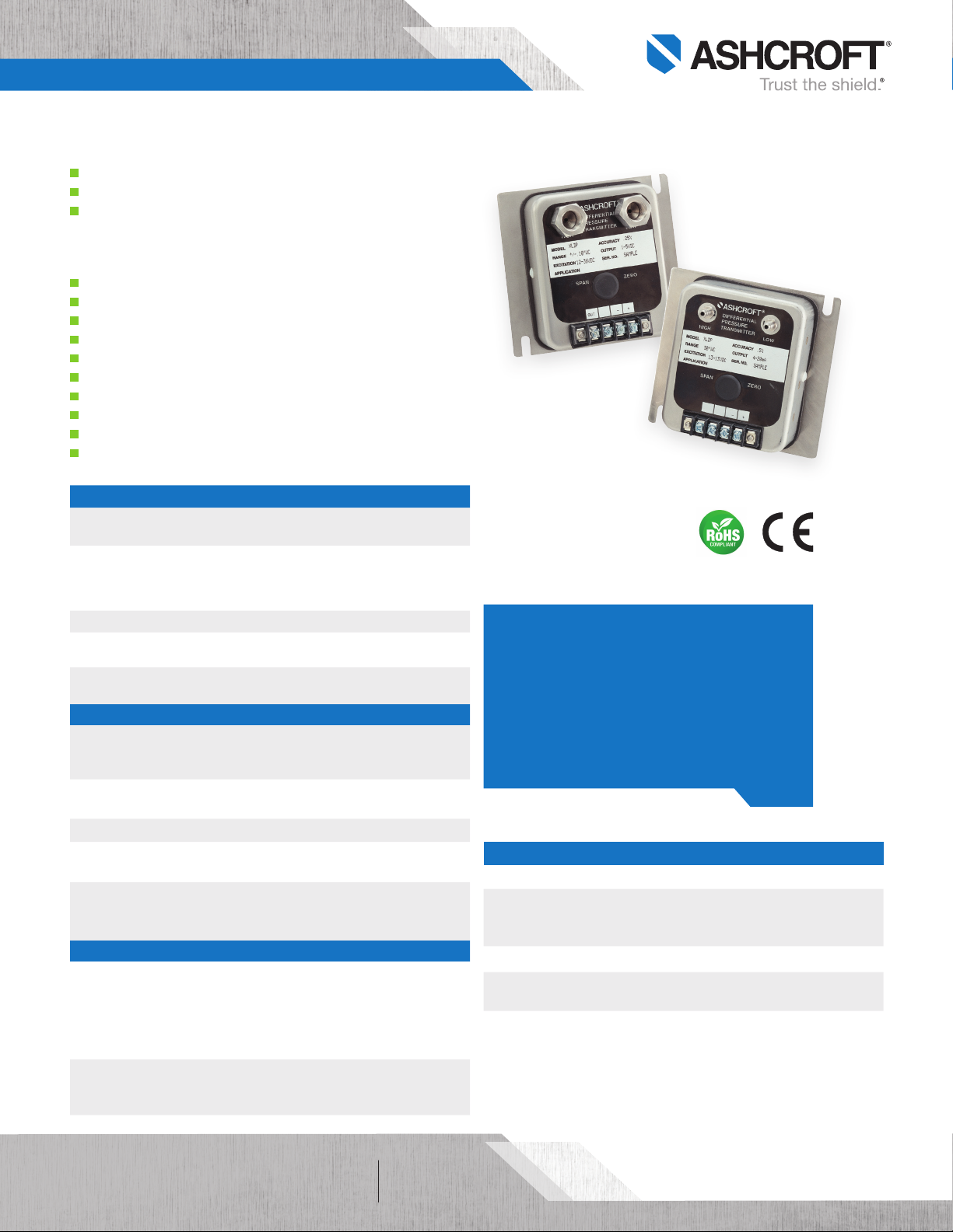
XLdp Ultra-Low Differential Pressure Transmitter
FEATURES
Current and voltage output signals available
Custom ranges available
Si-Glass™ technology enables precise measurement
and control of very low pressures
TYPICAL USES
HVAC/R
Fume Hood Control
Lab/Clean/Hospital Room Pressurization
Medical Lung Function/Breathing Equipment
Fan Tracking
Filter Monitoring
Ultra-Low Velocity Measurements
Leak Detection
Laminar Flow
Building Energy Management/Comfort Control
Systems
PERFORMANCE SPECIFICATIONS
Reference
Temperature:
Accuracy Class: ±0.25% of span, ±0.5% of span
Stability: ±0.25% of span/year at reference conditions
Media Compatibility: Clean, dry and non-corrosive gas
Standard Response
Time:
ENVIRONMENTAL SPECIFICATIONS
Temperature Limits: Storage:
Thermal Coefficients:
Vibration Sweep:
Humidity Effects:
EMC:
FUNCTIONAL SPECIFICATIONS
Mounting Position
Effect:
Max. Static (Line)
Pressure:
25 psi
70°F ±2ºF (21°C ±1ºC)
(Terminal Point Method: includes non-linearity,
hysteresis, non-repeatability, zero offset and span
setting errors)
NOT FOR USE ON LIQUIDS
250ms
–40°F to 180°F (–40°C to 82°C)
Operating:
Compensated:
Zero & Span: ±0.015% of span/°F
(From 70°F (21°C) reference temperature)
<0.05% span/g temporary effect 0-60Hz
No performance effect at 10-95% R.H.
noncondensing
Directive 2004/108/EC
IEC/EN 61326-1: Edition 1.0 Industrial
IEC/EN 61326-2-3: Edition 1.0 Annex BB Industrial
≥0.5 IWC: ±0.1% of span/g
0.25 IWC: ±0.25% of span/g
0.1 IWC: ±0.5% of span/g
Calibrated horizontally (STD.), unless otherwise
specified. Mounting Position Effect easily corrected with
zero potentiometer
Proof:
15 psid
–20°F to 160°F (–29°C to 71°C)
35°F to 135°F (1.7°C to 57°C)
Burst:
25 psid
XLdp
Pressure Transmitter
*See Approvals on page 2 regarding CE
and RoHS certifications.
KEY BENEFITS
• Broad temperature capability
• Superior long-term stability and repeatability
• High overpressure protection
• On board voltage regulation allows use of low
cost unregulated power supply
• 3 year warranty
ELECTRICAL SPECIFICATIONS
Circuit Protection: Reverse Wiring Protected
Potentiometers:
Supply Current: <6 mA for Voltage output
Warm-up Time: 5sec Max. to meet stated specifications from initial
Output Signal: 4-20 mA (2 wire) 12-36 Vdc
Externally accessible, non-interactive
Zero: ±10% of span
Span: ±10% of span
Power-up
1-5 Vdc (3 wire) 12-36 Vdc
1-6 Vdc (3 wire) 12-36 Vdc
Output signal is independent of power supply
changes: 12-36 Vdc range without effect on output
signal
of 41
All speci fications are subject to change without notice.
All sales subject to standard terms and conditions.
©2019 Ashcroft Inc. XLdp_transmit ter_ds1.0, Rev. B, 07/19
ashcroft.com
info@ashcroft.com
1.800.328.8258
Page 2
Data Sheet
XLdp Ultra-Low Differential Pressure Transmitter
PHYSICAL SPECIFICATIONS
Electrical Connection:
Pressure Connections:
Weight:
Environmental Rating:
Screw Termination
¼ barbed Male, ¹⁄8 barbed Male and ¼ NPT Female
14 oz
NEMA 2
WETTED MATERIAL
Media: Clean, dry air/gases compatible with Aluminum,
Titanium, PBT, Buna, Silicon, Glass, Gold, Silicone
Rubber, Silicone RTV and Stainless steel
NOT FOT USE ON LIQUIDS
NON-WETTED MATERIAL
Housing: 300 Series Stainless steel / Lexan
APPROVALS
*Only units with 4-20 mA output and the ‘XCE’ option are CE and ROHS
compliant.
CE Marked: Per DoC
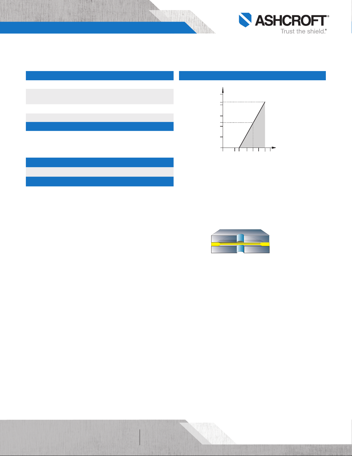
LOAD LIMITATIONS 4-20 mA OUTPUT ONLY
1,250
1,091
1,000
750
545
500
Loop Resistance (Ω)
250
0
0 10 12 20 24 30 36 40
V
= 12V+ (0.022A x RL)
min
R
= RS +R
L
RL = Loop Resistance (ohms)
R
= Sense Resistance (ohms)
S
R
= Wire Resistance (ohms)
W
OPERATING
REGION
Loop Supply Voltage (VDC)
W
Featuring a highly reliable variable capacitance sensor using the patented
Ashcroft® Si-Glass™ sensor. This ultra-thin single crystal diaphragm provides
inherent sensor repeatability and stability.
Sensor Cross Section
The silicon diaphragm sensor has no glues or
other organics to contribute to drift or
mechanical degradation over time
All speci fications are subject to change without notice.
All sales subject to standard terms and conditions.
©2019 Ashcroft Inc. XLdp_transmit ter_ds1.0, Rev. B, 07/19
of 42
ashcroft.com
info@ashcroft.com
1.800.328.8258
Page 3

Data Sheet
XLdp Ultra-Low Differential Pressure Transmitter
ORDERING CODE Example:
Model
XL3 - XLdp Series, ±0.25% of span, ±0.015% of span T.C. /°F XL3
XL5 - XLdp Series, ±0.5% of span, ± 0.015% of span T.C. /°F
Pressure Connection
F02 - ¼ NPT Fem ale F02
MB1 - Board level/No case
MB2 - ¼ Barb ed Male
MB8 - ¹⁄8 Barbed Male
Output Signal
15 - 1-5 Vdc
16 - 1-6 Vdc
42 - 4-20 mA 42
Eletrical Termination
ST - Screw Terminal ST
Pressure Range
Unidirectional Ranges (differential)
P1IW - 0.10 IWD
P25IW - 0.25 IWD
P5IW - 0.50 IWD
P75IW - 0.75 IWD
1IW - 1.00 IWD
1P5IW - 1.50 IWD
2IW - 2.00 IWD 2IW
2P5IW - 2.50 IWD
3IW - 3.00 IWD
5IW - 5.00 IWD
10IW - 10.00 IWD
15IW - 15.00 IWD
25IW - 25.00 IWD
50IW - 50.0 0 IWD
Bi-directional Ranges
P05IWL - ±0.05 IWD
P1IWL - ±0.10 IWD
P25IWL - ±0.25 IWD
P5IWL - ±0.50 IWD
1IWL - ±1.00 IWD
2IWL - ±2.00 IWD
2P5IWL - ±2.50 IWD
3IWL - ±3.00 IWD
5IWL - ±5.00 IWD
10IWL - ±10.00 IWD
25IWL - ±25.00 IWD
50IWL - ±50.00 IWD
Opti on (if i ndicating an option(s) m ust in clud e an “X”) –X__
CE - CE Approval (with 4-20 mA only)
CL - Custom pressure range calibration
NH - SS tag NH
NN - Paper t ag
V9 - Calibrated vertically
X1 - Fast response time
X2 - Slow response time
XL3 F02 42 ST 2IW –XNH
All speci fications are subject to change without notice.
All sales subject to standard terms and conditions.
©2019 Ashcroft Inc. XLdp_transmit ter_ds1.0, Rev. B, 07/19
of 43
ashcroft.com
info@ashcroft.com
1.800.328.8258
Page 4

Data Sheet
XLdp Ultra-Low Differential Pressure Transmitter
DIMENSIONS
For reference only, consult Ashcroft for specific dimensional drawings
4.6
FO2
MB2
F02
1.98
1.29
MB2
1.9
1.3
3.3
1.7
3.9
4.2
All speci fications are subject to change without notice.
All sales subject to standard terms and conditions.
©2019 Ashcroft Inc. XLdp_transmit ter_ds1.0, Rev. B, 07/19
of 44
ashcroft.com
info@ashcroft.com
1.800.328.8258
 Loading...