

Page 1
Installation and Maintenance Instructions for
0.22 (6)
3.32
(84)
3.26 (83)
0.28 (7) X 3 HOLES
4.03 (102)
Ø2 . 3 1( 59)
4 . 61
(1 1 7)
2. 3 1
ACTIVE BUL B
L ENGTH
( 59)
2. 77
( 70)
2. 27
(58)
1
. 25
(3 2)
0.25
(6)
3
.00
(
76 )
Ø0 .37
(9)
“L”
2.50
(64 )
2.00
(51)
3/4 NPT
Ø
0.22
(6)
3.32
(84)
3.26 (83)
Ø 0 .28 (7) X 3 HOLES
4. 03 ( 102 )
Ø2 .3 1(59)
4.6 1
(
117)
2.77
( 70 )
2. 2 7
( 58)
1. 2 5
( 3 2 )
0. 2 5
(6 )
Ø0 . 37
( 9)
2. 0 0
( 51)
1. 3 1
( 3 3 )
2.3 1
ACTIVE BULB
LENGTH
(59)
“S”
3/4 NPT
1/2 NPT MALE
7/8 HEX
5.20
(132)
3.61
(92)
2.18
(55)
0.32
(8)
4.37
(
111)
1.37
(35)
Ø0 .2 8x3 HOLES
(7)
2 . 3 1
( 59)
5.2 3
( 13 3 )
1. 93
( 49)
2. 31
ACTIVE BULB
LENGTH
( 59)
Ø3. 90
(99)
0.03
(
1)
3. 58
(91)
0.31 ( 8 )
1. 2 2( 3 1)
2.50
(64)
“L”
3
.00
(76)
Ø0 .37
(9)
3/4 NPT 2 HOLES
5.20
(132)
3.60 (91)
2.18
(55)
4.37
(111)
1.37
(35)
Ø0 .28 x 3 HOLES
(7)
1.93
(49)
0
.3 2
(8)
5. 23
(13 3)
2.3 1
(59)
Ø3 .90
(99)
0.0 3
(
1)
3.58
(91)
0.31
(8)
1.2 2
(3 1)
0.3 7
(9)
2.31
A
CTIVE BULB
(59)
1.3 1
(33 )
“
S”
1/2 NPT MALE
3/4 NPT 2 HOLES
7/8 HEX
LENGTH
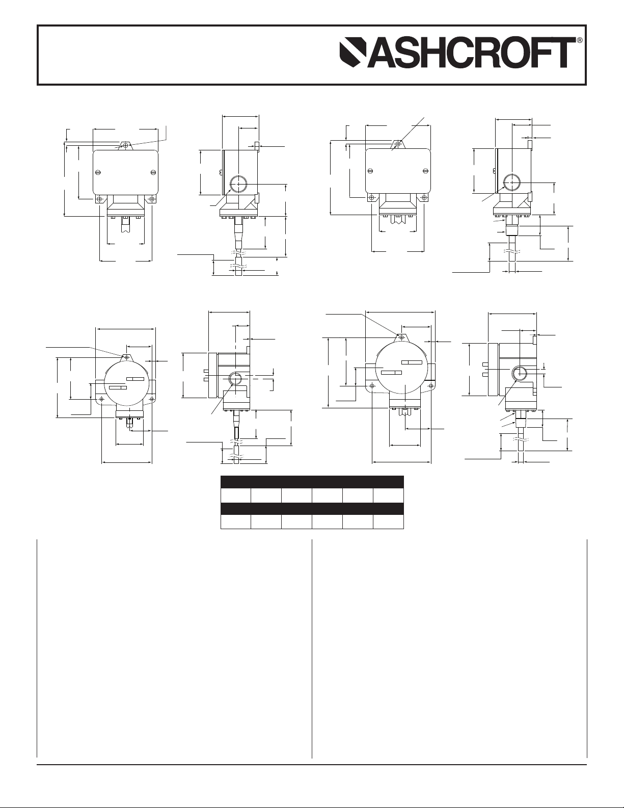
T400 & T700 ASHCROFT®Snap Action
Switches for Temperature Control
400 REMOTE MOUNT T400 DIRECT MOUNT
T
3.5 lbs.
700 REMOTE MOUNT T700 DIRECT MOUNT
T
4.5 lbs.
2.5 lbs.
3.7 lbs.
STEM LENGTH – INCHES
S
2.75 4.0 6.0 9.0 12.0
LINE LENGTH – FEET
5.0 10.0 15.0 20.0 25.0
L
INTRODUCTION
The Ashcroft®temperature switch is a precision built U.L. and
C.S.A.approved control device which features a mechanical
snap action switch.Controllers are available for operation on
ature with fixed or v
temper
types are a
vailable for operation on increasing or decreasing
ariable differential.Also, manual reset
temperature.The manual reset types remain tripped until reset
The standard
.
enclo
y pressing a b
b
electrical switch is SPDT and is available with various electrical
characteristics.Two SPDT switch elements mounted together
are available except on variable deadband and manual reset
types. Bulb material is stainless steel.
The Ashcroft snap action temperature switch is furnished in the
standard NEMA 4/4X and e
sure styles.Both enclosures are epoxy coated aluminum castings.
ALLA
INST
These controls are precision instruments and should never be
left with internal components exposed. During installation insure
that covers are in place and conduit openings are closed except
when actually working on the control. Good piping practice
© 2007 Ashcroft Inc., 250 East Main Street, Stratford, CT 06614-5145, USA, Tel: 203-378-8281, Fax:203-385-0499, www.ashcroft.com
All sales subject to standard ter
utton on the top of the enclosure
TION
ms and conditions of sale
xplosion proof NEMA 7 and 9
I&M009-10006-10/00 (250-2230G) AMR 12/07
.
requires the use of a thermowell for installation where pressure
may be applied to the thermal system.The thermowell provides
protection against physical damage as well as corrosive effects
Use of a ther
of media flow
ulb from the process line without disturbing the process.
b
.
Standard thermowell materials include brass, steel and stainless
other mater
steel;
should be based on corrosion resistance requirements and
process pressure.
MOUNTING T400 AND T700 SERIES
There are three holes external to the enclosure for surface
mounting.
-
dimension drawing.
A.
Location of these holes is sho
Direct - Mounted Contr
These controls ha
attached directly or indirectly by means of a thermowell to
equipment to be controlled.
trol always use the wrench flats or hex above the threads.
Do not twist the housing.
mowell also facilitates removal of the
ailable upon request.
ials are a
v
wn on the general
ols
1
e a
v
⁄
2 NPT threaded adapter and ma
When installing or removing con-
Selection
y be
Page 2

Installation and Maintenance Instructions for
TERMINAL BLOCK
FRONT SWITCH
TERMINAL BLOCK
REAR SWITCH
N
C
N
O
C
N
C
NO
C
T400 & T700 ASHCROFT®Snap Action
Switches for Temperature Control
. Remote Mounted Controls
B
wo types of union bushings are available to install a remote
T
ounted bulb into a thermowell or other
m
A non-pressure tight type consists of a bushing, split grommet
and compression nut.To use this, the bulb is inser ted through
the nut and the split grommet is slipped into the capillary
between the compression nut and the bushing.After positioning
the bulb as desired tighten the nut to the bushing.This will lock
the capillary at the desired location. The pressure tight type is
lamped to the bulb after insertion by tightening the compres-
c
ion nut.To use this, the union bushing is screwed into the
s
PT threaded hole.The compression nut and sleeve are slipped
N
onto the bulb which is then inserted into the union bushing.
The bulb is then positioned and the compression nut is hand
tightened pus 2
1
⁄
4 turns. This will lock the capillary at the
desired location.
ELECTRICAL CONNECTIONS
Remove cover
T400 Series – two screws hold cover to enclosure
T700 Series – cover unscrews
1
PT threaded hole.
⁄
2 N
1
⁄
2
When hermetically sealed switch element (s) are supplied, the
lead color coding is as follows:
Common – White
Normally Closed – Red
Normally Open – Blue
T700 SERIES
PDT
S
equirements.
r
2-SPDT – Wire to front switch terminal block (left) and rear
switch terminal block (right) as marked.Strip insulation
Wire directly to the switch according to circuit
–
5
⁄
16˝,
insert in proper terminal connector and tighten clamping screw
to secure.
ADJUSTMENT OF SETPOINT
T400 & T700 Series – A single setpoint adjustment nut (7⁄
8˝) is
located centrally at the bottom on the inside of the enclosure.
The bulb of the control should be immersed in a bath at the
desired setpoint temperature.Optimum performance will be
obtained if the bulb is fully immersed. Allow five minutes for
initial stabilization.
As received, the temperature switch will normally be set to
approximately 90% of the indicated range.After stabilization,
turn the adjustment nut until switch changes mode.Direction of
turning is indicated on a label affixed to the inside of the control
enclosure.When setpoint has been achieved raise and lower
temperature to insure that the setpoint is correct.
After installation of the control replace cover to insure electrical
safety and to protect internal parts from the environment.
CONDUIT CONNECTIONS
Note
– It is recommended that Teflon®tape or other sealant be
used on conduit, bushing or plug threads to ensure integrity of
the enclosure.
T400 Series standard – one 3⁄
T700 Series standard – two 3⁄
4 NPT conduit hole right side.
4 NPT conduit holes with one per-
manent plug. NEMA 7 & 9 enclosures require proper conduit
seals and breathers as per the National Electrical Code.
T400 & T700 series – XJL variation – 3⁄
ushing supplied.
b
T400 Series – XJK v
ariation – two
3
⁄
1
4 to
⁄
2 NPT reducing
4 NPT conduit holes
.
T400 SERIES
SPDT
– Wire directly to the switch according to circuit requirements. On controls with pilot lights wire lights according to circuit
diagram on inside of cover. See special wir ing instr uction tag for
single switches with two pilot lights and dual switches with one
or more lights.
2-SPDT – Dual switching elements consist of two SPDT switches
mounted together in a bracket.Switches are calibrated to have
ultaneous oper
sim
ation within 1% of r
ange either on increasing
or decreasing pressure but not in both directions.Wire directly to
the front and rear switch according to circuit requirements.
Leads are provided on rear switch color coded as follows:
Common – White
Normally Closed – Red
mally Open
Nor
– Blue
T450 and T750 VARIABLE DEADBAND SWITCHES
Deadband is varied by rotating the wheel on the precision
switch.When viewed from the front of the enclosure, rotation to
the left increases deadband – rotation to the right decreased
deadband. Letters on the wheel may be used as a reference.
Deadbands obtainable will vary from 0.5% to 9% of pressure
range depending on range segment and type of diaphragm.
ADJUSTMENT OF SETPOINT
As received, the temperature switch will normally be set to
approximately 90% of range.Rotate the wheel on the MICRO
SWITCH all the way to the right; this will provide smallest dead-
Increase bath temperature to the required setpoint and
band.
n the adjustment n
tur
ut until the s
witch changes mode. Lower
the bath temperature to reset the switch.Rotate the wheel on
the MICRO SWITCH until the desired deadband is obtained.
The upper setpoint will be changing upward with this adjustment. Lower the bath temperature to reset the switch. Raise the
bath temper
ature to the desired setpoint and turn the adjusting
nut until the switch changes mode.Lower the bath temperature
and check reset point and deadband.
T428 &
T429 MANU
AL RESET SWITCHES
Dress wire leads from switch terminals so as not to interfere
with or touch reset button.
Note – As indicated above, adjustment of setpoint is made by
7
use of
⁄
8˝ nut. Precision switch element mounting screws and
acket adjusting screw are factor y sealed and should not be
br
tampered with.
© 2007 Ashcroft Inc., 250 East Main Street, Stratford, CT 06614-5145, USA, Tel: 203-378-8281, Fax:203-385-0499, www.ashcroft.com
All sales subject to standard ter
ms and conditions of sale
I&M009-10006-10/00 (250-2230G) AMR 12/07
.
 Loading...