

Page 1
Installation and Maintenance
Instruction Manual
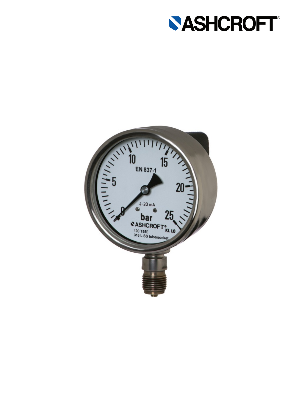
Process gauge with integrated transmitter, model T5500E
IM-T5500E-E-Rev 0 08/2014 Page 1 of 10
P/N 095I105-01EN-Inc
Page 2

Table of contents:
General remarks ......................................................................................................................................................... 3
1
1.1 Purpose of this Manual ........................................................................................................................................ 3
1.2 Symbols ............................................................................................................................................................... 3
1.3 Limits of liability ................................................................................................................................................... 3
1.4 Copyright ............................................................................................................................................................. 3
1.5 Warranty .............................................................................................................................................................. 3
1.6 Manufacturer’s address, customer services........................................................................................................ 3
2 Safety .......................................................................................................................................................................... 4
2.1 General sources of hazards ................................................................................................................................ 4
2.2 Use in accordance with intended purpose .......................................................................................................... 4
2.3 Operator’s responsibility ...................................................................................................................................... 4
2.4 Staff qualifications (target group assessment) .................................................................................................... 5
2.5 Signs/Safety markings ......................................................................................................................................... 5
2.6 Safety equipment ................................................................................................................................................ 5
2.7 Environmental protection..................................................................................................................................... 5
3 Technical data ............................................................................................................................................................ 5
4 Labeling on the device ................................................................................................................................................ 5
5 Construction and function ........................................................................................................................................... 6
5.1 Overview.............................................................................................................................................................. 6
5.2 Description of function ......................................................................................................................................... 6
5.3 Description of components .................................................................................................................................. 6
5.4 Accessories ......................................................................................................................................................... 6
6 Transport .................................................................................................................................................................... 7
6.1 Safety .................................................................................................................................................................. 7
6.2 Transport inspection ............................................................................................................................................ 7
6.3 Storage ................................................................................................................................................................ 7
7 Assembly/Installation .................................................................................................................................................. 7
7.1 Safety .................................................................................................................................................................. 7
7.2 Preparations (requirements for the installation location) ..................................................................................... 7
7.3 Mounting/Installation ........................................................................................................................................... 7
7.4 Starting up ........................................................................................................................................................... 8
7.5 Subsequent relocation of the gauge (by the customer) ...................................................................................... 9
8 Servicing ..................................................................................................................................................................... 9
8.1 Safety .................................................................................................................................................................. 9
8.2 Check on function, and recalibration ................................................................................................................... 9
8.3 Cleaning and maintenance ............................................................................................................................... 10
9 Faults ........................................................................................................................................................................ 10
9.1 Safety ................................................................................................................................................................ 10
9.2 Conduct in the event of faults ............................................................................................................................ 10
9.3 Fault table .......................................................................................................................................................... 10
9.4 Conduct following fault rectification ................................................................................................................... 10
10 Removal, disposal ................................................................................................................................................. 10
10.1 Safety ............................................................................................................................................................. 10
Page 2 of 10
Page 3
10.2
Removal ......................................................................................................................................................... 10
10.3 Disposal ......................................................................................................................................................... 10
11 Appendix ............................................................................................................................................................... 10
11.1 Data sheet for Bourdon tube pressure gauge with integrated transmitter T5500E ....................................... 10
1 General remarks
1.1 Purpose of this Manual
This Operating Manua l contains fundamental and essential adv ice to be followed for the installation, o peration and
servicing of the device. It must be read without fail before assembly and start-up of the device by the fitter, the
operator and the speci alist pers onnel res pons ible f or the d evice. T his O peratin g Manu al m ust be a vailab le a t the po int
of use at all times.
The following sections about general safety information (2) and also the following specific advice regarding the
intended purposes ( 2.2) an d thr o ugh to d is posa l ( 10.3) contain im por tant s af ety information whic h, if not f oll o wed, may
result in risks for people and animals, or to property and buildings.
1.2 Symbols
Warning!
This indicates a poss ibl y hazard ous sit uation wher e failin g to f ollow a dvice m a y result in risk s to peo ple,
animals, the environment and buildings.
Information!
This emphasizes key information for efficient, fault-free operation.
1.3 Limits of liability
Failure to respect this safety information, the envisaged uses or the limit values relating to use indicated in the
technical data for the device may result in risk or to injury to people, the environment or the plant.
Claims for compensation for damage against the device supplier are excluded in such an eventuality.
1.4 Copyright
This Operating Man ual m ay only be co pied and pass ed on as a c omplete docum ent without t he spec ial perm ission of
the publisher.
1.5 Warranty
For the product described here, we offer a warranty pursuant to Section 6 Gu arantee in Respect of Defects in our
General Terms and Conditions of Delivery and Payment.
1.6 Manufacturer’s address, customer services
Ashcroft Inc.
250 East Main Street
Stratford, CT 06614
Ph#: (800) 328-8258
Website: www.ashcroft.com
Page 3 of 10
Page 4

2 Safety
2.1 General sources of hazards
Pressure gauges are pressurized instruments where failure can result in hazardous situations. The selection of
pressure gauge should be made in accordance with the rules set out in EN 837-2. A failure resulting in injury or
damage may be caus ed by excessive overpr essure, excessive vibr ation or pressure pulsat ion, excessive ins trument
temperature, corrosion of the pressure contai ning parts, or other mis use. Consult the manuf acturer before installing if
there are any questions or concerns.
2.1.1 Overpressure
Pressure spikes in excess of the rated overpressure capability of the transducer may cause irreversible electrical
and/or mechanical damage to the pressure measuring and containing elements.
Fluid hammer and surges can destr oy any pressure transducer an d must always be avoided. A pr essure snubber
should be installed to elim inate the damaging hammer effects. Fluid ham mer occurs when a liquid flow is sud
stopped, as with quick closing solenoi d valves. Sur ges occ ur when flow is sud denly begu n, as when a pum p is turned
on at full power or a valve is quickly opened.
Liquid surges are particularly dam aging to pressure transducers if the pipe is original ly empty. To avoid damaging
surges, fluid lines shou ld remain full (if possible), pum ps should be brought up to power slo wly, and valves opened
slowly. To avoid damage from both fluid hammer and surges, a surge chamber should be installed.
Symptoms of fluid hammer and surge's damaging effects:
• Pressure transducer exhibits an output at zero pressure (large zero offset).
• Pressure transducer output remains constant regardless of pressure
• In severe cases, there will be no output.
denly
2.1.2 Freezing
Prohibit freezing of media in pressure port. Unit should be drained (mount in vertical position to prevent possible
overpressure damage from frozen media.
2.1.3 Static electrical char ges
Any electrical device m ay be susceptible to dam age when exposed to static electrical charges. To avoid damage to
the transducer observe the following:
• Operator/installer should follow the proper ESD (electrostatic discharge) protection procedures before
handling the pressure transducer components.
• Ground the body of the device BEFORE making any electrical connections
• When disconnecting, remove the ground LAST!
The shield and drain wire in the cable (if supplied) is not connected to the transducer body, and is not a
suitable ground.
2.2 Use in accordance with intended purpose
The devices are only to be used for the intended purpose as described by the manufacturer.
The devices are used for direct display of overpressures, vac uum and compound pressure and for tr ansmission of
overpressures, vacuum and compound pressure into a standard electrical output signal.
For each use scenario, the corresponding set-up regulations must be respected.
The usage in explosion risk areas is not allowed.
2.3 Operator’s responsibility
Safety instructions for proper oper ation of the device must be resp ected. They are to be provided by the operator for
use by the respecti ve personnel for installation, servic ing, inspection and op eration. Risk s from electrical ener gy and
from the released ener gy of the medium, fr om escaping media and fr om improper connection of the device must be
eliminated. The details f or this are to be found in the corresponding appl icable set of regulations, such as DIN EN ,
UVV (accident prevention regulations) and in sector-specific instances of use (DVWG, Ex-. GL, etc.) the VDE
guidelines and the regulations supplied by local utilities companies.
The device must be taken out of service and secured against inad vertently being res tarted, if the presumption is t hat
risk-free operation is no longer possible (see Chapter 9: Faults).
Page 4 of 10
Page 5

Field Modification or other altera tions to the instrument are not permitted and will void the warr anty. This also app lies
to installation of spare parts. Possible conversations or alterations may only be carried out by the manufacturer.
The operational safet y of the device is only guarant eed where it is used for its intended purpose. The specification of
the device must be adapted to the m edium used in the plant. T he limit values indicated in th e technical data m ust not
be exceeded.
The safety information det ailed in t his Operating Manual, ex isting nati onal regula tions for accident prevent ion, and the
operator’s internal regulations regarding working, operations and safety must be respected.
The operator is res ponsible for all spec if i ed servicing, inspectio n and i nst allat ion works being carr i ed out by authorized
and qualified specialists.
2.4 Staff qualifications (target group assessment)
The device may onl y be installed and started up by spec ialist staff f amiliar with installat ion, start-up and oper ation of
the product.
Specialist staff is defined as thos e individuals capable of assessing the work assign ed to them on the basis of their
specialist training, knowledge and experience of the relevant standards, and can identify possible risks.
2.5 Signs/Safety markings
The pressure gauge and packaging carry markings detailing the article number, measurement range and
manufacturer. The pressure gauge can be provided with additional signs and safety markings advising on special
conditions:
Advice on calibration
Safety marking pursuant to EN 837-1
Oil-can deleted (if used for oxygen service)
Silicone-free (for use in the automotive industry)
2.6 Safety equipment
The window of model T5500E uses multi-layer safety glass.
This device has internal transient and reverse power protection.
2.7 Environmental protection
This device does not contain any environmental critical components.
3 Technical data
The detailed technical information can be found in the documents in the Appendix, Chapter 11.
4 Labeling on the device
The label with the s erial n um ber and t ype des ignat ion is locat ed on t he outs ide of the housing. T he m aterials ide ntifier
is encoded in the type designation.
Page 5 of 10
Page 6

1 Socket and instrument connection
5 Construction and function
5.1 Overview
2 Electrical termination
3 Dial
4 Pointer
5 Cap with access to PCB
6 Vent valve
7 Case
8 Bayonet ring
5.2 Description of function
The sensing element, a bo urdon tube ( C-form or helical) that is welded to the s ocket, will be exposed f rom ins ide with
pressure. Under pres sure the elast ic tube is deflec ting against the zero position. This deflection is proportio nal to the
adjacent pressure. The movement transfers the deflection to the pointer.
The display of the measured value is provided on a 270° scale (dial arc).
The sensing element, a thin film pressure sensor that is welded to the socket, will be exposed from outside with
pressure. Under press ure the e lastic diaphragm is deflecting against the zero pos ition. T his def lection is m easured b y
resistors of a Wheatstone bridge located at the back side of diaphr agm. The PCB transfers the output s ignal of the
sensing element into a standard electric output signal.
5.3 Description of components
5.3.1 Scale with pointer
The pressure gauge is equipped with a dial face and pointer pursuant to EN 837-1, nominal size 100 mm (4”).
Erläuterung , zusätzli ch ein Hin weis:
5.3.2 Instrument connection
The instrument connection is located on the bottom side of the pressure gauge and is a ¼” or ½” Male NPT threaded
pressure connection.
5.3.3 Vent val ve
The vent valve for the housing is l ocated on the top side. If the nipple is pu lled out, the hous ing is venti lated and the
pressure which has built up in the housing due to the influence of temperature is discharg ed. With the valve closed ,
protection class IP 65 is achieved.
5.3.4 Thin film sensing element
The pressure transm itter in corporates polysilicon th in film tec hnology. Modern low-pr essur e chem ical vapor d eposit ion
methods provide sim ple, stable molecular bonds between the metal diaphr agm and a polysilicon strain gage bridge.
There are no epoxies or bonding agents to con tribute to sig nal instability or drift. The integral metal diaph ragm and
polysilicon bridge are virtually unaffected by shock, vibration or mounting.
5.3.5 Printed circuit board
The PCB provides the signal conditioning and is equipped with pots for zero and span adjustment.
5.3.6 Electrical termination
The electrical termination is provided with standardized termination plug.
5.4 Accessories
Please contact the manufacturer regarding special tools and accessories.
Page 6 of 10
Page 7

6 Transport
6.1 Safety
The pressure gauge should be protected against the effects of knocks and impacts. The device should only be
transported in the pack aging provided to prevent dam age. The device s hould only be tr ansported in a cl ean condition
(free of residues of measuring media).
6.2 Transport inspection
Delivery should be check ed for completeness and potential damage due to transport. In the event damage, delivery
must not be accepted, or only accepted subject to reservation of the scope of the damage being recorded.
6.3 Storage
The pressure gauge must be st ored in dry, clean c onditions, within a tem perature range of -40/185 °F (-40/+85 °C),
protected against direct exposure to sunlight and protected against impact damage.
7 Assembly/Installation
7.1 Safety
To ensure safe working during installat ion an d s erv icin g, s uit ab le sh ut -off valves must be i ns tal le d in the plant (see 5.4
Accessories) prior to enabling the device:
Relieve pressure to remove from operation;
Disconnect power for repair or inspection within the relevant plant;
Or to enable function tests of the device to be performed “on site”.
During preparation to mount/install the gauge, the plant must be protected against being switched back on.
7.2 Preparations (requirements for the installation location)
A check on suitabilit y of the device for the medium to be measured, the sc ope of the m easurement range and of
the protection against special conditions such as vibrations, pulsations and pressure spikes.
A bracket must be installe d to support the pressure gauge if the metering pipe is not able to provide adequate
support.
The installation location should be selected wher e no pers onn el oper at e beh ind the rear of the pressure gauge.
7.3 Mounting/Installation
7.3.1 Process connection
As standard, the device is equ ipped to be pipe mounted with a pressure connect ion shank pursuant to DIN EN 837-1.
The device is calibrated ex-works for vertical installation.
Connection to be undertaken by authorized and qualified specialist staff only.
Use only with the m echanical process connec tion provided – re garding the configuration, see order co de on the
device type label, with a matching threaded seal.
When connecting the device, the pipes must be depressurized.
The pressure metering pipe must be laid inclined in suc h a way that, for example, f or measurements of fluids no
air pockets can f orm, and for measurem ents of gases no water pock ets. If the necessar y incline is not achieved,
then at suitable points water separators or air separators must be installed.
The pressure metering pipe must be kept as short as possible and laid without sharp bends, to avoid the
occurrence of irritating delays.
With liquid measurement media, the pressurized connection pipe must be degassed, since any gas bubble
inclusions result in measurement error.
If water is used as the measurement medium, the device must be frost-protected.
Page 7 of 10
Page 8

Safety notice: Only mount using the correct ope n-jawed wrench, and do not twist the device itself.
G ¼ B, G ½ B
1. Pressure connection
2. Gasket DIN 16258
Other parallel threads
1. Pressure connection
2. Gasket (USIT)
7.3.2 Electrical connectio n
Connection to be undertaken by authorized and qualified specialist staff only.
The electrical connect ion of the de vice is to be u nderta k en in ac cor dance w ith t he rele vant reg ulati ons of the VDE
and the regulations supplied by the local utilities company.
Disconnect the plant from the mains supply before wiring electrical connections.
Power supply to be provided is 12-30 VDC
Maximum loop resistance for 4 ... 20 mA: ≤ (UB – 9,5 V) / 0,02 A
For minimum noise sus ceptibility, avoid running the trans ducer’s cable in a conduit that contains high current AC
power cables. Where possible avoid running the cable near inductive equipment.
Units with shie lded cable electr ical t ermination, connec t the drai n w ire to the gu ar d ter minal on the read out d ev ice
or measuring instrum ent, if available. In all other cases connec t to the ground or to the power supply ne gative
terminal.
Wiring Diagrams:
7.4 Starting up
The precondition f or start-up is proper installation of a ll electrical feed l ines and m etering pipes. All con necting lines
must be laid such that no mechanical forces can act on the device.
Before start-up, the seal on the pressurized connection line must be checked.
7.4.1 Zero point adjustment for pressure gauge
The pressure gauges are supp lied calibrated ex-wor ks, so that as a rule there is no need for calibration works at the
installation point.
For devices with Micrometer pointer (see. order code), zero point adjustment on site is possible. For this, proceed as
follows:
Page 8 of 10
Page 9

Depressurize the pressure metering pipe.
Open the bayonet ring and remove ring and window.
Hold the pointer in place while turning the screw, until the
pointer (after releasing again) has the correct position.
Close the case again and pay attention to correct fit of
window, gasket and bayonet ring.
7.4.2 Zero point adjustment for transmitter
While Zero adjustm ent is not normally neces sary, it may be desira ble to trim out an y offset in the system. Ho wever,
proper Span calibration requires a pressure standard three to five times more accurate than the accuracy of the
transducer, and there m ay also be interaction of Span on Zer o. For detailed instr uction see chapter 8.2.1. Zero and
span adjustment for transmitter
7.5 Subsequent relocation of the gauge (by the customer)
Recommendation: D o not remove the pressure gauge from one metering po int a n d f it it in a dif f erent plac e ,
as there is a risk of the measuring media being mixed, with unforeseeable chemical reactions.
8 Servicing
The device is maintenance-free. However, to ensure reliable operation and a long life, we recommend that it is
checked periodically.
8.1 Safety
When undertaking service work on the device, the pressure lines must be depressurized and the plant secured against
being switched on again.
8.2 Check on function, and recalibration
Inspection of function and recalibration should be out at regular intervals. The precise testing cycles should be
adjusted in line with the operating conditions and ambient conditions. In the event of various device components
interacting, the operating instructions for all other devices should also be taken into account.
Check display.
Check function, in conjunction with downstream components.
Check pressurized connection pipes for seal condition.
8.2.1 Zero and span adjustment for transmitter
While Zero adjustm ent is not normally necessary, it may be desirab le to trim out any offset in
the system. However, prop er Span calibration re quires a pressure s tandard three to five tim es
more accurate than th e accurac y of the transducer, and there ma y also be interac tion of Span
on Zero.
Access to “Z” and “S” pots via the e lectrical terminati on or screw cap at the back of the unit is
standard. Access is gained by removing the black threaded cap , once removed you will see th e
pots indicated by “Z” and “S” res pectivel y as sho wn below. U sing a small tr im pot too l, you can
adjust zero ±10% of full scale and span ±10% of full scale.
Recalibration Instructions:
1. Apply 0% full scale pressure.
2. Adjust the output using the zero adjust trim pot.
3. Apply 100% full scale pressure.
4. Adjust the output using the span adjustment trim pot.
5. Repeat steps 1 through 4 as necessary.
Page 9 of 10
Page 10

Model
Description
Document
T5500E
Stainless steel pressure gauge with integrated transmitter model
T5500E
G1.T5500E
8.3 Cleaning and maintenance
Use a non-aggr essive cleaning agent when cleaning; ventilation valve should be clos ed and in accordance with the
protection category of the device.
9 Faults
9.1 Safety
Defective or faulty pressur e gauges pu t the o per at ion al s af ety and process safety of the plant at r isk, and can lead to a
risk or injury to persons, the environment or the plant.
9.2 Conduct in the event of faults
All defective of faulty devices must be taken out of service. If a repair is required, the device must be sent directly to
our Repairs Department. We request that all returns of devices are agreed with our Service Department.
9.3 Fault table
Possible situations indicating a fault:
Jerky or random movement of the pointer
Pointer does not set to zero for pressure less display
Indications that the measurement system seal is
imperfect (discoloration of dial display)
Replacement of the pressure gauge is required in the event any of the above exist .
Bent or loose pointer
Cracked window
Damage to housing or electrical termination
No or wrong output signal, Zero offset
9.4 Conduct following fault rectification
See Chapter 7.3 Mounting/Installation
10 Removal, disposal
10.1 Safety
Residue from process media either within or on uninstalled gauges can constitute a risk to people, the
environment and equi pment. Ad equate prec autionar y meas ures must be adopted. If nec essar y, the devices
must be cleaned thoroughly (see advice in safety data sheets).
10.2 Removal
When undertaking ser vicing of the dev ice, the pressure lines m ust be depressurized, the electrica l connections
isolated from the main supply, and the plant secured against being switched on again.
Take care to uninstall the gauge using a suitable tool.
10.3 Disposal
Please help protect the environment by disposing or recycling the in accordance with the applicable
regulations.
11 Appendix
11.1 Data sheet for Bour don tube pressure gauge with integrated transmitter T5500E
Detailed data sheet is available from supplier’s website (see 1.6 Manufacturer’s address, customer services)
This table refers to specific documents:
Page 10 of 10
 Loading...