

Page 1
3 (A)
2 (C)
1 (B)
3
2
1
2 ELECTRICAL TERMINATIONS AND WIRING
1.76
Wire
Length
.95
(45)
(24)
1.06
(27)
Connection - PIN
1
2
3
V out
Vs
-
Vs
+
Pin 1
Pin 2
Pin 3
Pin 4
KEY
G
2 ELECTRICAL TERMINATIONS AND WIRING
G
2 ELECTRICAL TERMINATIONS AND WIRING
T
EUTSCH DT SERIES DT04-3P
D
Pin Voltage 4-20mA Mating
o. Output Output* Cable Color
N
1 (B) Common V – Black
(C) Output V
2
(A) V + V
3
* Use either V- termination on G2 with
4-20mA output
DEUTSCH DTM SERIES DTM04-3P
Pin Voltage 4-20mA Mating
No. Output Output* Cable Color
1 V + V + Red
2 Common V – Black
3 Output V – White
* Use either V- termination on G2 with
4-20mA output
SHIELDED CABLE, PVC JACKET,
24AWG LEADS
Wire Voltage 4-20mA
Color Output Output*
Red V + V +
Black Common V –
White Output V –
Bare** Shield Shield
* Use either V- termination on G2 with 4-20mA output
M12 ELECTRICAL TERMINATION
FOR G2 (EW), (EO), (E2), (E1)
Mates to optional Hirschmann connector
Part 933 172-100 or equal
Pin Voltage 4-20mA Mating
No. Output Output* Cable Color
1 V + V + Red
2 Case Grd. Case Grd. Green
3 Common V – Black
4 Output V – White
Drain Wire Drain Wire
IP67 Ingress rating
IP67 Ingress rating
– W
+ R
hite
ed
LYING LEADS 18AWG
F
ire Voltage 4-20mA
W
olor Output Output*
C
ed V + V +
R
BlackCommon V – V –
White Output
DIN 43650 FORM C (EN 175301-803-C)
ELECTRICAL TERMINATION
(DC), (N1), (N2), (N3), (N9)
ates to Hirschmann P/N: GSSNR 300,
M
Ashcroft P/N 300A126-01
Pin Voltage 4-20mA Mating
No. Output Output* Cable Color
1 V + V + Red
2 Common V – Black
3 Output White
P67 Ingress rating
I
IP65 Ingress rating
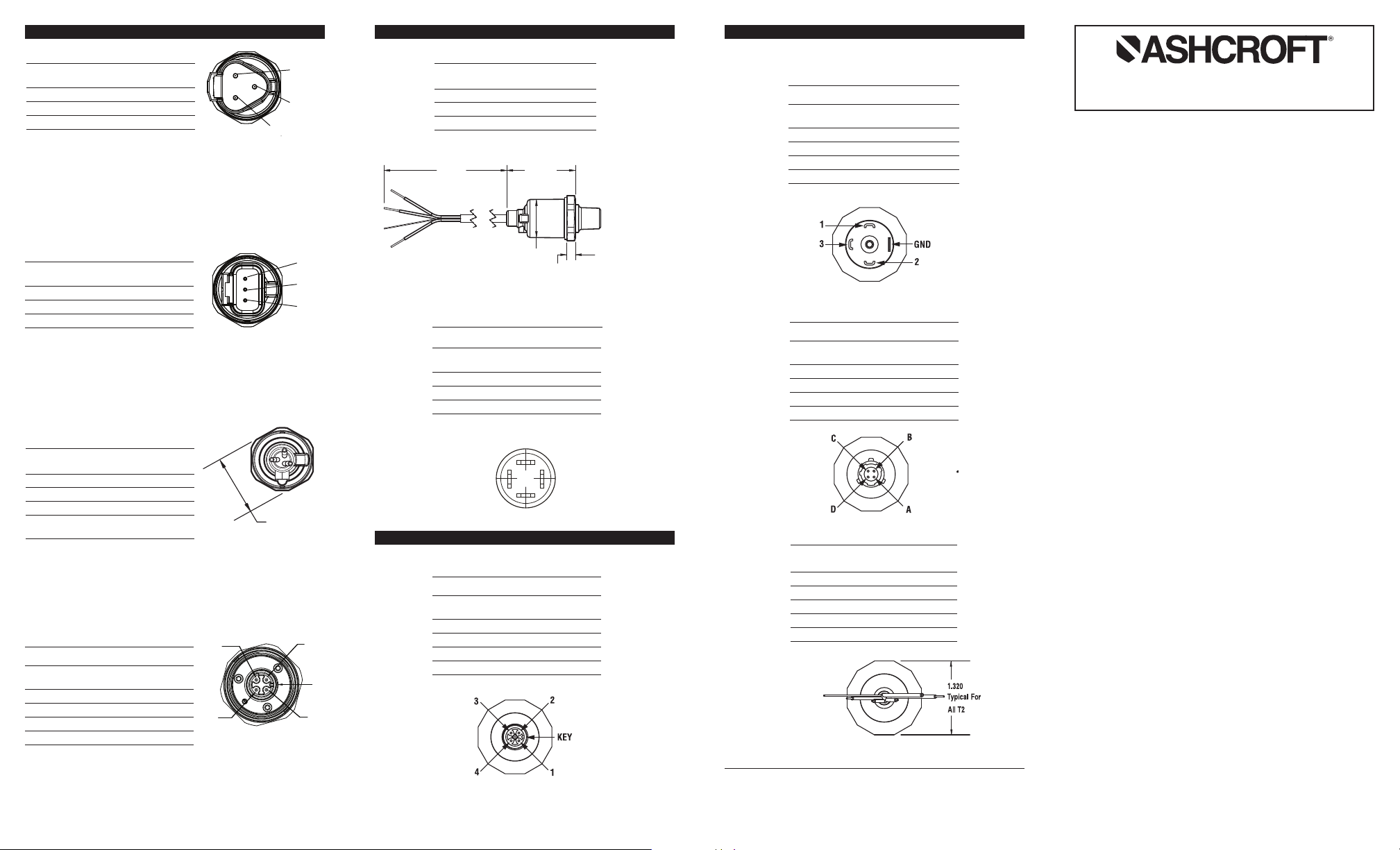
T2 ELECTRICAL TERMINATIONS AND WIRING
M12 ELECTRICAL TERMINATION
FOR T2 (EW), (EO), (E2), (E1)
Mates to optional Hirschmann connector
Part 933 172-100 or equal
Pin Voltage 4-20mA Mating
No. Output Output* Cable Color
1 V + V + Red
2 Output None White
3 Case Gnd. Case Gnd. Green
4 Common Common Black
IP65 Ingress rating
IN 43650 FORM A (EN 175301-803-A)
D
ELECTRICAL TERMINATION
DN), (DO), (D2), (D1)
(
Mates to optional Hirschmann connector
GDM 3009 or equal
Pin Voltage 4-20mA Mating
No. Output Output* Cable Color
1 V + V + Red
Common Common Black
2
3 Output None White
GND Case Gnd. Case Gnd. Green
4-PIN BENDIX STYLE ELECTRICAL
TERMINATION (B4), (H1), (L1), (P2)
Mates to optional Amphenol Bendix connector PTO6A-8-
-SR or equal
4
Pin Voltage 4-20mA Mating
No. Output Output* Cable Color
A V + V + Red
B Output None White
C Case Gnd. Case Gnd. Green
D Common Common Black
SHIELDED CABLE, PVC JACKET, 24
AWG LEADS, TERMINATION (F2), (P1)
Bare** Drain Wire Drain Wire
** Where shielded wiring is being used; Connect the drain wire to the guard
terminal on the read out device or measuring instrument if available. In all
other cases connect to the ground of the power supply negative terminal.
© 2011 Ashcroft Inc., 250 East Main Street, Stratford, CT 06614 USA,
Tel: 203-378-8281, Fax 203-385-0402 www.ashcroft.com
All sales subject to standard terms and conditions of sale.
All rights reserved. I&M011-10129
IP65 Ingress rating
IP65 Ingress rating
Wire Voltage 4-20mA
Color Output Output
Red V + V +
White Output None
Black Common Common
Green Case Gnd. Case Gnd.
IP65 Ingress rating
03/2011 Rev. 10/2012, 07/13
G2 & T2 PRESSURE TRANSMITTER
INSTRUCTION SHEET
WARNING! READ
1. GENERAL:
A failure resulting in injury or damage may be
caused by excessive overpressure, excessive vibration or pressure pulsation, excessive instrument
temperature, corrosion of the pressure containing
parts, or other misuse. Consult Ashcroft Inc., Stratford, Connecticut, USA before installing if there are
any questions or concerns.
2. OVERPRESSURE:
Pressure spikes in excess of the rated overpressure
capability of the transducer may cause irreversible
electrical and/or mechanical damage to the pressure measuring and containing elements.
Fluid hammer and surges can destroy any pressure
transducer and must always be avoided. A pressure
snubber should be installed to eliminate the damaging hammer effects. Fluid hammer occurs when a liquid flow is suddenly stopped, as with quick closing
solenoid valves. Surges occur when flow is suddenly
begun, as when a pump is turned on at full power or
a valve is quickly opened.
Liquid surges are particularly damaging to pressure
transducers if the pipe is originally empty. To avoid
damaging surges, fluid lines should remain full (if
possible), pumps should be brought up to power
slowly, and valves opened slowly. To avoid damage
from both fluid hammer and surges, a surge chamber should be installed.
Symptoms of fluid hammer and surge's damaging
effects:
• Pressure transducer exhibits an output at zero
pressure (large zero offset).
• Pressure transducer output remains constant regardless of pressure
• In severe cases, there will be no output.
FREEZING:
Prohibit freezing of media in pressure port. Unit
should be drained (mount in vertical position with
electrical termination upward) to prevent possible
overpressure damage from frozen media.
* Use either V- termination on G2 with 4-20mA output
BEFORE INSTALLATION
16 8
Page 2

3. STATIC ELECTRICAL CHARGES:
10
40
9 (min)
36 (max)
Loop Supply Voltage (Vdc) [LSV]
P
(4-20mA ONLY)
Loop Resistance (R
L
-Ohms)
1400
1200
3
2
1
Any electrical device may be susceptible to damage
when exposed to static electrical charges. To avoid
damage to the transducer observe the following:
• Ground the body of the transducer BEFORE making any electrical connections.
• When disconnecting, remove the ground LAST!
Note: The shield and drain wire in the cable (if supplied) is not connected to the transducer body, and is
not a suitable ground.
DESCRIPTION
The Ashcroft Model G2 and T2 pressure transducers
are high performance instruments intended for use in
industrial applications where the process media is compatible with the 17-4PH stainless steel sensor material
and the 304 SS process connection.
MECHANICAL INSTALLATION
Environmental
The G2 and T2 transducers can be stored and used
within the temperature limits of –40°C to 125°C (-40°F
to 257°F). Ingress protection ratings of the units are dependent on the electrical termination specified. Refer to
the wiring diagrams on the reverse for the IP rating of
the unit which is being installed.
Mounting
The G2 and T2 transducers require no special mounting hardware and can be mounted in any orientation
with negligible position error. Although the units can
withstand considerable vibration without damage or
significant output effects, it is always good practice to
mount the transducer where there is minimum vibration. For units with NPT type pressure fittings apply
sealing tape or an equivalent sealant to the threads
before installing. When instal-ling or removing the unit
apply a wrench to the hex wrench flats, located above
the pressure fitting.
DO NOT tighten by using a pipe wrench on the housing. A 27mm (1
1
⁄16˝) wrench can be used on the wrench
flats of the hex. For G2 models with detachable electrical connectors a 6 point deep socket can also be used
to install the unit.
lectro-Magnetic Interference
E
The circuitry of the G2 and T2 transducers is designed
to minimize the effect of electromagnetic and radio frequency interference. To minimize susceptibility to noise,
avoid running the termination wiring in a conduit which
contains high current AC power cables. Where possible
avoid running the termination wiring near inductive
equipment.
Field Adjustments
The G2 and T2 transducers are precisely calibrated
and temperature compensated at the factory to ensure
long and stable performance. There are no field accessible adjustments on the G2 or T2 transducers.
ELECTRICAL INSTALLATION
Please refer to the reverse of this page for power supply requirements and for appropriate wiring protocol
based on the particular output signal and electrical
terminal.
G2 & T2 ELECTRICAL INSTALLATION
Wiring Diagrams (see following pages for further detail)
G2 & T2 ELECTRICAL INSTALLATION (cont.)
Power Supply Requirements:
Output Signal Min Supply Max Supply
Ratiometric* 4.5Vdc 5.5Vdc
(0.5V to 4.5V)
0-5Vdc 9Vdc 36Vdc
1-5Vdc 9Vdc 36Vdc
1-6Vdc 9Vdc 36Vdc
0-10V 14Vdc 36Vdc
0.5-4.5Vdc 9Vdc 36Vdc
4-20mA** 9Vdc 36Vdc
*0.5Vdc-4.5Vdc output is ratiometric to the
nominal 5Vdc supply
**For transmitters with 4-20mA output signal,
the minimum voltage at the terminals is
9Vdc. However, the minimum supply voltage
should be calculated using the adjacent
graph and formula.
Power Supply Voltage vs Loop Resistance
To determine minimum loop supply voltage:
LSV(min)=9(V)+[.022(A)*RL]
Where:
LSV= Loop Supply Voltage (Vdc)
RL= RS+ RW (ohms)
RL= Loop Resistance (ohms)
RS= Sense Resistance (ohms) [Measuring Instrument]
RW= Wiring Resistance (ohms)
2 ELECTRICAL TERMINATIONS AND WIRING
G
3-PIN DELPHI (PACKARD)
METRI-PACK 150 SERIES
Mates to Optional Metri-Pack connector 12065287
in Voltage 4-20mA Mating
P
o. Output Output* Cable Color
N
Common V
A
B V + V + Red
Output V
C
Use either V- termination on G2 with 4-20mA output
*
HIRSCHMANN G SERIES
Mates to Optional Hirschmann G4W1F connector, or equal
Pin Voltage 4-20mA Mating
No. Output Output* Cable Color
1 V + V + Red
2 Common V – Black
3 Output V – White
4 Case Gnd. Case Gnd. Green
* Use either V- termination on G2 with 4-20mA output
AMP SUPERSEAL
Pin Voltage 4-20mA Mating
No. Output Output* Cable Color
1 Common V – Black
2 Output V – White
3 V + V + Red
* Use either V- termination on G2 with 4-20mA output
IP67 Ingress rating
IP67 Ingress rating
– B
– W
lack
hite
2 3 4 5
 Loading...