

Page 1
Model T2 Pressure Transducer
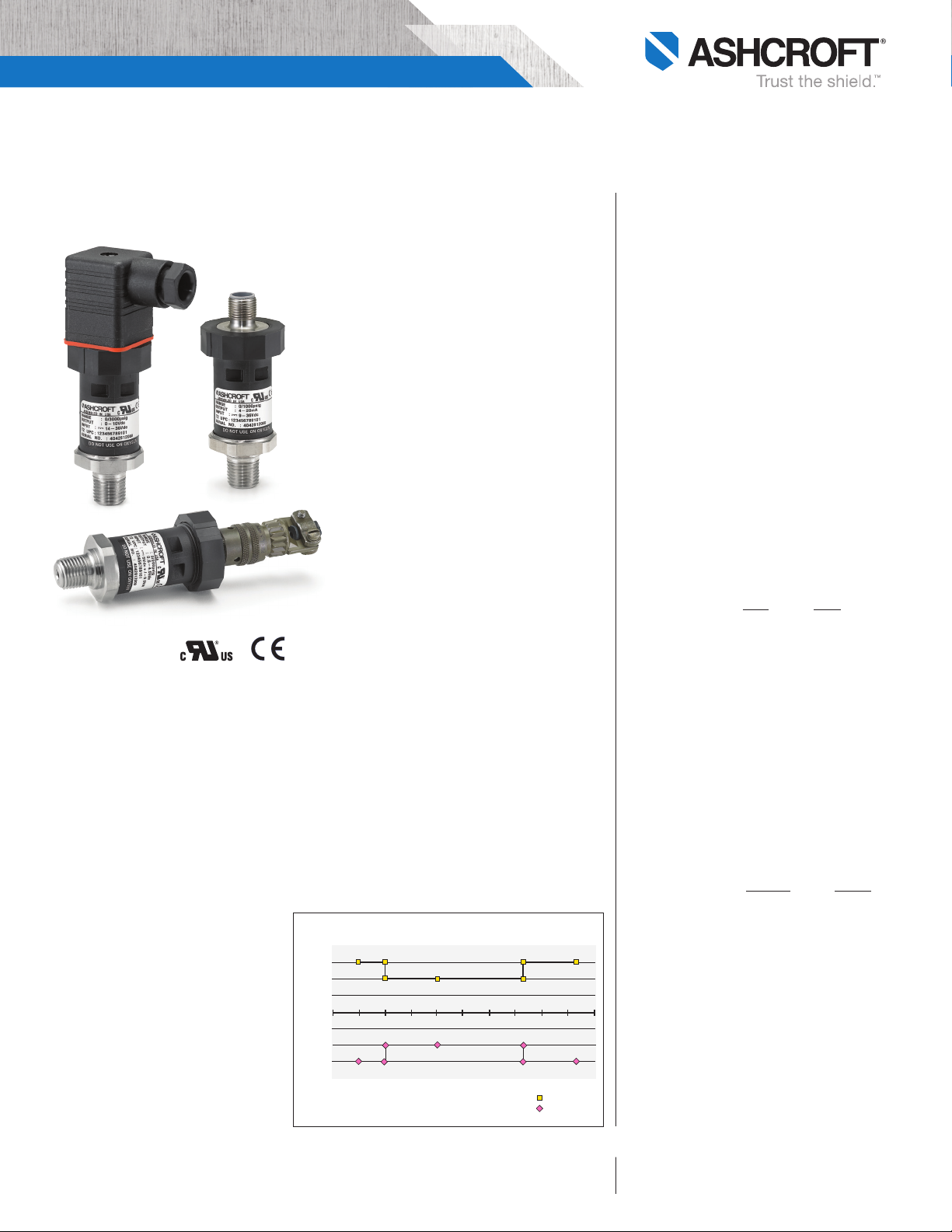
TOTAL ERROR BAND (TEB)
Error limits of all points (0-100% of range)
Error (% of span)
Ambient Temperature (C)
-60 -40 -20 0 20 40 60 80 100 120 140
2.0%
1.5%
1.0%
0.5%
0.0%
-0.5%
-1.0%
-1.5%
-2.0%
Pos Error Limit
Neg Error Limit
DIN 43650-A
Connection
LOOK FOR THESE AGENCY
MARKS ON OUR PRODUCTS
BULLETIN T2
M12
Connection
Bendix Style
Connection
APPLICATIONS
An affordable digitally compensated
instrument for general industrial
applications.
• Process Automation
• Compressor Control
• Hydraulic Systems
• Engine Monitoring
• Pump Control
• Pneumatics
• Refrigeration Equipment
• Presses
• Machine Tools
• Other General Industrial Applications
FEATURES
• 0.25% accuracy class
• Ranges 30 psi through 20,000 psi
• –40 to +125°C temperature capability
• All welded pressure construction
• Proven polysilicon thin film sensor
• Precision ASIC based electronics
• High EMI/RFI immunity rating
• Highly configurable
• Voltage and current outputs
• Choice of electrical connections
The T2 employs a polysilicon thin film sensor with
a proven long term stability. The sensor is electron
beam welded to a stainless steel pressure fitting
to ensure high overpressure ratings and integrity
in high shock, vibration and pressure cycling appli
cations. Through the use of a high performance
ASIC and modern digital compensation techniques
the T2 provides extraordinary performance over
temperature. The graph that follows depicts the
performance over temperature on a Total Error Band
basis – the Total Error Band includes not only tem
perature effects but also non-linearity, hysteresis
and non-repeatability.
All specifications are subject to change without notice.
All sales subject to standard terms and conditions.
© Ashcroft Inc. 2017 Rev. A 07/17
PERFORMANCE SPECIFICATIONS
Ref. Temperature, 21°C ±1°C (70°F, ±2°F)
Accuracy:
Static Accuracy Class: ±0.25% of span (BFSL Method)
including non-linearity, hysteresis, non- repeatability at
reference temperature
Temperature Effect:
–20°C to 85ºC <±1% of Span – Total Error Band
–40°C to –20ºC <±1.5% of Span – Total Error Band
–85°C to 125ºC <±1.5% of Span – Total Error Band
Total Error Band includes the combined effects of
non-linearity (Terminal Point Method), hysteresis,
non-repeatability, temperatureand zero offset and span
setting errors. For higher performance availability consult factory
Stability: Less than ±0.25% span/year
Durability: Tested to 50 million cycles
ENVIRONMENTAL SPECIFICATIONS
Temperature:
Compensated –40 to 125°C (–40 to 257°F)
Operating –40 to 125°C (–40 to 257°F)
Storage –40 to 125°C (–40 to 257°F)
Humidity: 0 to 100% R.H., no effect
FUNCTIONAL SPECIFICATIONS
Select from over 25 pressure ranges starting at 30 psi
and running through 20,000 psi. Compound (vacuum &
pressure) ranges are also available, see below.
Overpressure (F.S.): Proof Burst
750 psi & below 200% FS 1000% FS
1500 psi 200% FS 500% FS
3000 psi 200% FS 500% FS
5000 psi 150% FS 500% FS
7500 psi 120% FS 500% FS
10,000 psi 120% FS 240% FS
20,000 psi 120% FS 240% FS
Vibration: Random vibration (20 g) over temperature
range (–40° to 125°C). Exceeds typical MIL. STD.
requirements
Shock: 100gs, 6 ms
Drop Test: Withstands 1 meter on concrete 3 axis
Response Time: Less than 1 msec
Warm-up Time: Less than 500 msec typical
Position Effect: Less than ±0.01% span, typical
ELECTRICAL SPECIFICATIONS
Output Signals Available:
Supply
Voltage Output Excitation Current
0-5 Vdc, 3 wire 9-36 Vdc 5mA
0-10 Vdc, 3 wire 14-36 Vdc 5mA
1-5 Vdc, 3 wire 9-36 Vdc 4mA
1-6 Vdc, 3 wire 9-36 Vdc 4mA
Ratiometric Output
0.5-4.5 Vdc, 3 wire 5 Vdc ±0.5 Vdc 3.5mA
Current Output
4-20mA, 2 wire 9-36 Vdc
Reverse Polarity & Miswired Protected: Yes
Insulation Breakdown Voltage: 100 Vac
Insulation Resistance: Greater than 100 megohms at
100 Vdc
CE Compliance: Per EN 61326: 1997+ A1: 1998 + A2:
2001, Annex A (Heavy Industrial)
Ashcroft Inc., 250 East Main Street, Stratford, CT 06614 USA
Tel: 203-385-0648 • Fax: 203-385-0408
email: info@ashcroft.com • www.ashcroft.com
Page 2
Model T2 Pressure Transducer
UL Recognized component per IL-61010-1, CDA 22.2
6101-1 Electrical Equipment for Measurement, Control
and Laboratory use.
PHYSICAL SPECIFICATIONS
Wetted Materials: 304SS pressure connection and
17-4PH SS sensor diaphragm
Housing: 20% Glass Reinforced Nylon,
Fire retardant to UL94 V1
Available Process Connections (Male):
1
⁄8 NPT, 1⁄4 BSP, 1⁄4 NPT, G1⁄4 B, 7⁄16-20 UNF-2A
For other connections consult factory
Ingress Rating: Enclosure meets NEMA 4X, IP65
ELECTRICAL TERMINATION
• Pigtail: 3 feet of shielded cable, PVC jacket, 24 AWG
leads
• EN 175301-803, Form A (DIN 43650, Form A)
• Bendix style 4 pin, PTO 2A-8-4P or similar
• M12 x 1, 4 pin, Circular style
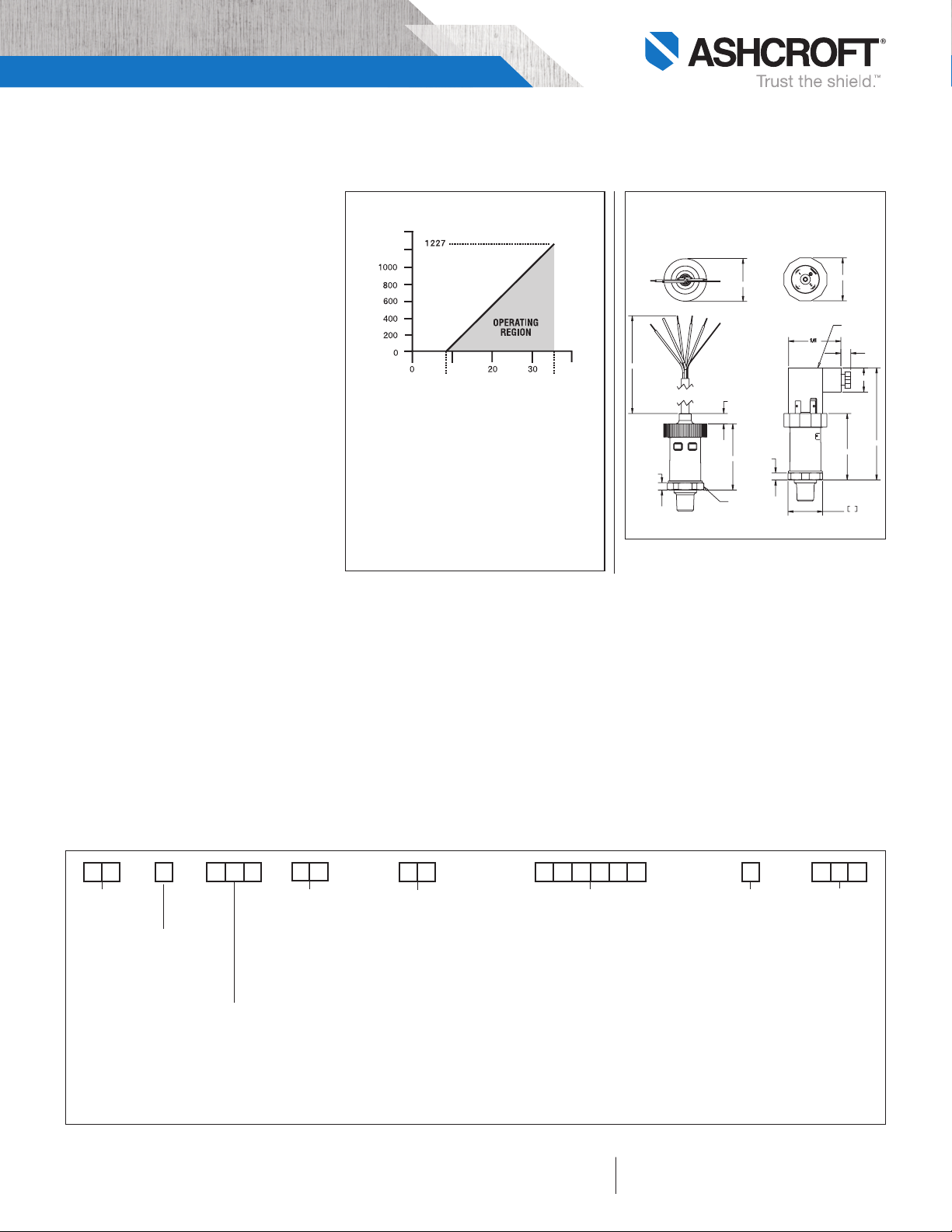
Power Supply Voltage vs. Loop Resistance
1400
1200
-Ohms)
L
Loop Resistance (R
(4-20mA ONLY)
10
9 (min)
Loop Supply Voltage (Vdc) [LSV]
36 (max)
To Determine minimum loop supply voltage:
LSV(min)=9(V)+[.022(A)*RL ]
Where:
LSV= Loop Supply Voltage (Vdc)
RL = RS+ RW (ohms)
RL = Loop Resistance (ohms)
RS = Sense Resistance (ohms) [Measuring Instrument]
RW = Wiring Resistance (ohms)
DIMENSIONS
SHIELDED CABLE
PVC Jacket, 3´ Length
Standard, 24 AWG Leads
ø
1.32
40
"L"
.23
MATING CONNECTOR
LOCATION AND SIZE
.32
2.03
27mm
1.06˝
HEX
M12 and Bendix style termination designs share similar
dimensions to those shown above.
.23
DIN FORM-A
Mates to Hirschmann
GDM 3009 or similar
ø
1.32
MATING CONNECTOR
LOCATION AND SIZE
2.04
27
1.063
.30
.75
3.450
How To Order
T 2
Type
Configuration
(T2)
Accuracy ±0.25% Static
Accuracy Class (BFSL)
1.0% Total Error Band
–20°C/+85°C
1.5% Total Error Band
–40°C/-20°C, 85/125°C
BULLETIN T2
Output Signal
05 = 0-5 Vdc
10 = 0-10 Vdc
15 = 1-5 Vdc
16 = 1-6 Vdc
42 = 4-20mA
RM = 0.5-4.5 Vdc
Ratio Metric
to 5Vdc
supply
Pressure Connection
M01 1⁄8 NPT-male
1
M02
⁄4 NPT-male
7
MEK
⁄16-20 SAE-male
MS2 1⁄4-19 bsp male†
1
MG2 G
⁄4 B male
Consult factory for other connections
† Not UL recognized above 10,000 psi range
††
Not CE Compliant
†
Electrical Termination
EN 175301-803, Form A (DIN 43650,
Form A) – Mates to Hirschmann
GDM 3009 or similar
DN = no mating conn.
D0 = w/mating conn., no cable
D2 = w/mating conn. 3´ shielded cable
M12 – Mates to Hirschmann
933 172-100 or similar
EW = no mating conn.
E0 = w/mating conn. no cable
E2 = w/mating conn. & 3´ shielded cable
Circular 4 Pin – Mates to Amphenol††
Bendix PTO6A-8-4S-SR or similar
B4 = no mating conn.††
H1 = w/mating conn., no cable††
L1 = w/mating conn. 3´ shielded cable
Pigtail – Shielded cable with PVC
Jacket and 24 AWG leads
F2 = w/3´ cable length
F3 = w/10´ cable length
Consult factory for additional cable lengths
††
psi Ranges
30# = 30 psi
50# = 50 psi
60# = 60 psi
100# = 100 psi
150# = 150 psi
200# = 200 psi
300# = 300 psi
400# = 400 psi
500# = 500 psi
750# = 750 psi
1000# = 1000 psi
1500# = 1500 psi
2000# = 2000 psi
3000# = 3000 psi
5000# = 5000 psi
6000# = 6000 psi
7500# = 7500 psi
10000# = 10000 psi
15000# = 15000 psi
20000# = 20000 psi
All specifications are subject to change without notice.
All sales subject to standard terms and conditions.
© Ashcroft Inc. 2017 Rev. A 07/17
Pressure Ranges
Compound Ranges
30#&vac = 30 psi/-14.7 psi
45#&vac = 45 psi/-14.7 psi
60#&vac = 60 psi/-14.7 psi
85#&vac = 85 psi/-14.7 psi
100#&vac = 100 psi/-14.7 psi
150#&vac = 150 psi/-14.7 psi
200#&vac = 200 psi/-14.7 psi
300#&vac = 300 psi/-14.7 psi
Ranges in bar, kPa and mPa are also available
Ashcroft Inc., 250 East Main Street, Stratford, CT 06614 USA
Tel: 203-385-0648 • Fax: 203-385-0408
email: info@ashcroft.com • www.ashcroft.com
G
Measurement
Type
G = Gauge Pressure,
Vented Housing
For sealed housing
(PSIS) consult factory
-
X 7
X-Variations
Consult Factory for
Available Options
Optional
 Loading...