

Page 1
Installation and Maintenance Instructions for
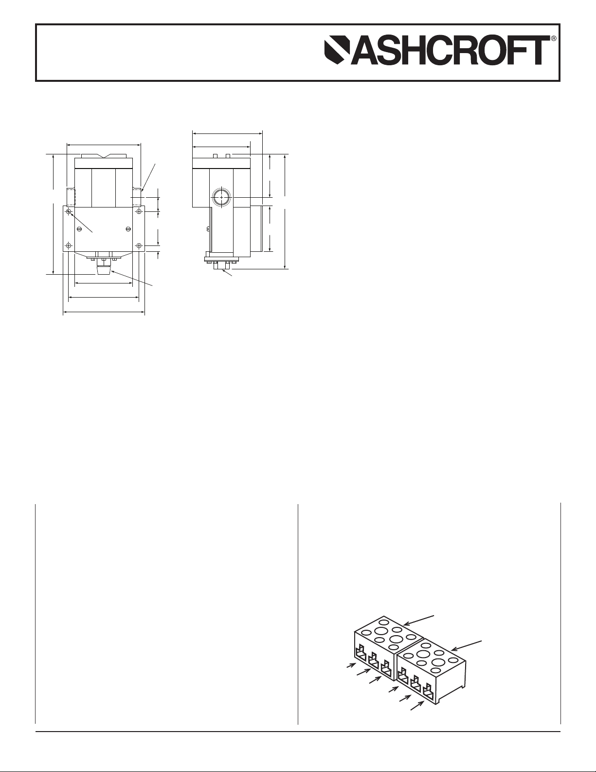
1.06
(
27)
2.30
(58)
0
.38
(
10)
4.75
(
121)
3.88
(99)
5
.50
(
140)
5.00
(
127)
Ø 0.31 X 4 HOLES
3/4 NPT
TYP
Ø
3.90
(99)
4
.70
(119)
2
.90
(74)
3.06
(
78)
7.72
1/4 NPT PORT
8
.08
1/2 NPT MALE &
1/4 NPT FEMALE
(205)
(8)
(
196
TERMINAL BLOCK
SWITCH A
TERMINAL BLOCK
SWITCH B
2
1
3
2
1
3
NC
NO
C
NC
NO
C
ASHCROFT®High Pressure P-Series
Snap Action Switches with Buna N, Viton and
Teflon Diaphragms for Pressure Control
psi Ranges
N4 – 5.0 lb. (2.3 )
N7 – 5.6 lb. (2.5 )
STANDARD RANGES
1000, 2000, 3000 psi
INTRODUCTION
The Ashcroft pressure control is a precision device which fea-
ing control to pressure line, always use the wrench flats or hex
on the pressure connection. Never tighten by twisting the case.
tures a snap action switch. Fixed deadband is available with
single or dual SPDT independently adjustable switches with
various electrical ratings. Adjustable deadband is available with
a SPDT switch with various electrical ratings. Several wetted
material constructions for compatibility with pressure media may
be obtained.
The “P” Series Ashcroft snap action pressure switch is available
in both standard NEMA~ and explosion-proof NEMA 7 & 9 configurations. The enclosure is an epoxy coated aluminum casting.
INSTALLATION
This control is a precision instrument and should never be left
with internal components exposed. During installation insure that
covers are in place and conduit openings are sealed.
MOUNTING
Four holes in the bracket supplied are used in surface mounting
of the control. Location of these holes is shown on the general
dimension drawings. An optional pipe mounting bracket is also
available. Mount on a vibration free surface or pipe. When tighten-
© 2014 Ashcroft Inc., 250 East Main Street, Stratford, CT 06614-5145, USA, Tel: 203-378-8281, Fax: 203-385-0499, www.ashcroft.com
All sales subject to standard terms and conditions of sale. I&M009-10212 P Series 03/2014
ELECTRICAL CONNECTION
Remove top cover, cover unscrews (CCW).
On all units except one with terminal blocks-wire directly to the
switch according to circuit requirements. Units with terminal
blocks-wire directly to terminal blocks as required. Terminals are
marked common, norm open and norm closed.
Page 2
Installation and Maintenance Instructions for
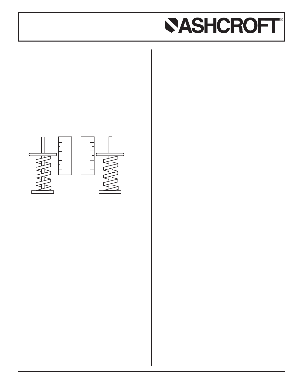
A
B
0
20
40
60
0
20
40
60
ASHCROFT®High Pressure P-Series
Snap Action Switches with Buna N, Viton and
Teflon Diaphragms for Pressure Control
CONDUIT CONNECTIONS
3
wo
T
with a cap. It is recommended that Teflon tape or other sealant
be used on conduit bushing or plug threads to ensure integrity
of the enclosure. NEMA 7 & 9 enclosures require proper conduit
seals and breathers as per the National Electrical Code.
SETPOINT ADJUSTMENTS
Series PP-S Single Switch – Remove front cover, held in place
by two screws. For setpoint adjustment to within + 1% of nominal range, use a suitable reference such as an Ashcroft
Duragauge or test gauge. Monitor switch with a suitable pilot
light or meter. Pressurize the system to the required setpoint
and turn the adjusting wheel until the switch changes mode.
When the setpoint has been achieved, raise and lower the pressure to insure that the setpoint is correct.
PT holes are provided, one fitted with a plug, the other
⁄
4 N
Series PP-D Dual Switch – Remove front cover, held in place
by two screws. There are two range adjusting wheels. The
adjusting wheel on the left (labeled A) controls the left switch,
the adjusting wheel on the right (labeled B) controls the right
switch. The switches are set independently.
NOTE: The units are calibrated at the factory such that for proper
operation switch B setpoint must be set higher than
switch A setpoint.
For setpoint adjustment to within ±1% of nominal range mount
the switch on a calibration stand, and use a suitable reference
such as an Ashcroft Duragauge or test gauge. Monitor switch
with a suitable pilot light or meter.
Pressurize the system to the required setpoint and turn the
adjusting wheel until the switch changes mode. When the setpoint has been achieved, raise and lower the pressure to insure
that the setpoint is correct. This must be done for both setpoint
A and setpoint B.
Series PP-A Adjustable Deadband SwItch – Remove front
cover, held in place by two screws. The adjusting wheel labeled
A controls the resetpoint of the switch. The adjusting wheel
labeled B controls the setpoint of the switch.
Note: The units are calibrated at the factory such that for proper
operation setpoint B is always higher than resetpoint A.
For accurate setpoint adjustment, mount the switch on a calibration stand, and use a suitable reference such as an Ashcroft
Duragauge or Test Gauge. Monitor switch with a suitable pilot
light or meter. Pressurize the system to the required setpoint.
Move adjusting wheel on spring B until switch changes mode.
Then lower pressure to the resetpoint, move adjusting wheel on
spring A until the switch changes mode. Raise and lower pressure to insure that setpoint is correct. Repeat as necessary.
CAUTIONS TO OBSERVE
Switch Applications On Continuous Static Pressure:
Pressure switches that contain BUNA, VITON or TEFLON
diaphragms can experience some amount of compression set of
the diaphragm in high static pressure applications. This compression set has the potential to shift the switch setpoint while in service. The setpoint can shift by approximately 2% (typically less
than 1%) from the original setting. To assure optimal long term
setting accuracy, Ashcroft recommends the switch setting be
checked after 30 Days in service and reset if necessary. As with
any calibrated instrument, Ashcroft recommends regular inspection of operation and setpoint setting.
© 2014 Ashcroft Inc., 250 East Main Street, Stratford, CT 06614-5145, USA, Tel: 203-378-8281, Fax: 203-385-0499, www.ashcroft.com
All sales subject to standard terms and conditions of sale. I&M009-10212 P Series 03/2014
 Loading...