

Page 1
Data Sheet
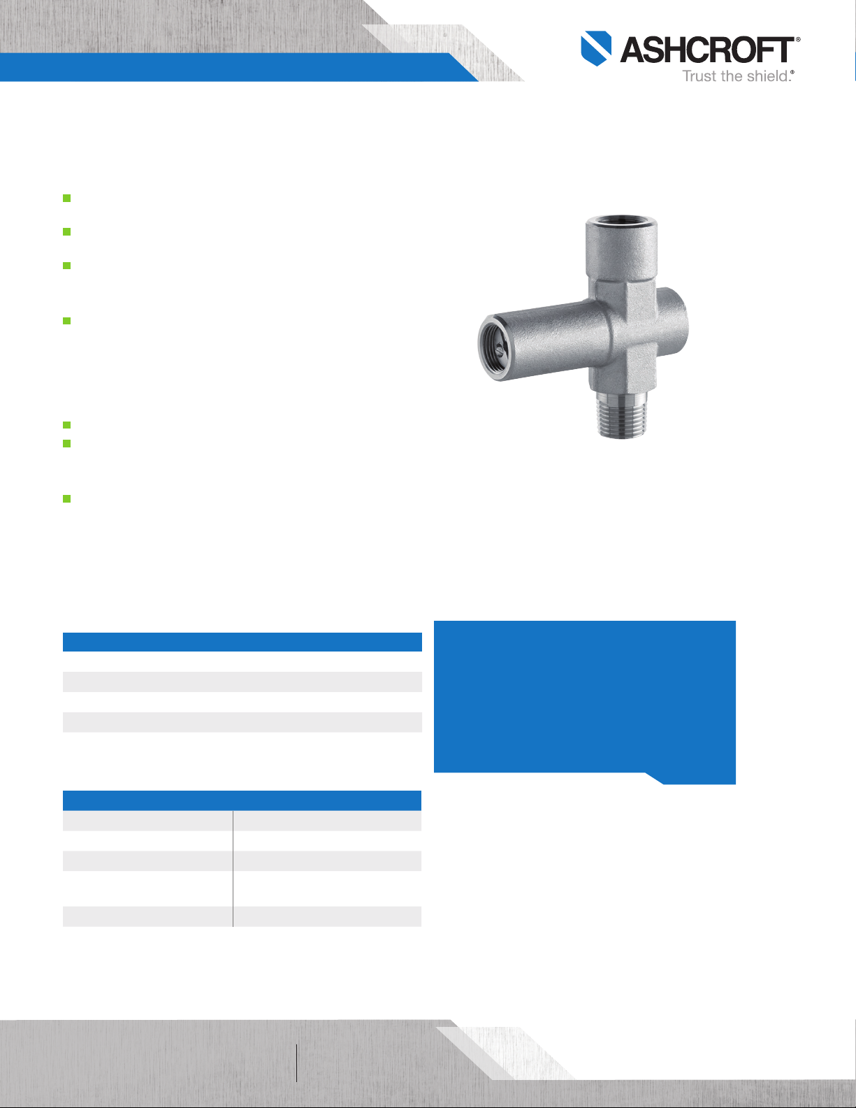
PL02 - Pressure Limiting Valve
FEATURES
Protects instrument assembly from over pressure
and severe pressure spikes
Prevents damage, loss of accuracy and or rupture
of sensing elements
316Ti SS construction
TYPICAL USES
Oil & Gas Industry
• Upstream: Onshore/offshore production
• Midstream: Transport, storage and natural
gas compression
• Downstream: Refineries and petrochemical
industries
Chemical Industry
Power Plants
• Conventional power plants
• Flue gas desulfurization plants
Other Industries
• Waste incineration plants
• Seawater desalination plants
• Steel mills
• Cement plants
PL02
Pressure Limiting Valve
SPECIFICATIONS
Process Connection: ¼ NPT Male, ½ NPT Male
Instrument Connection: ¼ NPT Female, ½ NPT Female
Construction: 316Ti SS
Maximum Pressure Rating: 14,500 psi
Maximum Temperature Rating
Minimum Temperature Rating
FKM (FPM by ISO):
WETTED COMPONENTS
Parts Material
Body & Valve Stem, Screw plug 316L SS
Needle Tip 316Ti SS
Piston seal
Gland nut 304 SS
175°F (80°C)
14°F (-10°C)
FKM (equivalent to FPM by ISO)
175°F (80°C) to 14°F (-10°C)
KEY BENEFITS
• Isolates instrument assembly from process
when set pressure is realized
• Automatically resets after 25% drop in pressure
from setpoint
• Available setpoints from 6 psi to 8,700 psi
• Built in pressure snubbing design
All speci fications are subject to change without notice.
All sales subject to standard terms and conditions.
©2018 Ashcroft Inc. PL02_accessory_ds1.0, Rev. G, 03/19
ashcroft.com
info@ashcroft.com
1.800.328.8258
of 21
Page 2
Data Sheet
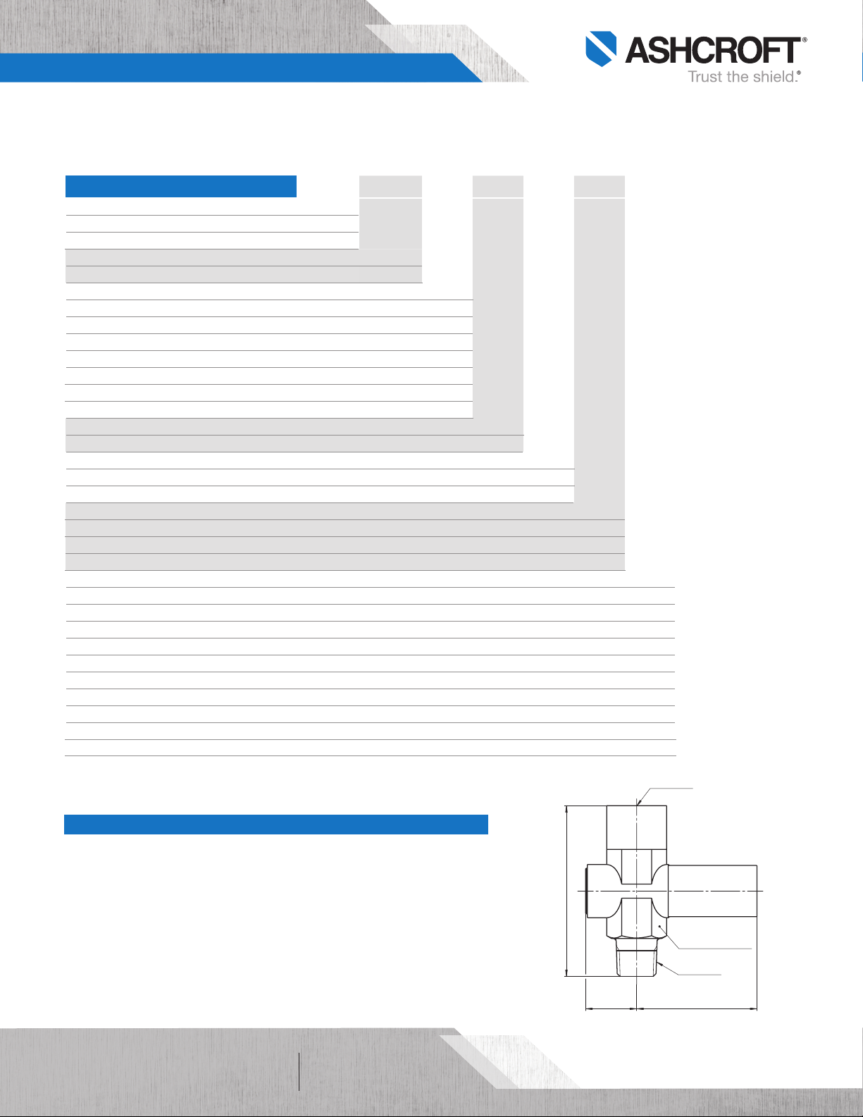
L
[
1.04
]
26.5
[
2.46
]
62.5
½ -¼ NPT Male
[
1.06
]
ACROSS FLATS 27
½ -¼ NPT Male
[
3.54
]
90
PL02 - Pressure Limiting Valve
ORDERING CODE Example:
04 PL02 A ST 50 0010# –XC3
Process Connection
04 - ½ NPT Male 04
02 - ¼ NPT Male
Series Code
PL02 - Valve PL02
Style (setpoint) psi bar/kg/cm
2
A - Style A 6-36 0.4-2.5 A
B - Style B 30-85 2-6
C - Style C 75-360 5-25
D - Style D 300-850 20-60
E - Style E 750-3,600 50-250
F - Style F 3,500-5,800 240-400
G - Style G (available in ¼˝ only) 5,800-8,700 400-600
Material
ST - 316Ti SS ST
Instrument Connection
50 -
½ NPT Female 50
25 - ¼ NPT Female
Factory Set Range (4-digit) *other ranges available on request
0010# - 10 psi* 0010#
0002BR - 2 bar
0010KG - 10 kilogram
Options (If choosing option(s) must include an “X”) –X __
HY - Hydrostatic testing
NH - SS Tags
C3 - Material traceability report C3
E9 – Assembly: Instrument, Pressure limiting valve, siphon
F7 – Assembly: Instrument, Pressure limiting valve, Diaphragm seal or isolation ring
F9 – Assembly: Instrument, Capillary, Pressure limiting valve, Snubber, Diaphragm seal or isolation ring
K2 – Assembly: Instrument, Capillary, Pressure limiting valve, Diaphragm seal or isolation ring
L2 – Assembly: Instrument, Pressure limiting valve, Diaphragm seal or isolation ring
5G – Assembly: Instrument, Pressure limiting valve
(1)(2)
(1)
(1)
(1)
(1)
(1)
6B - Cleaned for oxygen service
(1) – Assemblies are configured in order as listed. Consult factory for details on configuration and for other assembly options.
All components in assembly must be purchased as separate items.
(2) – Coil and pig tail siphons will only be hand tightened onto the assembly for filling purposes.
DIMENSIONS
For reference only, consult Ashcroft for specific dimensional drawings
All speci fications are subject to change without notice.
All sales subject to standard terms and conditions.
©2018 Ashcroft Inc. PL02_accessory_ds1.0, Rev. G, 03/19
ashcroft.com
of 22
info@ashcroft.com
1.800.328.8258
 Loading...