

Page 1
Installation and Maintenance Instructions for
ASHCROFT®P-Series Snap Action
Switches for Differential Pressure Control
INTRODUCTION
The Ashcroft pressure control is a precision device which
features a snap action switch. Fixed deadband is available with
single or dual SPDT Independently adjustable switches with
various electrical ratings. Adjustable deadband is available with
a SPDT switch with various electrical ratings. Several wetted
material constructions for compatibility with pressure media may
be obtained.
The “P” Series Ashcroft snap action pressure switch is available
in both standard NEMA-4 and explosion-proof NEMA 7 & 9 configurations. The enclosure is an epoxy coated aluminum casting.
INSTALLATION
This control is a precision Instrument and should never be left
with internal components exposed. During installation ensure
that covers are in place and conduit openings are sealed.
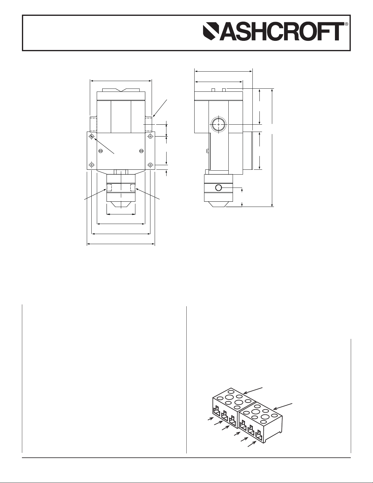
MOUNTING
Four holes in the bracket supplied are used in surface mounting
of the control. Location of these holes is shown on the general
dimension drawings. An optional pipe mounting bracket is also
available. Mount on a vibration tree surface or pipe. When tightening control to pressure line, always use the wrench flats or
hex on the pressure connection. Never tighten by twisting the case.
PRESSURE CONNECTIONS
For operation as a differential pressure control-connect the high
pressure to the side port marked “H” and the low pressure to the
side port marked “L.”
ELECTRICAL CONNECTION
Remove top cover, cover unscrews (CCW).
On all units except one with terminal blocks – wire directly to
the switch according to circuit requirements. Units with terminal
blocks – wire directly to terminal blocks as required. Terminals
are marked common, norm open and norm closed.
1.06
(27)
2.30
(58)
0.38
(10)
5.00
(127)
Ø 0.31 X 4 HOLES
(8)
3/4 NPT
TYP
Ø 3.90
(99)
4.70
(119)
2.90
(74)
3.06
(78)
(243)
(59)
FEMALE
PORT
H
L
(39)
Ø 2.31
3.9
(99)
4.75
(121)
5.50
(140)
1/4 NPT
HIGH
PRESSURE
FEMALE
PORT
1/4 NPT
LOW
PRESSURE
1.55
9.55
STANDARD RANGES
15, 30, 60, 100, 200, 400 psid
© 2007 Ashcroft Inc., 250 East Main Street, Stratford, CT 06614-5145, USA, Tel: 203-378-8281, Fax: 203-385-0499, www.ashcroft.com
All sales subject to standard terms and conditions of sale. I&M009-10011-10/00 (250-2550) AMR 12/07
3
2
C
NO
NC
NC
NO
TERMINAL BLOCK
SWITCH A
1
1
2
3
C
TERMINAL BLOCK
SWITCH B
Page 2
CONDUIT CONNECTIONS
Tw o
3
⁄
4 NPT holes are provided, one fitted with a plug, the other
with a cap. It is recommended that Teflon tape or other sealant
be used on conduit bushing or plug threads to ensure integrity
of the enclosure. NEMA 7 & 9 enclosures require proper conduit
seals and breathers as per the National Electrical Code.
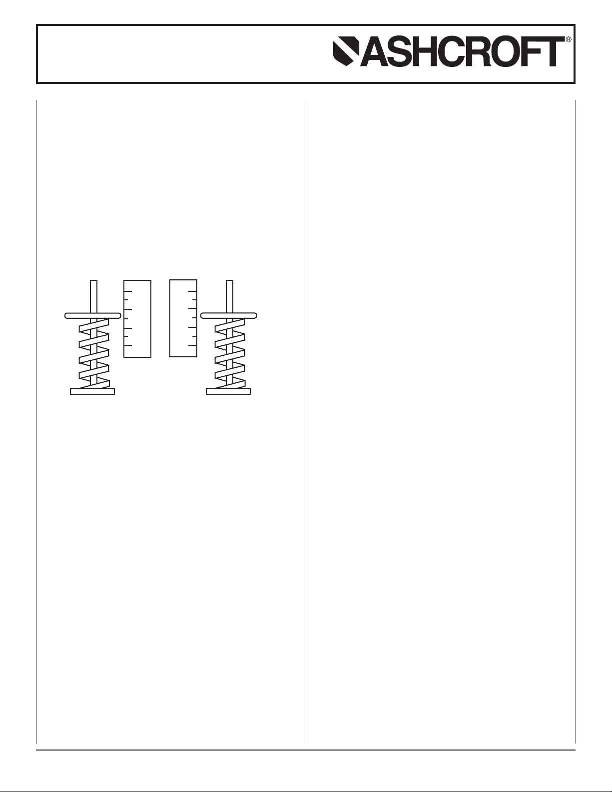
SETPOINT ADJUSTMENTS
Series PD-S Single Switch – Remove front cover, held in place
by two screws. For setpoint adjustment to within ±1% of nominal
range, use a suitable reference such as an Ashcroft Duragauge
or test gauge. Monitor switch with a suitable pilot light or meter.
Apply LOW pressure. Then apply HIGH pressure to the required
setpoint and turn the adjusting wheel until the switch changes
mode. When the setpoint has been achieved, raise and lower
HIGH pressure to insure that differential pressure between
HIGH and LOW pressures is correct.
Series PD-D Dual Switch – Remove front cover, held in place
by two screws. There are two range adjusting wheels. The
adjusting wheel on the left (labeled A) controls the left switch,
the adjusting wheel on the right (labeled B) controls the right
switch. The switches are set independently.
Note: The units are calibrated at the factory such that for proper
operation switch B setpoint must be set higher than
switch A setpoint.
For setpoint adjustment to within ±1% of nominal range mount
the switch on a calibration stand, and use a suitable reference
such as an Ashcroft Duragauge or test gauge. Monitor switch
with a suitable pilot light or meter.
Apply LOW pressure. Then apply HIGH pressure to the
required setpoint and turn adjusting wheel until the switch
changes mode. When the setpoint has been achieved raise and
lower the pressure to insure the setpoint is correct. This must be
done for both setpoint A and setpoint B.
Series PD-A Adjustable Deadband Switch – Remove front
cover, held in place by two screws. The adjusting wheel labeled
A controls the re-setpoint of the switch. The adjusting wheel
labeled B controls the setpoint of the switch.
Note: The units are calibrated at the factory such that for proper
operation setpoint B is always higher than re-setpoint A.
For accurate setpoint adjustment, mount the switch on a calibration stand, and use a suitable reference such as an Ashcroft
Duragauge or Test Gauge. Monitor switch with a suitable pilot
light or meter. Apply low pressure. Then apply high pressure to
the required setpoint. Move adjusting wheel for switch B until
switch changes mode. Then lower the HIGH pressure to the resetpoint and move adjusting whee: for switch A until the switch
changes mode. Raise and lower HIGH pressure to insure that
differential pressure between HIGH and LOW pressure is
correct. Repeat as necessary.
Installation and Maintenance Instructions for
ASHCROFT®P-Series Snap Action
Switches for Differential Pressure Control
© 2007 Ashcroft Inc., 250 East Main Street, Stratford, CT 06614-5145, USA, Tel: 203-378-8281, Fax: 203-385-0499, www.ashcroft.com
All sales subject to standard terms and conditions of sale. I&M009-10011-10/00 (250-2550) AMR 12/07
0
20
40
60
A
0
20
40
60
B
 Loading...