

Page 1
Installation and Maintenance Instructions
3.31
3.26
5.62
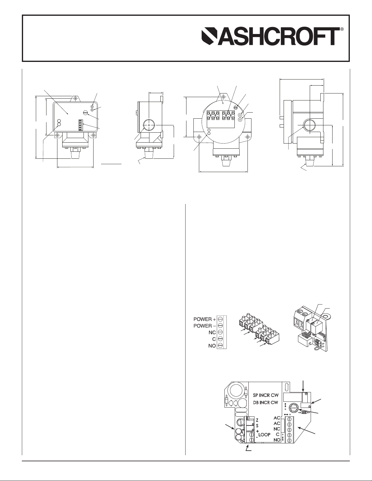
INDICATING LEDS
NOTE:THIS VIEW SHOWN
WITH COVER REMOVED
TERMINAL
BLOCK
GROUND
SCREW
DEADBAND
ADJUSTMENT
KNOB
SETPOINT ADJUSTMENT KNOB
SP INCR CW
DB INCR CW
AC
AC
NC
C
NO
1.26
3.0
3/4 NPT
1/4 NPT MALE
PRESSURE CONNECTION
(143)
(84)
(83)
(32)
(7
SP INCR CW
DB INCR CW
3.62
4.37
INDICATING
LEDS
TERMINAL BLOCKS
GROUND SCREW
SETPOINT
ADJUSTMENT
KNOB
DEADBAND
ADJUSTMENT
KNOB
AC AC NC C NO
6.55
3.67
3.96
1.25
3/4 NPT
FEMALE
NOTE:THIS VIEW SHOWN
WITH COVER REMOVED
1/4 NPT MALE
PRESSURE CONNECTION
(92)
(111)
(101)
(32)
(166)
(93)
NC
NO
C
POWER +
POWER -
+
SPAN
ZERO
Setpoint Potentiometer
Deadband
Potentiometer
Ground Screw
N4 Ter minal Block
INDICATING LED’S
GREEN Normally Open
RED Normally CLOSED
4-20mA Output Option
for N Series Electronic Pressure Switch
INTRODUCTION
The Ashcroft
which features an Ashcroft
sure sensor (Transducer). Pressure switches are available for
operation on pressure with fixed or variable deadband (differential).The standard electrical switch is a SPDT sealed mechanical relay. The wetted materials are 17-4PH and 316 stainless
steel.The Ashcroft
NEMA 4 and explosion proof NEMA 7/9 enclosure styles. Both
enclosures are epoxy coated aluminum castings.
INSTALLATION
These controls are precision instruments and should never be
left with internal components exposed. After installation, ensure
that the covers are in place and the conduit openings are
closed.
MOUNTING N4 & N7 SERIES
There are three holes external to the enclosure for surface
mounting. The locations of these holes are shown on the general dimension drawing. The controls may also be mounted directly on the pressure line using the pressure connection. When
tightening the control to the pressure line, always use the
wrench flats or the hex on the lower housing.
ELECTRICAL CONNECTIONS
WARNING: Cover with display has a ribbon cable connected to the
cover that can come loose. Take care when opening.
Remove cover.
N4 Series – Two screws hold cover to enclosure
N7 Series – Cover unscrews
CONDUIT CONNECTIONS
Note: It is recommended that Teflon tape or other sealant be
N4 Series Standard – One
N7 Series Standard – Two
N4 and N7 Series – XJL Variation –
N4 Series – XJL Variation –
© 2007 Ashcroft Inc., 250 East Main Street, Stratford, CT 06614-5145, USA, Tel: 203-378-8281, Fax: 203-385-0499, www.ashcroft.com
All sales subject to standard terms and conditions of sale
N4
1.8 lb
(.81 kg)
®
pressure switch is a precision built control device
®
used on the conduit, bushing or plug threads to ensure
the integrity of the enclosure.
manent plug. NEMA 7/9 enclosure require proper conduit
seals and breathers as per the National Electrical Code.
3
⁄4 to1⁄2 NPT reducing bushings.
Two 3⁄4 NPT conduit holes.This option is recommended when
ordering 4-20mA output.
®
K-Series polysilicon thin film pres-
pressure switch is furnished in the standard
3
⁄4 NPT conduit holes with
. I&M009-10026-6/04 (250-B145-01) Rev. 3 AMR 05/10
3
⁄4 NPT conduit hole right side.
3
⁄4 NPT conduit holes with one per-
N7
Ranges –
60, 100, 200, 300, 500, 750, 1000, 2000, 3000, 5000, 7500,
10,000, 15,000, 20,000 psi
N4 & N7 SERIES
SPDT – Wire directly to the terminal block according to circuit
requirements. For 120Vac 60 Hz switch, wire power lines to
terminal marked ac. For 24 Vdc switch, wire positive power line
to terminal marked 24Vdc + and wire negative power line to
terminal marked 24Vdc –.
N4 & N7 SERIES
Adjustment of Setpoint
A 25 turn adjustment potentiometer is located at the upper right
corner on the inside of the enclosure.
For accurate setpoint calibration, mount the switch on a calibration stand, a pump or catalog no. 1305 deadweight gauge
tester. A suitable reference standard such as an Ashcroft
Duragauge or test gauge is necessary to observe changes in
pressure.
N4
TERMINAL BLOCKN7TERMINAL BLOCK
4-20mA
OUTPUT OPTION
Page 2

Installation and Maintenance Instructions
0
10
12 20 30 36
40
1250
1091
1000
750
500
250
0
545
24
OPERATING
REGION
for N Series Electronic Pressure Switch
As received, the pressure switch will normally be set to
approximately 90% of the indicated range. Pressurize the system to the required setpoint and turn the adjustment potentiometer until the switch changes mode. Clockwise rotation of
the potentiometer will increase the setpoint and counter-clockwise rotation of the potentiometer will decrease the setpoint.
When the setpoint has been achieved, raise and lower the
pressure to ensure that the setpoint is correct.
The indicating LEDs will show red when the pressure is below
the setpoint and green when the pressure is above the setpoint.
For N4 XEA Switches Only – The setpoint is adjusted by a
ten turn potentiometer located externally on the top right of the
case.The setpoint is adjusted as above.
Adjustment of Deadband – A four turn adjustment potentiometer is located at the upper right corner on the inside of the
enclosure just below the setpoint potentiometer.
The deadband is adjusted as above. Clockwise rotation of the
potentiometer will increase the deadband and counter-clockwise rotation of the potentiometer will decrease the deadband.
After installation of the control replace cover to protect internal parts from the environment.
POWER SUPPLY – N4 & N7 SERIES 4-20mA OPTION
The maximum supply voltage for a 4-20mA current output
transducer is 36 dc while the minimum supply voltage is
dependent upon the loop resistance of the circuit. The load
limitation chart shows the minimum supply voltage (V
required for a given loop resistance (R
LOOP
).
NOISE
For minimum noise susceptibility, avoid running the transducer’s
cable in a conduit that contains high current AC power cables.
Where possible avoid running the cable near inductive equipment.
ADJUSTMENT POTENTIOMETERS
The zero and span pots are accessible through the front when
the cover is off. Remove the cover carefully. The zero and span
pots are labeled. For additional conduit hole on N4 Series,
order option (XJL).
min
)
WARNING!
This instrument is susceptible to damage when exposed
to static electrical charges. To avoid damage observe the
following:
• Ground the body of the instrument BEFORE
electrical connections
• When disconnecting, remove the ground LAST
CAUTION: Pressure spikes in excess of the rated overpressure capability of the instrument may cause irreversible electrical and/or mechanical damage to the pressure measuring
and containing element(s).
Load Limitations 4-20mA Output
Loop Resistance (ΩΩ)
LOOP SUPPLY VOLTAGE (VDC)
Vmin = 12V+ [.022A*(R L)]
*includes a 10% safety factor
RL = RS + RW
RL = Loop Resistance (ohms)
RS = Sense Resistance (ohms)
RW = Wire Resistance (ohms)
making any
.
© 2007 Ashcroft Inc., 250 East Main Street, Stratford, CT 06614-5145, USA, Tel: 203-378-8281, Fax: 203-385-0499, www.ashcroft.com
All sales subject to standard terms and conditions of sale
. I&M009-10026-6/04 (250-B145-01) Rev. 3 AMR 05/10
 Loading...