

Ashcroft N Service Manual
N-Series Electronic Pressure Switches
IDEAL FOR PRESSURE ALARM,
SHUTDOWN, CONTROL ON –
• Machine tools
• Injection molding machines
• Presses
• Pumps
• Hydraulic systems
• Turbines and compressors
• Pipelines
• Most process applications
• All high-cycle applications
Ashcroft®N-Series electronic pressure
switches have proven reliable in the toughest industrial applications. The pressure
sensor is a standard Ashcroft K-Series
thin film transducer. The signal developed
in the transducer is processed on a conformal coated printed circuit board to produce an output to a high quality electromechanical relay, which is rated for
10,000,000 cycles at rated load! The result
is a long lasting pressure switch that will
outlast mechanical switches in high cycle
applications such as metal stamping
presses, plastic injection molding
machines, and other machine tool and
special equipment. N-Series also features
narrow, adjust-able deadbands that can be
adjusted to less that 0.5% of range, solving many pipeline and elevated tank applications that are out of the reach of
mechanical products.
The indicating model is ideally suited for
applications where both a pressure indicator and a switch output for alarm, shutdown, control or interlock are needed.
Sludge and slurry applications in wastewater and pulp and paper mills often
require costly diaphragm seals to isolate
instruments from the clogging effects of the
process. You can save money by installing
N-Series with indication on a single seal.
You can even set the switch set and reset
points on a test bench without pressure on
the system, using the indicator and status
lights. Look for these additional features.
PERFORMANCE SPECIFICATIONS
Ashcroft Model: N-Series
Accuracy Class (F.S.): 1.0%
Nonlinearity
Terminal Point* ±0.7%
B.F.S.L. ±0.4%
Hysteresis ±0.2%
Nonrepeatability ±0.07%
Interchangeability ±1.0%
*Includes hysteresis
Stability: ±0.5% F.S./year non-cumulative
Durability: 108cycles 20/80% F.S. with negligible
performance change
Response time: Less than 5m sec
ENVIRONMENTAL CHARACTERISTICS
Temperature Limits:
Storage –65/+250°F
Operating –20/+180°F
Compensated –20/+160°F
Thermal Coefficients (70°F ref.):
Accuracy Zero and Span
1.0% ±0.040% F.S./°F
ELECTRICAL SPECIFICATIONS
Output Signal: Supply Voltage:
4-20mA (2 wire) 36 Vdc unregulated
Reverse polarity protected.
Zero Offset: ±1.0%F.S.
MECHANICAL SPECIFICATIONS
Standard Construction Materials:
Wetted Parts:
Diaphragm — 17-4PH SS
Pressure Connection —316SS
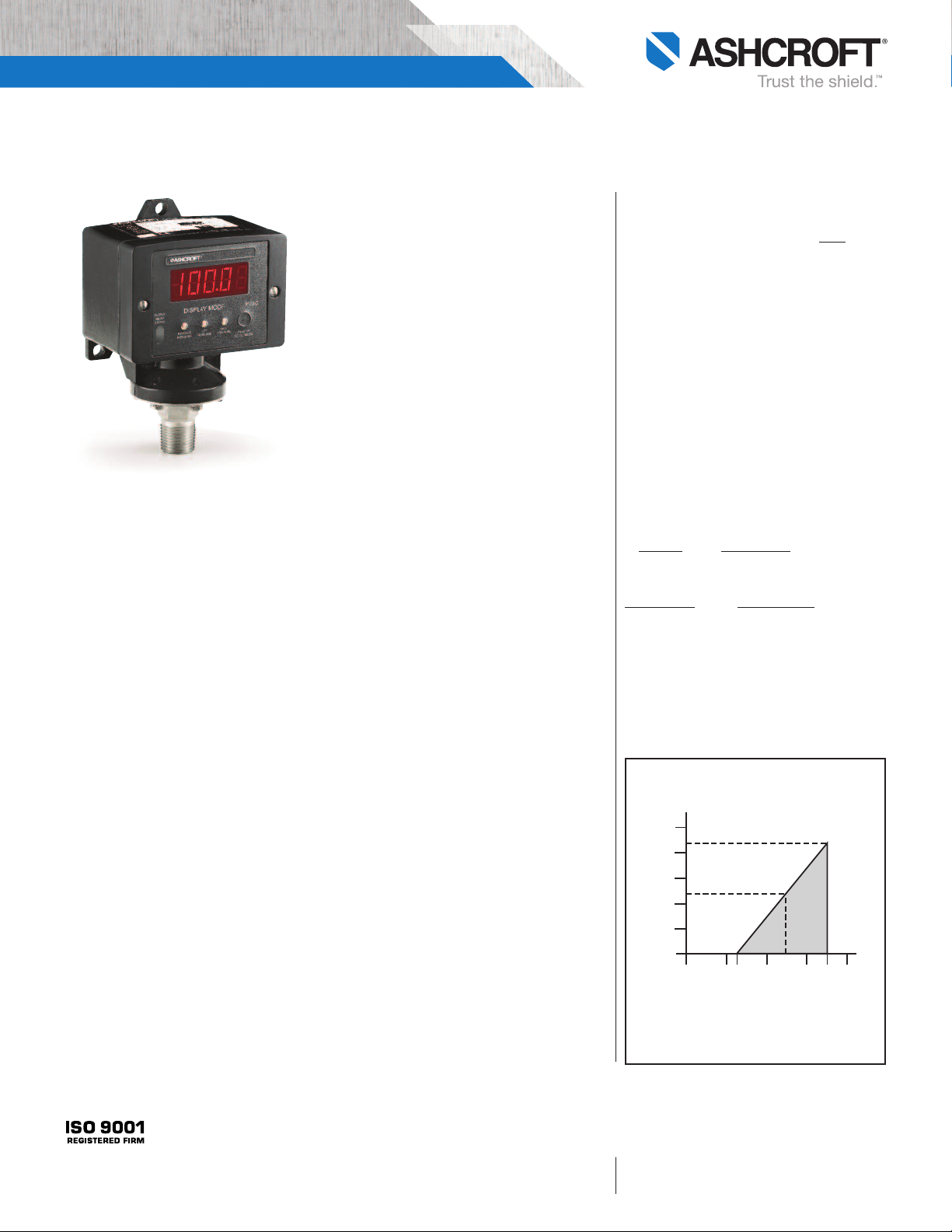
Load Limitations 4-20mA Output
Loop Resistance (Ω)
1250
1091
1000
750
545
500
250
0
0
Vmin = 12V+ [.022A*(R L)]
*includes a 10% safety factor
RL = RS + RW
RL = Loop Resistance (ohms)
RS = Sense Resistance (ohms)
RW = Wire Resistance (ohms)
10
12 20 30 36
OPERATING
REGION
24
40
BULLETIN SW15
All specification s are subject to change without not ice.
All sales subject to standard term s and conditions.
© Ashcroft Inc. 2008 07/14
Ashcroft Inc., 250 East Main Street, Stratford, CT 06614 USA
Tel: 203-378-8281 • Fax: 203-385-0408
email: info@ashcrof t.com • www.ashcroft .com
N-Series Electronic Pressure Switches
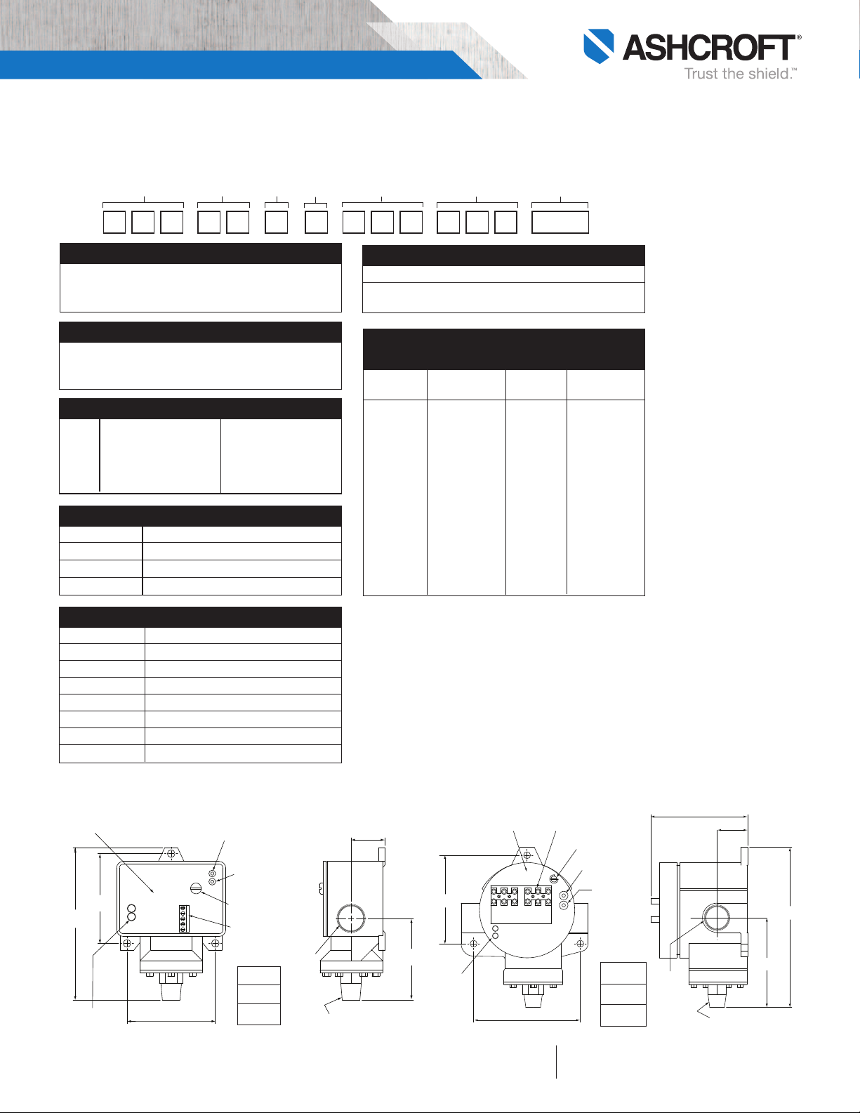
SP INCR CW
DB INCR CW
3.62
4.37
INDICATING
LEDS
TERMINAL BLOCKS
GROUND SCREW
SETPOINT
ADJUSTMENT
KNOB
DEADBAND
ADJUSTMENT
KNOB
AC AC NC C NO
6.55
3.67
3.96
1.25
3/4 NPT
FEMALE
NOTE: THIS VIEW SHOWN
WITH COVER REMOVED
1/4 NPT MALE
PRESSURE CONNECTION
(92)
(111)
(101)
(32)
(166)
(93)
3.31
3.26
5.62
INDICATING LEDS
NOTE: THIS VIEW SHOWN
WITH COVER REMOVED
TERMINAL
BLOCK
GROUND
SCREW
DEADBAND
ADJUSTMENT
KNOB
SETPOINT ADJUSTMENT KNOB
SP INCR CW
DB INCR CW
AC
AC
NC
C
NO
1.26
3.01
3/4 NPT
1/4 NPT MALE
PRESSURE CONNECTION
(143)
(84)
(83)
(32)
(76)
N-SERIES PRESSURE SWITCH MODEL NUMBER:
T
o specify the exact switch desired select entries from appropriate tables as shown in example below.
12 45
367
N P A N 4 L S 0 1 X E A 30 PSI
D
1 – FUNCTION
NPA – Single setpoint, adjustable deadband
NPI – Single setpoint, adjustable deadband, process
and setpoint indication
2 – ENCLOSURE
N4 – Watertight NEMA 3, 4, 4X, 13 and IP66
N7 – Explosion proof NEMA 3, 4, 4X, 13, 7, 9 and
IP66 – Not available with Model NPI (display)
3 – OUTPUT
D SPDT Relay 10A, 250 Vac
10A, 30 Vdc
I SPDT Relay and 10A, 250 Vac
Current Output 10A, 30 Vdc
and 4-20mA
4 – POWER REQUIREMENT
Code
L 110 Vac, 50/60Hz
C 24 Vdc
V 250 Vac, 50/60Hz
5 – PRESSURE PORT
Code Description
S01 1⁄8 NPT Male
S02 1⁄4 NPT Male
S03 1⁄8 NPT Female
S04 1⁄4 NPT Female
S05 7⁄16-20 SAE-1⁄4 SAE
S06 1⁄2 NPT Male 1⁄4 & NPT Female
S07
1
⁄4 AMINCO – Female
6 – N-SERIES OPTIONS
CODE DESCRIPTION
XEA External setpoint adjustment
Consult factory for other options
7 – NOMINAL RANGE
PERFORMANCE TABLE (psi)
Nominal Setpoint psi psi
Range Limits Proof Burst
60 3-60 120 480
100 5-100 200 800
200 10-200 400 1600
300 15-300 600 2400
500 25-500 1000 4000
750 35-750 1500 6000
1000 50-1000 2000 8000
2000 100-2000 4000 16,000
3000 150-3000 4500 20,000
5000 250-5000 7500 22,500
7500 375-7500 9000 25,000
10,000 500-10,000 12,000 30,000
15,000 750-15,000 18,000 45,000
20,000 1000-20,000 24,000 60,000
NOTE: TEMPERATURE SPECIFICATIONS (70°F ref.)
–20°F to 160°F
Setpoint shift of up to 2% of range
per 50°F change can be expected
DIMENSION DRAWINGS
BULLETIN SW15
NEMA 4 (N4)
Weight
1.8 lb
(.81 kg)
NEMA 7 (N7)
All specification s are subject to change without not ice.
All sales subject to standard term s and conditions.
© Ashcroft Inc. 2008 07/14
Weight
2.7 lb
(1.2 kg)
Ashcroft Inc., 250 East Main Street, Stratford, CT 06614 USA
Tel: 203-378-8281 • Fax: 203-385-0408
email: info@ashcrof t.com • www.ashcroft .com
 Loading...