

Page 1
Installation and Maintenance Instructions
2.06
(52)
1.21
(31)
0.38 (10)
3.94
(
100)
3.26
(83)
0.91
(23)
6
.02
(153)
6
.09
(
155)
3/4 NPT
4
.12
(105)
0.25
(
6)
2.50
(64)
Ø2. 3 1
( 5 9 )
1 / 4N PT
LOW
L
H
F
EMALE
PRESSURE
PORT
1/ 4NP T
HIGH
FEMALE
P RESSURE
P
ORT
1 2 3
1 2 3
LEFT SWITCH
TERMINAL BLOCK
RIGHT SWITCH
TERMINAL BLOCK
SERVICE LEADS TO THESE TERMINALS
NC
NO
C
for ASHCROFT®L-Series Snap Action
Switches for Differential Pressure Control
OPERATION
The ASHCROFT®differential pressure control is a precision
device which features a snap action switch. Fixed deadband is
available with single or dual SPDT independently adjustable
switches with various electrical ratings.Adjustable deadband is
available with a SPDT switch with various electrical ratings.
Several wetted material constructions for compatibility with
pressure media may be obtained.
Series LD-S switches have a fixed deadband which will be
within the limits noted on the nameplate.
Series LD-D switches may be set to operate simultaneously or
up to 85 percent of the range apart. The deadband of each
witch will be within the limits noted on the nameplate.
s
ies LD-A switches may be set to operate with any dead-
Ser
band within the limits shown on the nameplate.
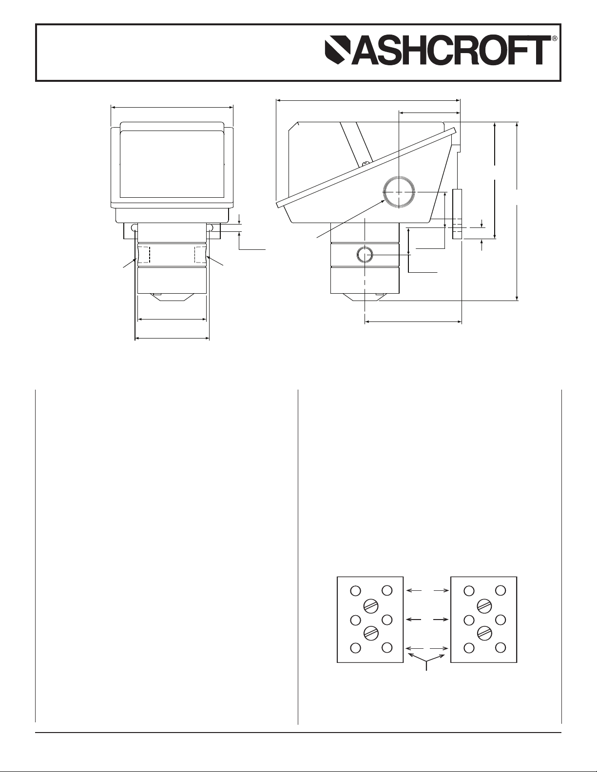
MOUNTING
The “L”Series ASHCROFT®snap action differential pressure
switch has a NEMA-4X enclosure which is an epoxy coated
aluminum casting.
Two holes in the integral bracket are used to surface mount
the control.
Location of these holes is shown on the gener
dimension drawings.An optional pipe mounting bracket is also
available. Mount on a vibration free surface or pipe in any
ientation.
or
PRESSURE CONNECTIONS
For operation as a differential pressure control – connect the
high pressure to the side port marked “H” and the low pressure
to the side port marked “L.”
2007 Ashcroft Inc., 250 East Main Street, Str
©
All sales subject to standard terms and conditions of sale. I&M009-10016-10/00 (250-2871) AMR 12/07
4.1 lbs.
STANDARD RANGES
30, 60, 90, 200, 400 psid
CONDUIT CONNECTIONS
One 3⁄
4 NPT hole fitted with a shipping plug, and two additional
knock outs are provided. The knockouts may be removed by
placing a screwdriver in the slot and rapping sharply with a
hammer.It is recommended that Teflon tape or other sealant be
used on conduit bushing or plug threads to ensure integrity of
the enclosure.
ELECTRICAL CONNECTION
Remove cover, held in place by two screws.
On all units except one with terminal blocks – wire directly to
the switch according to circuit requirements.Units with terminal
locks – wire directly to ter
b
are mar
closed (NC).
al
atford, CT 06614-5145, USA, Tel: 203-378-8281, Fax: 203-385-0499, www.ashcroft.com
ked common (C), normally open (NO) and normally
minal blocks as required.Terminals
Page 2
Installation and Maintenance Instructions
A
B
0
20
40
60
0
20
40
60
for ASHCROFT®L-Series Snap Action
Switches for Differential Pressure Control
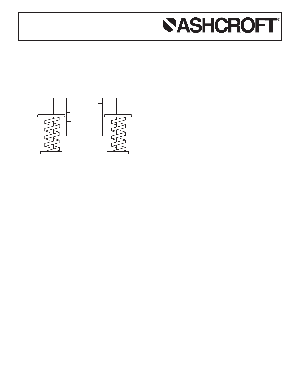
SETPOINT ADJUSTMENTS
Setpoints are changed by means of the setpoint adjusters.The
LD-S single switch has one adjuster and the LD-A adjustable
deadband and LD-D dual switches each have two adjusters. On
witches with two adjusters, the one on the left is referred to as
s
A” and the right one is referred to as “B”; see illustration.
“
etpoints can be adjusted from 20 to 100 percent of full range
S
on increasing pressure.
SERIES LD-S SINGLE SWITCH
Remove cover.For setpoint adjustment on either increasing or
decreasing pressure to within ±1% of nominal range, mount the
switch on a calibration stand and use a suitable reference such
as an ASHCROFT® Duragauge or test gauge. Monitor switch
with a light or meter.
Apply
Low pressure. Then apply High pressure equal to the
low pressure plus the differential pressure setpoint. If setpoint is
on increasing differential pressure, turn adjuster so that switch
operates (if common-normally closed circuit is being monitored
light goes off). If setpoint is on decreasing differential pressure,
turn adjuster so that switch resets (if common – normally closed
circuit is being monitored light comes on).When the setpoint
has been achiev
ed, raise and lower the high pressure to ensure
that the setpoint is correct.
The deadband (difference between the operate and reset
pressures) may be verified at this time to be between the values
noted on the nameplate label.
ERIES LD-D DUAL SWITCH
S
emove cover.For setpoint adjustment to within ±1% of nominal
R
range, mount the switch on a calibration stand and use the suitable reference such as an ASHCROFT
®
Duragauge or test
gauge. Monitor switch with a light or meter.
Apply
Low pressure. Then apply High pressure to the higher
of the two required setpoints.Turn adjuster “B” until the
switch operates or resets as required.See discussion of
ncreasing or decreasing differential pressure setpoints and
i
eadband verification under Series LD-S Single Switch.When
d
he setpoint has been achieved, raise and lower the
t
igh
H
pressure.Then reduce the High pressure to the lower setpoint
differential pressure and turn adjuster “A” until the switch operates or resets as required.Verify this setpoint by raising and
lowering the
High pressure.Now increase the High pressure to
the higher setpoint and make final adjustment on “B.”
SERIES LD-A ADJUSTABLE DEADBAND SWITCH
Remove cover.Adjuster “B”controls the operating point of the
switch on increasing pressure.Adjuster “A”controls the re-setpoint of the switch on decreasing pressure.
For accurate setpoint adjustment, mount the switch on a calibration stand and use a suitable reference such as an
ASHCROFT
light or meter.Apply
®
Duragauge or test gauge.Monitor switch with a
Low pressure. Then apply High pressure to
the required setpoint pressure.
Turn adjuster “B” until switch operates.Then lower differential
pressure to the re-setpoint and turn adjuster “A” until the switch
resets.Now increase pressure to the operating point and make
final adjustment on “B”.Raise and lower pressure to ensure that
the setpoint and re-setpoint are correct.
SOME PRECAUTIONS TO OBSERVE
Do not loosen the screws holding the precision switch
element(s) or mounting bracket in place.
Nameplate
PROOF pressure should not be exceeded.
Intermittent operation up to proof pressure is permissible, however, some change of setpoint may be noted.
Operation and correct setpoint actuation should be routinely
tested.
© 2007 Ashcroft Inc., 250 East Main Street, Stratford, CT 06614-5145, USA, Tel: 203-378-8281, Fax:203-385-0499, www.ashcroft.com
All sales subject to standard ter
ms and conditions of sale
I&M009-10016-10/00 (250-2871) AMR 12/07
.
 Loading...