

Page 1
Data Sheet
G & L-Series Pressure Switches
FEATURES
Precision SPDT or DPDT snap-acting micro switch
Setpoint adjustable from 15-100% of range
Single or dual adjustable set points
Fixed or adjustable deadband
Wide selection of switch elements
TYPICAL USES
Refineries
Chemical and petrochemical plants
Pulp and paper mills
Power plants
Steel mills
Water and sewage treatment plants
Pumps, compressors and turbines
Dairies and breweries
Boilers and burners
Reverse osmosis systems and filters
Filters and presses
Paint spraying equipment
Specialized OEM equipment
Pharmaceutical plants
SPECIFICATIONS
Set Repeatability
(Accuracy):
Switch Type: SPDT or 2 SPDT with independent setpoints,
Setpoint: Single setpoint, fixed deadband
Deadband: Fixed or adjustable deadband
Enclosure Ratings: G Series - NEMA 4X, IP66
Enclosure Material: G Series - 316L Stainless steel
Process Connection: ¼ NPT Female, ½ NPT Female,
Electrical Termination: ¾ NPT Female
APPROVALS
Watertight: L Series - UL, CSA, FM, CE, RoHS, CRN
±1% of span (Additional setpoint shift of
±1% of range per 50°F from initial setpoint
set at 70°F typical)
or 2 SPDT acting as DPDT (X2C)
Single setpoint, adjustable deadband
Independent setpoint, fixed deadband
L Series - NEMA 4X, IP66
L Series - Epoxy coated aluminum
¼ NPT Female and ½ NPT Male Combination
G Series - UL, CSA, CE, RoHS, CRN
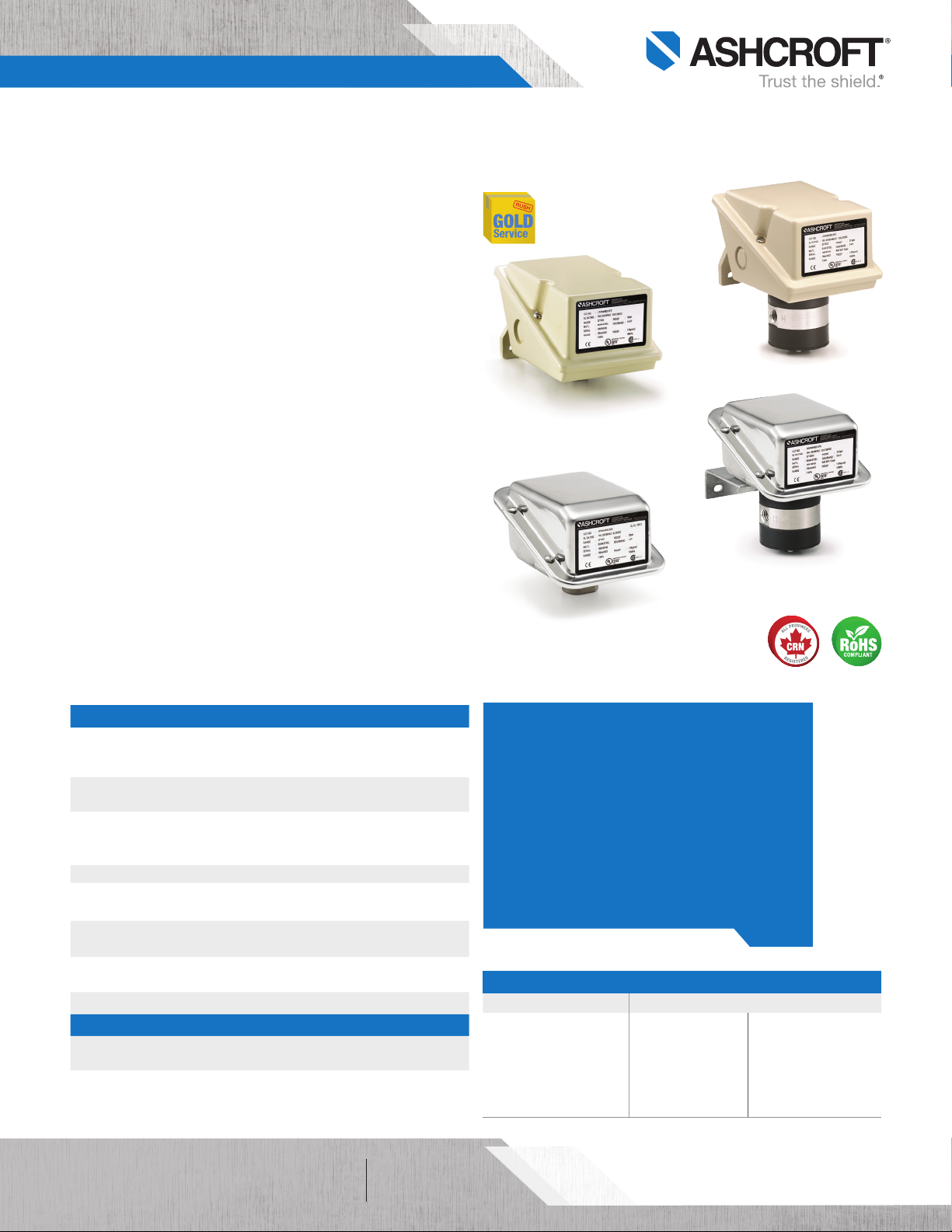
L-Series
Watertight Enclosure
Differential Pressure Switch
L-Series
Watertight Enclosure
Pressure Switch
G-Series
Watertight Enclosure
Differential Pressure Switch
G-Series
Watertight Enclosure
Pressure Switch
KEY BENEFITS
• 316L SS (G-Series) or epoxy-coated aluminum
(L-Series) enclosures provide added protection
in harsh environments
• Designed for use in wide range of applications
• Easily configurable to meet your application
requirements
• Hermetically sealed micro switches offer
improved reliability and safety (UL Class I Div II
approval)
WETTED COMPONENTS
Actuator Seal
Buna-N®, Teflon®, Viton®,
316L SS, or Monel
®
Pressure Switches
316L SS or Monel®
for psi ranges
Epoxy coated carbon
steel or 316L SS for
Process Connection:
Differential Switches
Nickel plated brass or
316L SS for psid ranges
Epoxy coated carbon
steel or 316L SS for
IW ranges
IWD ranges
All speci fications are subject to change without notice.
All sales subject to standard terms and conditions.
©2018 Ashcroft Inc. glseries_p_switch_ds1.0, Rev. B, 07/19
of 61
ashcroft.com
info@ashcroft.com
1.800.328.8258
Page 2
Data Sheet
G & L-Series Pressure Switches
ORDERING CODE Example: GPSN4 G S 25
Enclosure – Pressure Switch
GPSN4 - Single setpoint, fixed deadband, N4 - NEMA 4, 4X, IP66 GPSN4
GPAN4 - Single setpoint, adjustable deadband, N4 - NEMA 4, 4X, IP66
GPDN4 - Two independent adjustable setpoints, fixed deadband, N4 - NEMA 4, 4X, IP66
LPSN4 - Single setpoint, fixed deadband, N4 - NEMA 4, 4X, IP66
LPAN4 - Single setpoint, adjustable deadband, N4 - NEMA 4, 4X, IP66
LPDN4 - Two independent adjustable setpoints, fixed deadband, N4 - NEMA 4, 4X, IP66
Enclosure – Differential Pressure Switch
GDSN4 - Single setpoint, fixed deadband, N4 - NEMA 4, 4X, IP66
GDAN4 - Single setpoint, adjustable deadband, N4 - NEMA 4, 4X, IP66
GDDN4 - Two independent adjustable setpoints, fixed deadband, N4 - NEMA 4, 4X, IP66
LDSN4 - Single setpoint, fixed deadband, N4 - NEMA 4, 4X, IP66
LDAN4 - Single setpoint, adjustable deadband, N4 - NEMA 4, 4X, IP66
LDDN4 - Two independent adjustable setpoints, fixed deadband, N4 - NEMA 4, 4X, IP66
Switch Elements For Single Setpoint with Adjustable Deadband - UL/CSA Listed
H - General purpose, 10A - 125/250 Vac. 1⁄2 A, 125Vdc, 1⁄4 A, 250Vdc
J - Hermetically sealed, general pupose - 11A, - 125/250 Vac, 5A, 30Vdc
Single/Dual Switch Setpoint with Fixed Deadband - UL/CSA Listed
C/CC - Heavy duty ac, 22A - 125/250 Vac
F/FF - Sealed environment proof, 15A - 125/250 Vac. (estimated dc rating - 4A, 28Vdc, not UL listed)
G/GG - General purpose, 15A - 125/250/480 Vac, 1⁄2 A - 125 Vdc, 1⁄4 A - 250 Vdc (not listed at
H/HH - General purpose, 10A - 125/250 Vac 10A, Vdc (P series only)
J/JJ - Hermetically sealed switch, general purpose, 11A, 125/250 Vac, 5A, 30 Vdc
K/KK - Narrow deadband, 15A - 125/250 Vac. (estimated dc rating, 0.4A, 120 Vdc, not UL listed)
L/LL - Hermetically sealed switch, gold contacts, 1A - 125 Vac
M/MM - Low level (gold) contacts, 1A - 125 Vac
P/PP - Hermetically sealed AC - 5A, 125/250 Vac. (estimated dc rating - 2.5A, 28Vdc, not UL listed)
S/SS - Heavy duty dc, 10A - 125 Vac or dc, 1⁄8 HP - 125 Vac or dc.
U/UU - Manual reset actuates on increasing pressure 15A, 125/250 Vac, 6A, 130Vdc
Y/YY - High temperature 300°F (148°C) ambient, 15A, 125/250 Vac
W/WW - Ammonia service - 5A, 125/250 Vac, 6A, 30 Vdc
Actuator Seal
Temperature Limits
Material Ambient Process
B - Buna-N®-20°F to 150°F 0°F to 150°F
V - Viton
T - Teflon®-20°F to 150°F 0°F to 150°F
S - 316L SS -20°F to 150°F 20°F to 300°F
P - Monel®-20°F to 150°F 20°F to 300°F
Process Connections
25 - 1⁄4 NPT Female 25
06 - 1⁄4 NPT Female and 1⁄2 NPT Male combination
07 - 1⁄2 NPT Female
Options - Select from Table 4 on page 4 (If choosing an option(s) must include an “X’’) X _ _
6B - Cleaned for oxygen service 6B
Pressure Range (select from pressure range table on page 3)
100# - 100 psi 100#
®
-20°F to 150°F 20°F to 300°F
Not available in vacuum, & inches of water ranges or
pressures above 1,000 psi
Not available in vacuum, & inches of water ranges or
pressures above 1,000 psi
480 Vac)
G
S
X6B
100#
All speci fications are subject to change without notice.
All sales subject to standard terms and conditions.
©2018 Ashcroft Inc. glseries_p_switch_ds1.0, Rev. B, 07/19
of 62
ashcroft.com
info@ashcroft.com
1.800.328.8258
Page 3

Data Sheet
G & L-Series Pressure Switches
TABLE 1 - PRESSURE/VACUUM RANGES Approximate Deadband Switch Element for Buna-N
See multiplier TABLE 3 for additional material multipliers
Switch Element
Nominal Ranges
Vacuum
Overpressure
Ratings
Proof#
Minimum
Burst psi
LPA-GPA LPS-GPS LPD-GPD
J, H G J, H K, F P GG JJ, HH KK, FF PP
®
Diaphragm
30IMV –760 mmHg 250 400 6-24 2.5-4 6-24 1-2 1-2.5 3-5.5 4-6.5 1-2 1-2.5
Compound
30IMV/
15#
Pressure
–760 mmHg/
1.0 kg/cm
2
250 400
6-24
3-12
2.5-4
1-2.5
4-6
1-3.5
1-2
0.5-1.5
1-2.5
0.5-2
3-5.5
1.5-5.5
4-6.5
1.5-4
1-2
1-2
30IW 750 mmH2O 20 35 4.0-27 1.5-3.5 2.0-4.0 0.5-1.0 0.7-2.0 2.1-4.9 2.8-5.6 0.7-1.4 0.7-2.8
60IW 1,500 mmH2O 20 35 5.0-54 1.5-4.0 2.5-5.0 0.5-1.4 1.0-2.5 3-5.6 3.5-7.0 0.7-2.0 2-3.5
100IW 2,500 mmH2O 20 35 8.5-90 2.0-5.5 4.0-8.5 1.0-2.0 1.4-3.0 4-7.7 5.6-11.7 1.4-2.8 1-4.2
150IW 3,750 mmH2O 20 35 18-135 5.0-11 10-18 1.5-3.0 2.0-6.0 7.0-16 14-25.1 2.1-4.2 5-9.2
70 kg/cm
2
2
2
2
2
2
2
2
500 1,500 2.5-13 1.0-1.5 1.0-2.5 0.5-1.0 0.75-1.5 1.4-2.1 1.4-3.5 0.7-1.4 1-1.4
500 1,500 3.0-27 1.0-2.8 1.0-3.2 0.75-1.5 1-1.8 1.4-5 3-6 1-2.1 1.4-2.5
500 1,500 5-54 2.0-4.0 2.0-4.5 1.0-2.0 1.0-2.5 3-7 4-8 1.4-2.8 1.4-3.5
1,000 3,000 10-90 3-6 5.0-10 1.0-2.5 1.4-3.2 7-12 7.0-14 1.4-3.5 3-7
1,000 3,000 18-180 7-14 10-18 1.0-4.0 5.0-8.0 10-23 14-25 1.4-5.6 7.0-11.2
2,400 3,000 45-360 16-30 16-45 4.0-8.0 5.0-15 22-42 22-63 5.6-11.2 7.0-21
2,400 3,000 75-540 16-50 20-75 5.0-15 6.0-25 22-70 28-105 7.0-21 8.0-35
(1)
12,000
2
12,000 14,000 350-1,800 150-200 150-350 20-50 25-110 209-279 209-488 28-70 35-154
2
12,000 14,000 400-2,600 180-250 180-400 30-70 30-190 251-349 251-558 42-98 42-226
Static #
14,000 160-900 75-130 50-160 7.0-30 10-85 70-180 70-223 10-42 14-119
®
Diaphragm
Overpressure
Ratings
Minimum
Proof #
LDA-GDA LDG-GDA LDG-GDA
J, H G J, H K, F P GG JJ, HH KK, FF PP
See multiplier TABLE 3 for additional material multipliers
Switch Element
15# 1.0 kg/cm
30# 2.0 kg/cm
60# 4.0 kg/cm
100# 7.0 kg/cm
200# 14 kg/cm
400# 28 kg/cm
600# 42 kg/cm
(1)
1000#
2000# 140 kg/cm
3000# 210 kg/cm
(1) Proof pressure is 4,000 psi with SS and Monel® welded diaphragms
TABLE 2 - DIFFERENTIAL PRESSURE RANGES Approximate Deadband Switch Element for Buna-N
Nominal Ranges
Differential Pressure
30IWD –760 mmHg 5.4 21.6 4.0-27 1.3-3.5 2.0-4.0 0.5-1.0 0.7-2.0 2.1-4.9 2.8-5.6 0.7-1.4 0.7-2.8
60IWD 1,500 mmH2O 5.4 21.6 5.0-54 1.5-4.0 2.5-5.0 0.5-1.4 1.0-2.5 3-5.6 3.5-7.0 0.7-2.0 2-3.5
100IWD 2,500 mmH2O 5.4 21.6 8.5-90 2.0-5.5 4.0-8.5 1.0-2.0 1.4-3.0 4-7.7 5.6-11.7 1.4-2.8 1-4.2
150IWD 3,750 mmH2O 5.4 21.6 18-135 5.0-11 10-18 1.5-3.0 2.0-6.0 7.0-16 14-25.1 2.1-4.2 5-9.2
30#D 2.0 kg/cm
60#D 4.0 kg/cm
200#D 14 kg/cm
400#D 28 kg/cm
2
2
2
2
500 1,500 3.0-27 1.0-2.8 1.0-3.2 0.75-1.5 1-1.8 1.4-5 3-6 1-2.1 1.4-2.5
500 1,500 5-54 2.0-4.0 2.0-4.5 1.0-2.0 1.0-2.5 3-7 4-8 1.4-2.8 1.4-3.5
1,000 3,000 18-180 7-14 10-18 1.0-4.0 5.0-8.0 10-23 14-25 1.4-5.6 7.0-11.2
2,400 3,000 45-360 16-30 16-45 4.0-8.0 5.0-15 22-42 22-63 5.6-11.2 7.0-21
1-2.5
1-2
TABLE 3 - DEADBAND MULTIPLIER TABLE
Diaphragm Material Multiply Notes
®
Buna-N
Viton
Teflon
®
®
1.0
1.4
1.7
Multiplier table for additional
316 SS 1.7
®
Monel
All speci fications are subject to change without notice.
All sales subject to standard terms and conditions.
©2018 Ashcroft Inc. glseries_p_switch_ds1.0, Rev. B, 07/19
1.7
diaphragm materials
of 63
ashcroft.com
info@ashcroft.com
1.800.328.8258
Page 4

Data Sheet
G & L-Series Pressure Switches
TABLE 4 - OPTIONS
Code Description
Chained cover • • • • • •
CH
FP Fungus proofing • • • • • •
Factory adjusted setpoints (Supply static pressure
FS
for D/P switches)
G
Series
• • • • • •
L
Series
Pressure
psi inH2O psid inH2O
Differential
Pressure
Gas ⁄ Oil
G5
UL Limit control to 150 inH2O
• •
(LDS only)
Gas ⁄ Oil
G6
UL Limit control to 600 psi
(LDS only)
Steam limit control to 600 psi
G8
(UL listed steam control)
Fire safe actuator
G9
High operating pressure for inH2O ranges
• • •
• •
• •
40 psi Static (Pressure and D ⁄ P)
HX
100 psi Proof (Pressure)
• • • •
160 psi Proof (D ⁄ P)
JL ¾˝ to ½˝ Reducing bushing • • • • • •
K3 Terminal blocks • • • • • •
NH Tagging Stainless steel • • • • • •
PK Pilot lights • • • • •
¾˝ Sealed conduit connection
PM
with 16˝ lead wires
TA
316 SS pressure connection for H2O ranges
UD 316 SS Pressure Connection for psid ranges • • •
2C DPDT with Single Setpoint Adjustment • • • • • •
6B Cleaned for oxygen service • • • •
FM FM Approval (includes pilot lights) • • • • •
Y53A 1½˝ Sanitary seal with glycerin fill with 3A Approval • •
Y63A 2˝ Sanitary seal with glycerin fill with 3A Approval • • •
HS High static operating pressure for psi range D/P • • •
• • • • • •
• • • •
All speci fications are subject to change without notice.
All sales subject to standard terms and conditions.
©2018 Ashcroft Inc. glseries_p_switch_ds1.0, Rev. B, 07/19
of 64
ashcroft.com
info@ashcroft.com
1.800.328.8258
Page 5

PRESSURE
Data Sheet
G & L-Series Pressure Switches
L-SERIES DIMENSIONS in [ ] are millimeters
For reference only, consult Ashcroft for specific dimensional drawings
PRESSURE SWITCH – PSI RANGES
4.12
[105]
3.98
[101]
0.43
[11]
2.25
[57]
2.50
[64]
0.25
[6]
PRESSURE PORT
1
/4 NPT FEMALE
3
/4 NPT
DIFFERENTIAL PRESSURE SWITCH –
PSI DIFFERENTIAL RANGES
4.12
[105]
0.25
3
/4 NPT
1
/4 NPT
FEMALE
HIGH
PORT
L
H
Ø 2.31
[59]
2.50
[64]
[6]
1
/4 NPT
FEMALE
LOW
PRESSURE
PORT
6.09
[155]
X06
1
/2 NPT MALE &
1
/4 NPT FEMALE
6.09
[155]
PRESSURE SWITCH –
INCHES OF WATER RANGES
2.06
[52]
3.94
[100]
0.38
4.72
[120]
[10]
1.21
[31]
3.26
[83]
4.12
[105]
Ø 5.12
[130]
3
/4 NPT
1
/4 NPT
FEMALE
6.09
[155]
2.06
[52]
3.94
[100]
4.65
[118]
0.38
[10]
1.21
[31]
3.26
[83]
DIFFERENTIAL PRESSURE SWITCH –
INCHES OF WATER RANGES
4.12
Ø 5.12
[130]
[105]
[89]
1
4
/
NPT HIGH
1.75
[44]
3.5
PRESSURE
2.06
[52]
3.94
[100]
6.02
[153]
1.21
[31]
0.38 [10]
0.91
[23]
3.26
[83]
1
4
/
NPT LOW
PRESSURE
PORT
3
4
/
NPT
PORT
6.09
[155]
3.26
[83]
1.21
[31]
2.06
[52]
0.38
[10]
3.94
[100]
5.33
[135]
All speci fications are subject to change without notice.
All sales subject to standard terms and conditions.
©2018 Ashcroft Inc. glseries_p_switch_ds1.0, Rev. B, 07/19
of 65
ashcroft.com
info@ashcroft.com
1.800.328.8258
Page 6

Data Sheet
G & L-Series Pressure Switches
G-SERIES DIMENSIONS in [ ] are millimeters
For reference only, consult Ashcroft for specific dimensional drawings
PRESSURE SWITCH – PSI RANGES PRESSURE SWITCH –
INCHES OF WATER RANGES
5.68
4.78
[121]
2.64
[67]
0.25
[6]
3
/4 NPT FEMALE
CONDUIT ADAPTER
X06 VARIATION:
1
2.26
[57]
2.50
[64]
/2 NPT MALE &
1
/4 NPT FEMALE
[144]
1.60
[41]
2.10
[53]
4.13
[105]
1.86
[47]
3.50
[89]
4.17
[106]
0.38
[10]
1
/4 NPT FEMALE
4.78
[121]
2.64
[67]
1.75
3.50
[89]
5.12
Ø
[130]
3
/4 NPT FEMALE
CONDUIT ADAPTER
5.68
[144]
1.60
[41]
2.10
[53]
4.53
[115]
4.17
[106]
1.86
[47]
3.48
[88]
0.38
[10]
DIFFERENTIAL PRESSURE SWITCH –
PSI DIFFERENTIAL RANGES
4.78
[121]
2.64
[67]
3
/4 NPT FEMALE
CONDUIT ADAPTER
L
1
/4 NPT
FEMALE
HIGH
PRESSURE
PORT
H
Ø2.31
[59]
2.50
[64]
1
/4 NPT
FEMALE
LOW
PRESSURE
PORT
0.25
[6]
[144]
DIFFERENTIAL PRESSURE SWITCH –
INCHES OF WATER RANGES
5.68
1.60
[41]
2.10
[53]
1.93
[49]
4.17
[106]
5.61
0.38
[142]
[10]
0.15
[4]
3.48
[88]
1
/4 NPT FEMALE
LOW PRESSURE PORT
4.78
[121]
3.50
[89]
Ø 5.12
[130]
2.64
[67]
3
/4 NPT FEMALE
1.75
[44]
CONDUIT ADAPTER
5.68
[144]
1
/4 NPT FEMALE
HIGH PRESSURE PORT
1.60
[41]
2.10
[53]
4.89
[124]
4.17
[106]
1.86
[47]
3.48
[88]
0.38
[10]
All speci fications are subject to change without notice.
All sales subject to standard terms and conditions.
©2018 Ashcroft Inc. glseries_p_switch_ds1.0, Rev. B, 07/19
of 66
ashcroft.com
info@ashcroft.com
1.800.328.8258
 Loading...