

Page 1

KS SANITARY
1000
750
500
250
0
0362010
1182
30
Load Limitations 4-20mA Output Only
(R
LOOP
)
PRESSURE TRANSDUCER
INSTRUCTION SHEET
WARNING! READ
m m
BEFORE INSTALLATION
1. GENERAL:
A failure resulting in injury or damage
may be caused by excessive overpressure, excessive vibration or pressure
pulsation, excessive instrument temperature, corrosion of the pressure containing parts, or other misuse. Consult
Ashcroft Inc., Stratford, Connecticut,
USA before installing if there are any
questions or concerns.
2. OVERPRESSURE:
Pressure spikes in excess of the rated
overpressure capability of the transducer may cause irreversible electrical and/
or mechanical damage to the pressure
measuring and containing elements.
Fluid hammer and surges can destroy
any pressure transducer and must always be avoided. A pressure snubber
should be installed to eliminate the damaging hammer effects. Fluid hammer
occurs when a liquid flow is suddenly
stopped, as with quick closing solenoid
valves. Surges occur when flow is suddenly begun, as when a pump is turned
on at full power or a valve is quickly
opened.
Liquid surges are particularly damaging to pressure transducers if the pipe
is originally empty. To avoid damaging
surges, fluid lines should remain full (if
possible), pumps should be brought
up to power slowly, and valves opened
slowly. To avoid damage from both fluid
hammer and surges, a surge chamber
should be installed.
Symptoms of fluid hammer and surge's
damaging effects:
• Pressure transducer exhibits an output
at zero pressure (large zero offset).
• Pressure transducer output remains
constant regardless of pressure
• In severe cases, there will be no output.
FREEZING:
Prohibit freezing of media in pressure port.
Unit should be drained (mount in vertical
position with electrical termination upward)
to prevent possible overpressure damage
from frozen media.
3. STATIC ELECTRICAL CHARGES:
Any electrical device may be susceptible to
damage when exposed to static electrical
charges. To avoid damage to the transducer observe the following:
• Ground the body of the transducer
BEFORE making any electrical
connections.
• When disconnecting, remove the ground
LAST!
Note: The shield and drain wire in the
cable (if supplied) is not connected to the
transducer body, and is not a suitable
ground.
Mounting
Although the unit can withstand normal vibration without damage or significant output
effects, it is always good practice to mount
the transducer where there is minimum
vibration. Be sure to use a gasket that does
not interfere with the sanitary diaphragm. If
the gasket I.D. is smaller than 1.50 inches,
an offset due to clamping force will occur.
Power Supply
The supply voltage for the 1-5 and
1-6 Vdc output transducers must be within
the range of 10 to 36 Vdc. The maximum
supply voltage for a 4-20mA current output
transducer is 36 Vdc while the minimum
supply voltage is dependent upon the loop
resistance of the circuit. The Load Limitation Chart shows the minimum supply
voltage (V
resistance (R
) required for a given loop
min
).
LOOP
Excitation (Ratiometric Output Only)
For proper operation a voltage within
the range of 5 to 10 Vdc must be
ap plied between the transducer’s supply
terminals.
Noise
For minimum noise susceptibility, avoid
running the transducer’s cable in a conduit that contains high current AC power
cables. Where possible avoid running the
cable near inductive equipment.
Shield Wiring
Connect the braided shield to the guard
terminal on the reading instrument (meter,
etc.) if available or to ground or to the
power supply negative terminal.
Adjustment Potentiometers
The zero and span pots are accessible
through the top of the case. Loosen the
four screws and separate the top carefully.
The zero pot is marked with a white dot.
Vent Tube
The cable will have a clear Teflon vent
tube that's required at pressure below 500
psi to provide atmospheric reference. The
open end should be placed in a dry area.
OPERATING
REGION
V
= 10V+ (.022A x RL)
min
RL = RS + R
RL = Loop Resistance (ohms)
RS = Sense Resistance (ohms)
RW = Wire Resistance (ohms)
W
© 2011 Ashcroft Inc., 250 East Main Street, Stratford, CT 06614, USA • Tel: 203-378-8281, Fax: 203-385-0402 • email: info@ashcrfoft.com, www.ashcroft.com.
All specifications subject to change without notice. All sales subject to standard terms and conditions of sale. I&M011-10124 (250-3110) Rev. A 5/11
Page 2
+
+
–
POWER
SUPPLY
(+)
(–)
METER
TRANSDUCER
–
POWER
OUTPUT
RED
BLACK
+
+
–
–
POWER
SUPPLY
(Common)
(+ Power)
(+ Output)
METER
TRANSDUCER
GREEN
RED
WHITE
+
+
–
–
POWER
SUPPLY
(- Power)
(+ Power)
(- Output)
(+ Output)
METER
TRANSDUCER
RED
WHITE
GREEN
BLACK
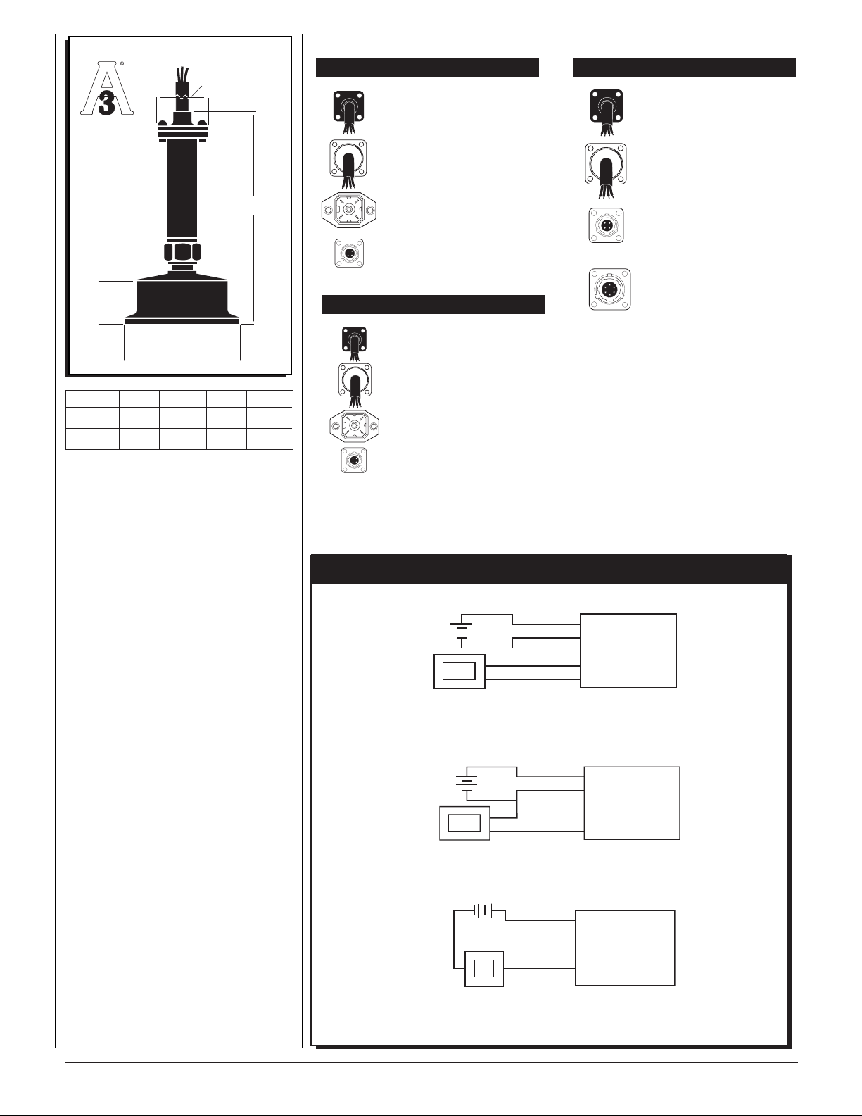
Dimensions
A
▲
▲
▲
B
▲
C
▼
▲
MODEL A B C D
D
S15 0.8 4.7 0.9 2.0
S20 0.8 4.7 0.9 2.5
▼
▲
KS Sanitary Transducers – Electrical Conn.
Voltage Output Units 1-5, 1-6 Vdc
Cable Type F2
Red = + Power
White = Common
Green = Output
Cable Type C1
Red = + Power
White = Common
Green = Output
Hirschmann Type
PIN-1 = + Power
PIN-2 = Common
PIN-4 = Output
Bendix 4-Pin, 6-Pin
Pin A = + Power
Pin B = Output
Pin D = Common
Current Output Units 4-20 mA
Cable Type F2
Red = + Power
Black = – Power
Cable Type C1
Red = + Power
Black = – Power
Hirschmann Type
PIN-1 = + Power
PIN-2 = – Power
Bendix 4-Pin, 6-Pin
Pin A = + Power
Pin B = – Power
Ratiometric (mV/V)
Cable Type F2
Red = + Power
White = – Power
Green = + Output
Black = – Output
Cable Type C1
Red = + Power
White = – Power
Green = + Output
Black = – Output
Bendix 4-Pin
Pin A = +Power
Pin B = +Output
Pin C = – Output
Pin D = – Power
Bendix 6-Pin
Pin A = +Power
Pin D = – Power
Pin B = +Output
Pin C = – Output
Pin E = Shunt Cal.
Pin F = Shunt Cal.
Wiring Diagrams for All Transducers
4-Wire Ratiometric (mV/V)
3-Wire Voltage
© 2011 Ashcroft Inc., 250 East Main Street, Stratford, CT 06614, USA • Tel: 203-378-8281, Fax: 203-385-0402 • email: info@ashcrfoft.com, www.ashcroft.com.
All specifications subject to change without notice. All sales subject to standard terms and conditions of sale. I&M011-10124 (250-3110) Rev. A 5/11
4-20 mA
 Loading...