

Ashcroft KM15 User Manual

KM15 PRESSURE TRANSDUCER
INSTRUCTION SHEET
WARNING! READ
BEFORE INSTALLATION
1. GENERAL:
A failure resulting in injury or damage may be caused by excessive
overpressure, excessive vibration or
pressure pulsation, excessive instrument temperature, corrosion of the
pressure containing parts, or other
misuse. Consult Ashcroft Inc.,
Stratford, Connecticut, USA before
installing if there are any questions
or concerns.
2. OVERPRESSURE:
Pressure spikes in excess of the rated
overpressure capability of the transducer may cause irreversible electri-
cal and/or mechanical damage to the
pressure measuring and containing
elements.
Fluid hammer and surges can destroy
any pressure transducer and must
always be avoided. A pressure snubber should be installed to eliminate the
damaging hammer effects. Fluid hammer occurs when a liquid flow is suddenly stopped, as with quick closing
solenoid valves. Surges occur when
flow is suddenly begun, as when a
pump is turned on at full power or a
valve is quickly opened.
Liquid surges are particularly damaging to pressure transducers if the pipe
is originally empty. To avoid damaging
surges, fluid lines should remain full (if
possible), pumps should be brought up
to power slowly, and valves opened
slowly. To avoid damage from both fluid
hammer and surges, a surge chamber
should be installed.
Symptoms of fluid hammer and surge's
damaging effects:
• Pressure transducer exhibits an output at zero pressure (large zero offset).
• Pressure transducer output remains
onstant regardless of pressure
c
• In severe cases, there will be no output.
FREEZING:
Prohibit freezing of media in pressure
port. Unit should be drained (mount in
vertical position with electrical termination upward) to prevent possible
overpressure damage from frozen
media.
3. STATIC ELECTRICAL CHARGES:
Any electrical device may be susceptible to damage when exposed to static
electrical charges. To avoid damage to
the transducer observe the following:
• Ground the body of the transducer
BEFORE making any electrical connections.
• When disconnecting, remove the
ground LAST!
Note: The shield and drain wire in the
cable (if supplied) is not connected to
the transducer body, and is not a suitable ground.
Mounting
The KM15 transducer requires no special
mounting hardware, and can be mounted
in any plane with negligible position error.
Although the unit can withstand normal
vibration without damage or significant
output effects, it is always good practice
to mount the transducer where there is
minimum vibration.
For units with NPT type pressure fittings
apply Teflon
sealant to the threads before installing.
®
tape or an equivalent
When tightening, apply a wrench to the
hex wrench flats located just above the
pressure fitting. DO NOT tighten by using
a pipe wrench on the housing.
Noise
For minimum noise susceptibility, avoid
running the transducer’s cable in a conduit that contains high current AC power
cables. Where possible avoid running the
cable near inductive equipment.
Shield Wiring
(Cable Termination Only)
Connect the braided shield to the guard
terminal on the reading instrument
(meter, etc.) if available or to ground or to
the power supply negative terminal.
Vent Tube (Cable Termination Only)
The cable will have a clear Teflon
tube that's required at pressure below
500 psi to provide atmospheric reference. The open end should be placed in
a dry area.
Output Type Excitation Supply Current
0.5/4.5 V
Ratiometric
1/5V 8-32 Vdc 10mA typ
Teflon is a registered trademark of E. I. DuPont
RoHS Compliant
5V±.5 Vdc 10mA typ
®
vent
© 2011 Ashcroft Inc., 250 E. Main St., Stratford, CT 06614-5145, Tel: 203-378-8281, Fax: 203-385-0408, www.ashcroft.com
All sales subject to standard terms and conditions of sale.
I&M011-10168. Rev. A 5/11
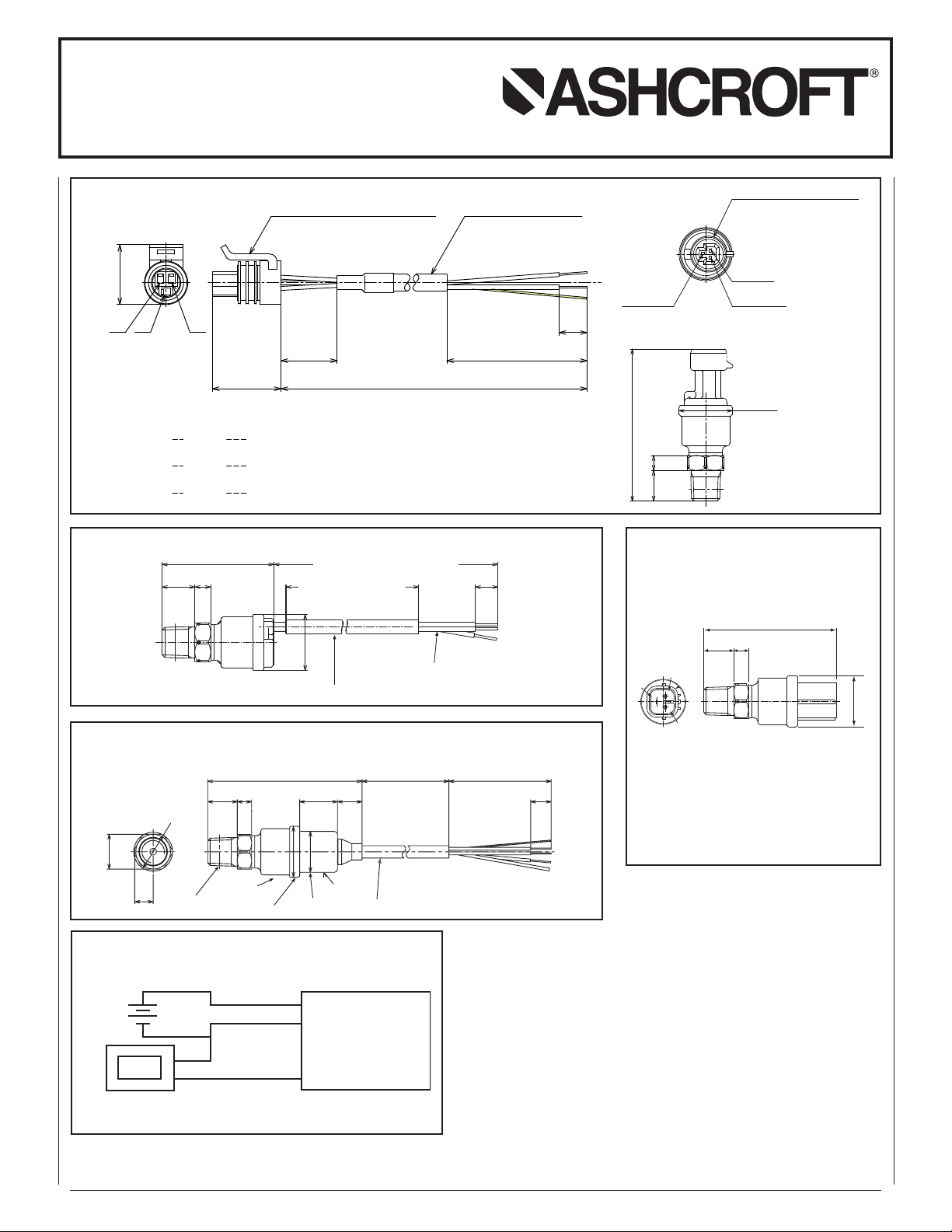
KM15 PRESSURE TRANSDUCER
(10)(7)(14.5)
(25) DIA.
(49.5)
L
ead Length As Specified By Customer
Lead Length Less 50mm (2˝)
.28˝
.58˝
2˝
1˝
Protective Sleeve
Red : Power (+)
White: Output (+)
Black : Common
.
4˝
0.5mm
2
20 A
WG Leads
2 ft.
Standard Length
(25)
DIA.
.57˝ .28˝
(64)
1.00˝
2.5˝
(14.5) (7)
1
2
3
3
2
1
+
+
–
–
POWER
SUPPLY
(Common)
(+ Power)
(+ Output)
METER
TRANSDUCER
METER OR
OTHER DEVICE
(21.3)
(
B) (C) (A)
C
ommon
Power(+)
B
lack
Red(B)
(
A)
M
ETRI-PACK 150 Series SHIELDED CABLE
O
utPut(+)White(C)
MAT ING CONNECTOR
(
20) (50)
(10)
(24.5)
(.84")
(
.97")
(.79")
.
39"
1.97"
L
ead Length As Specified By Customer
OPTIONAL
1
2065287
PIN
METRI-PACK 150 Series
OUTPUT(+)
P
OWER(+)
COMMON
(25 DIA.)
(7)(14.5)
(71.6)
.27".57"
(2.8")
.
98" DIA.
MATE S TO OPTIONAL METRI-PACK
CONNECTOR 12065287
Cab
le
Housing
Fitting
(870) 34
Std.
(10)
( )
(50)
(14.5))(7)
( )
(75.5)
(20) DIA.
.78
(12)
(25) DIA.
.98
(9)
(18.5)
SS Case
.57
.73
3
(
1
9
)
IA
.
(17)
Red :Power (+)
White: Output (+)
Black : Common
.7
5
˝
.
3
5
˝
.
6
7
˝
INSTRUCTION SHEET
METRI-PACK
imension Drawing
D
Dimensions
in ( ) are mm
FLYING LEAD STYLE
Dimension Drawing
Dimensions
in ( ) are mm
SHIELDED CABLE TERMINATION
Dimension Drawing
(Height may vary slightly depending on process connection)
WIRING DIAGRAM FOR ALL KM15 TRANSDUCERS
Dimensions
in ( ) are mm
CONNECTOR STYLE TERMINATION
Dimension Drawing
(Height may vary slightly depending
on process connection)
Dimensions
n ( ) are mm
i
Mating Connector
Mates to HW090 Connector by Sumitomo Wiring
Systems. Made of PBT (polybutylene terephthalate).
Flying Leads : 20AWG, 3 ft. (.9m) standard
PIN Color Function
1 Red Supply (+)
2 White Output (+)
3 Black Common
© 2011 Ashcroft Inc., 250 E. Main St., Stratford, CT 06614-5145, Tel: 203-378-8281, Fax: 203-385-0408, www.ashcroft.com
All sales subject to standard terms and conditions of sale.
3-Wire Voltage
I&M011-10168. Rev. A 5/11
 Loading...