

Page 1
© Ashcroft Instruments Gm bH, Ma x-Planck-Straße 1, D-52499 Baesweiler, Deutschland, Telefon: +49 (0) 2401-808-0, Telefax +49 (0) 2401-7027 www.ashcroft.eu
All sales subject to standard terms and conditions of sale. All rights reserved
IM KM11Ex EN 08/2015 page 1 of 2
KM11 PRESSURE TRANSMITTER
INSTRUCTION SHEET
WARNING! READ
BEFORE INSTALLATION
The ATEX approved pressure
transmitter of Ashcroft KM11 family
are designed to sense pressure in
facilities with gaseous or liquid
media. They are usable in zone 1.
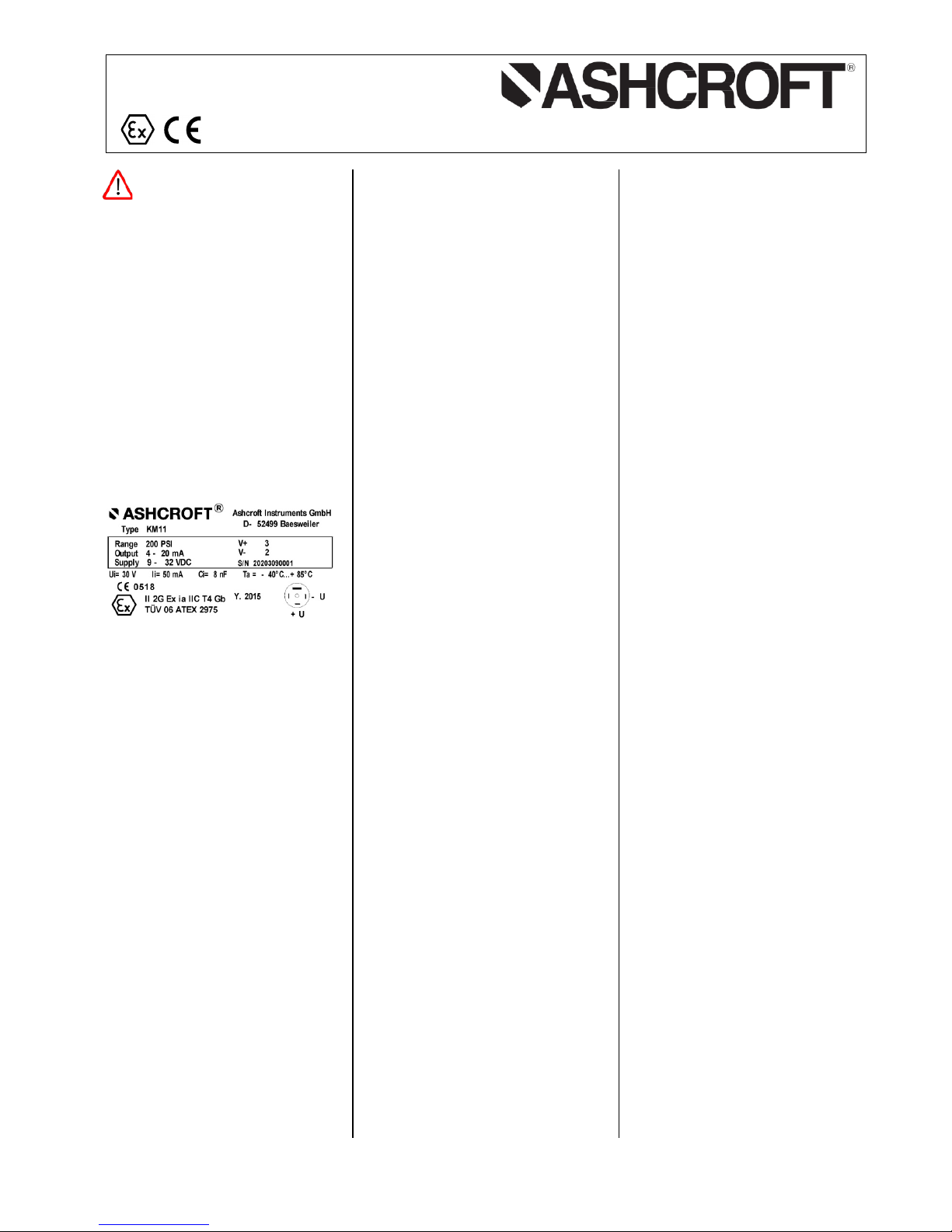
Transmitters are affected with the
approval number
TÜV06ATEX2975
and markings
II 2G Ex ia IIC T4 Gb
-40°C ≤ Ta ≤ 85°C
Label
CONDITIONS GOVERNING THE
USE OF THE PRODUCT
General directions
to be complied with at all times for
correct and safe use of the
electronic pressure transmitter:
• Please keep within the limit
values given in the specification
for such items as pressure, force,
torque and temperature.
• Give due consideration to the
prevailing ambient conditions
(temperature, atmospheric
humidity, atmospheric pressure,
etc.)
• Observe the applicable safety
regulations laid down by the
regulatory bodies in the country of
use.
• Use the product only in its origina l
conditions. Do not carry out any
unauthorized modifications.
• Remove all items providing
protection in transit such as foils,
caps or cartons.
OPERATING CONDITIONS
• Type testing does not apply to all
ambient conditions without
limitations. The user is
responsible for verifying that the
plug-and-socket connection
complies with the specified rules
and regulations, or whether it may
be used for specialized purposes
other than those intended by use.
• The values given in the technical
data for overpressure safety
relate to the hydraulic or
pneumatic part of the pressure
transmitter.
• The EN 60079-0:2012 and
EN 60079-11:2012 standards
were applied.
• Ambient temperature range
-40 °C up to +85 °C
• Medium temperature range
-40 °C up to +85 °C
• Safety related maximum values of
electrical connection:
U
i
30 V DC
I
i
50 mA
C
i
5 nF
L
i
negligible
Consider for connected cable
C
i
= 300 pF/m and Li = 1 µH/m
INSTALLATION
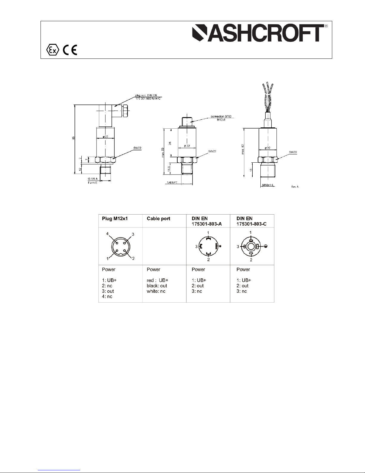
Mechanical / pneumatic /
hydraulic:
• Screw the electronic pressure
transmitter into the press ur e
connection provided using an
open-jaw spanner of 22 AF size
(as per DIN 894 or similar), with a
tightening torque of approx.
25 Nm.
• To seal the system, use a
standard copper seal with the
appropriate dimensions.
Electrical:
• All wiring should conform to local
codes and must be carried out by
authorized personal onl y. Keep
high and low voltage wiring
separated. For applications in
critical industrial environment use
special cables.
• Observe without fail the
connecting information – labeled
on the transmitter or laid down in
the operating instructions – while
connecting the pressure
transmitter.
• Ensure that the cables routed
without crushing.
• Electricity supply and wirings
must be suitable for the demands
of the hazardous area.
• The electricity supply of the
transmitter must occur according
to the regulations for intrinsic
circuits. A security (e.g., glaze)
protection is recommended.
• When allocation is valid with
cable connection:
4-wire ventilated or un vent ilated
cable
red Loop +
black Loop –
white (not connected)
Indication
Pressure is balanced by a micro
filter (in level sensors by a capillary
in the cable) between the trans mitter and the ambient
environment. This allows explosive
mixtures from the ambient
environment to intrude into the
transmitter or it is possible that
mixtures accumulating inside the
transmitter due to diffusion escape
from the housing.
DIMOUNTING
• When disassembling the pressure
system, it must be depressurized.
• Please observe applicable safety
regulations when removing the
pressure transmitter.
DISPOSAL
• Please help to protect the
environment and dispose of or
recycle the devices and
components used in accordance
with the applicable regulations.
Page 2
© Ashcroft Instruments Gm bH, Ma x-Planck-Straße 1, D-52499 Baesweiler, Deutschland, Telefon: +49 (0) 2401-808-0, Telefax +49 (0) 2401-7027 www.ashcroft.eu
All sales subject to standard terms and conditions of sale. All rights reserved
IM KM11Ex EN 08/2015 page 2 of 2
KM11 PRESSURE TRANSMITTER
INSTRUCTION SHEET
General dimensions:
Electrical connection:
nc = not connected
The electrical connection must be made in accordance with the respective connection diagram unless otherwise
agreed upon.
* Custom-made adjustments are available.
 Loading...