

Page 1
Installation and Maintenance Instructions
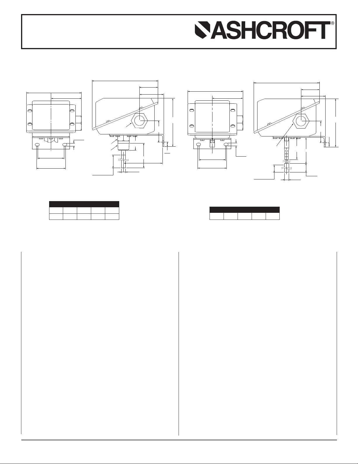
2.64
(67)
4.78
(121)
0.25
(6)
2.26
(57)
2.50
(64)
5.68
(144)
1.60
(41)
2.10
(53)
0.38
(10)
1.31
(33)
3.38
(86)
Ø0 . 37
( 9)
4.17
(106 )
1. 86
(47)
“S”
2. 3 1
ACTIVE BULB
LENGTH
(
59)
7/8 HEX
1
/2 NPT FEMALE
3/4 NPT FEMALE
CONDUIT ADAPTER
2.64
(67)
4.78
(121)
0.25
(6)
2.26
(57)
2.50
(64)
2.31
ACTIVE BLUE
L
ENGTH
(59)
2.50
(64)
“L”
Ø
0.3 7
(9)
3.00
(76 )
2.10
(
53 )
1.6 0
(4 1)
5.68
(144 )
4.17
(106)
0.38
(10)
1
.8 6
(47)
3/4 NPT FEMALE
CONDUIT ADAPTER
for ASHCROFT®G-Series Snap Action
Switches for Temperature Control
Direct Mount
emote Mount
R
3.5 lbs. (1.6kg)
4.5 lbs. (2.0kg)
STEM LENGTH (S)
IN.
23⁄
4 46912
MM
(70) (102) (152) (229) (305)
OPERATION
The ASHCROFT®temperature control is a precision device
which features a snap action switch.Fixed dead band is available
with single or dual SPDT independently adjustable switches with
various electrical ratings.Adjustable deadband is available with
a SPDT switch with various electrical ratings.Bulb material is
stainless steel.
ies GT-S s
Ser
witches have a fixed deadband which will be
within the limits noted on the nameplate.
Series GT-D switches may be set to operate simultaneously or
up to 85 percent of the range apart. The deadband of each
switch will be within the limits noted on the nameplate.
Series GT-A switches may be set to operate with any deadband
within the limits shown on the nameplate.
A. STEM MOUNTED CONTROLS
These controls have a 1⁄
attached directly (or indirectly by means of a thermowell) to
equipment to be controlled.
REMOVING CONTROL ALWAYS USE THE WRENCH
FLATS OR HEX ABOVE THE THREADS.DO NOT TWIST
THE HOUSING.
B. REMOTE MOUNTED CONTROLS
Two types of union bushings are available to install a remotemounted control bulb into a thermowell or other
threaded hole. A non-pressure-tight type consists of a bushing, split grommet and compression nut.To use this, the bulb
is inser
into the capillar
MOUNTING
The “G” Series ASHCROFT®snap action temperature switch
has a NEMA-4X enclosure which is made of 316 stainless steel.
k
o holes in the br
w
T
the control. Location of these holes is shown on the general
dimension drawings.An optional pipe mounting bracket is also
available. Mount on a vibration free surface or pipe in any
ac
et supplied are used to surface mount
orientation.
Good piping practice requires the use of a well for installation,
where pressure ma
y be applied to the ther
mal system, for protection against physical damage as well as corrosive effects of
media flow. Use of a well also facilitates removal of the bulb
from the process line without disturbing the process
well materials include brass, steel and stainless steel; other materials are available on application.Selection should be based on
corrosion resistance requirements and process pressure.
© 2007 Ashcroft Inc., 250 East Main Street, Stratford, CT 06614-5145, USA, Tel: 203-378-8281, Fax: 203-385-0499, www.ashcroft.com
All sales subject to standard ter
ms and conditions of sale
I&M009/10022-10/00 (250-2894) AMR 12/07
.
.
Standard
ings. After positioning the bulb as desired, tighten the compression nut to the b
desired location.The pressure-tight type is clamped to the
bulb after insertion by tightening a compression nut.To use
this, the union bushing is screwed into the 1⁄
hole.The compression nut and sleeve are slipped onto the
bulb which is then inserted into the union bushing. Bulb is
then positioned and compression n
2
CONDUIT CONNECTIONS
One 3⁄
It is recommended that Teflon tape or other sealant be used on
conduit bushing or plug threads to ensure integrity of the
enclosure.
LINE LENGTH
FT.
5 10 15 20 25
ted through the nut and the split g
y between the compression nut and the bush-
1
⁄
2 turns. This will lock the bulb at the desired location.
4 NPSM conduit adapter of 316 stainless steel is provided.
2 NPT threaded adapter and may be
WHEN INSTALLING OR
1
⁄
2 NPT
rommet is slipped
This will lock the capillar
ushing.
2 NPT threaded
ut is hand tightened plus
y at the
Page 2
Installation and Maintenance Instructions
A
B
0
20
40
60
0
20
40
60
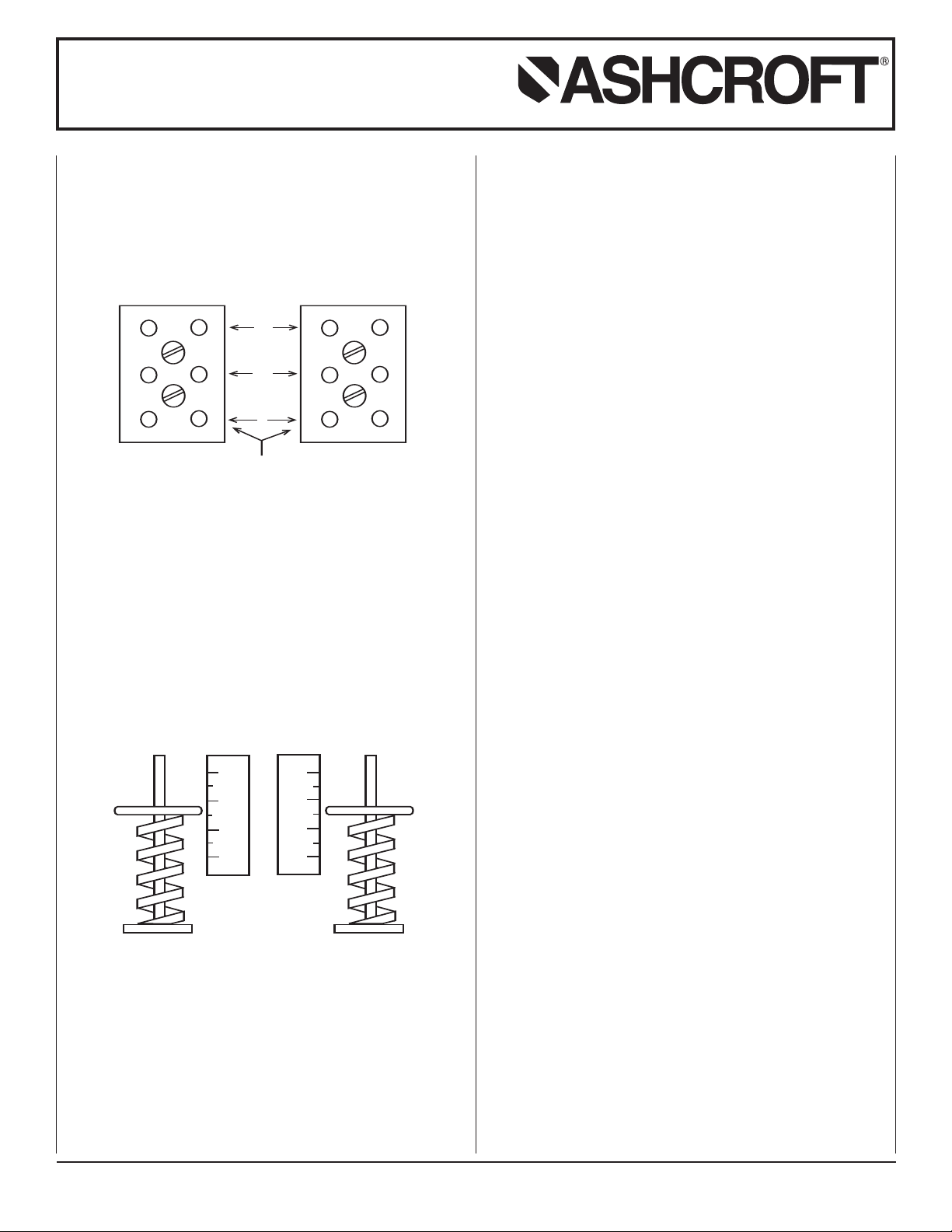
1 2 3
1 2 3
LEFT SWITCH
TERMINAL BLOCK
RIGHT SWITCH
T
ERMINAL BLOCK
SERVICE LEADS TO THESE TERMINALS
NC
NO
C
for ASHCROFT®G-Series Snap Action
Switches for Temperature Control
LECTRICAL CONNECTION
E
Remove cover, held in place by four screws.
On all units except one with terminal blocks – wire directly to
the switch according to circuit requirements.Units with terminal
blocks – wire directly to terminal blocks as required.Terminals
are marked common (C), normally open (NO) and normally
closed (NC).
SETPOINT ADJUSTMENTS
Setpoints are changed by means of the setpoint adjusters.The
GT-S single switch has one adjuster and the GT-A adjustable
dead band and GT-D dual switch each have two adjusters.On
switches with two adjusters, the one on the left is referred to as
“A” and the right one is referred to as “B”;see illustration.
Setpoints can be adjusted from 20 to 100 percent of full range
on increasing temperature.
When adjusting temperature controls optimum performance
will be obtained if the bulb is fully immersed.After initially inserting a bulb into a controlled bath, allow five minutes for stabilization.Whenever setpoint adjustment requires a bath temperature
to be varied (such as to observe setpoint and re-setpoint values)
the rate of change in temperature should not exceed 1 0F per
minute.Switch operation should be monitored with a suitable
light or meter.
SERIES GT-S SINGLE SWITCH
Remove cover.For setpoint adjustment on either increasing or
decreasing temperature, the bulb of the control should be
immersed in a bath at the desired setpoint temperature.Opti-
um performance will be obtained if bulb is fully immersed.
m
llow five minutes for initial stabilization. Monitor switch with a
A
light or meter.
If setpoint is on increasing temperature, turn adjuster so that
switch operates (if common – normally closed circuit is being
monitored light goes off). If setpoint is on decreasing temperature, turn adjuster so that switch resets (if common – normally
closed circuit is being monitored light comes on).When the
setpoint has been achieved, raise and lower the temperature to
ensure that the setpoint is correct.
The deadband (difference between the operate and reset
temperatures) may be verified at this time to be between the
values noted on the nameplate label.
SERIES GT-D DUAL SWITCH
Remove cover.Immerse the bulb and monitor the switch as
described under Series GT-S Single Switch. Also see discussion of increasing or decreasing setpoints and deadband verification.The initial bath temperature should be the higher setpoint.Turn adjuster “B” until the switch operates or resets as
required.When the setpoint has been achieved, raise and lower
the bath temperature to ensure that the setpoint is correct.Then
reduce the bath temperature to the lower setpoint and turn
adjuster “A” until the switch operates or resets as required.
Verify this setpoint by raising and lowering bath temperature.
Now increase the temperature to the higher setpoint and make
final adjustment on “B.”
SERIES GT-A ADJUSTABLE DEADBAND SWITCH
Remove cover.Adjuster “B” controls the operating point of the
switch on increasing temperature.Adjuster “A” controls the resetpoint of the switch on decreasing temperature.
Immerse the bulb and monitor the switch as described under
single switch setpoint adjustment.With the bath at the required
setpoint temperature, turn adjuster “B” until switch operates.
Then lower the bath temperature to the re-setpoint and turn
adjuster “A” until the switch resets. Now increase the temperature to the oper
ating point and make final adjustment on “B.”
Raise and lower temperature to ensure that the setpoint and
re-setpoint are correct.
2007 Ashcroft Inc., 250 East Main Street, Str
©
All sales subject to standard terms and conditions of sale. I&M009/10022-10/00 (250-2894) AMR 12/07
SOME PRECA
Do not loosen the screws holding the precision switch element(s)
or mounting bracket in place.
Nameplate
mittent operation up to proof temper
Inter
however, some change of setpoint may be noted.
ation and correct setpoint actuation should be routinely
Oper
tested.
atford, CT 06614-5145, USA, Tel: 203-378-8281, Fax: 203-385-0499, www.ashcroft.com
UTIONS TO OBSERVE
PROOF temperature should not be e
ature is permissible,
xceeded.
 Loading...