

Page 1
Quick Start Function Summary
Instructions for ASHCROFT
®
GC52 Differential Pressure
Transmitter
Version 6.03 Rev. B
(See Complete I&M Manual for Further Detail)
LOOK FOR THIS
AGENCY MARK ON
OUR PRODUCTS
© 2010 Ashcroft Inc., 250 East Main St., Stratford, CT 06614-5145, USA, Tel: 203-378-8281, Fax: 203-385-0499,
www.ashcroft.com All sales subject to standard terms and conditions of sale.
I&M011-10164-GC52 Ver. 6.03 Rev.B 03/11
Page 2

2
Page 3
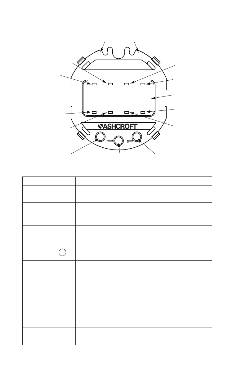
CH+
CH–
GC52
In H2O
M
▼
▲
b
Differential pressure
unit monitor
Test Terminals
d
MODE key
e
DOWN key
f
UP key
c
Scaling - Arbitrary
unit monitor
h No function
a
Measured data
display
8.8.8.8.8.8.
k Total flow volume
display (X100)
l Total flow volume
display (X1000)
g
Linear scaling mode
j Total flow volume
display (X10)
i Total flow volume
display (X1)
DISPLAY OVERVIEW
DESIGNATION FUNCTION
Measured data
display
Differential
pressure unit
monitor
Scaling; arbitrary
unit monitor
MODE key M
DOWN key S
UP key T
Linear scaling
mode
No function
to
volume display
Differential pressure, linear scaling value are displayed.
When this unit monitor is ON, the differential pressure
(in H
O) is indicated on the measured data display.
2
When this unit monitor is ON, the scaling value of an
arbitrary unit (linear scaling), is indicated on the
measured data display.
This key is used to switch the setting mode and the
measurement mode and to change the setting item.
This key is used to change (decrease) and select the
set value.
This key is used to change (increase) and select the set
value and to shift from the measurement mode to the
zero adjustment mode.
Change differential pressures into quantity
Total flow
None
Accumulated volume calculated based on flow rate
3
Page 4
11..
Note: Holding the button for more than
3 seconds returns to display mode.
UPON
POWER-UP the unit enters “Measure Mode” – displaying applied pressure.
22..
O FUNCTION is available to the user in “Measure Mode”.
TW
A. Zero Adjustment Mode: In the measurement mode,
the pressure connection is open to the atmosphere and $key is
pressed for more than 3 seconds in order to shift to zero adjustment
mode for zero point adjustment of the differential pressure sensor
• If the zero point adjustment is performed correctly the message “ADJ”
will be displayed for 2 seconds, and the display will return to the measurement mode.
B. Key Lock
Function Key Manual Indicator
Setting of key lock MODE+
Release of key lock MODE+$one second UnL (Key invalidity)
Operation during keylock
Function Key Manual Indicator
Zero adjust. mode
Hold value reset
33..
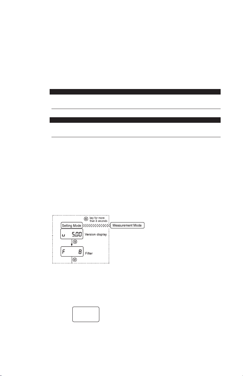
FI
VE FUNCTIONS available to the User via “Setting Mode”. To enter the “Set-
$
#
one second LoC (Key invalidity)
$
key greater than 3 sec LoC (Key invalidity)
key greater than 3 sec LoC (Key invalidity)
ting Mode” hold (M) key for more than 3 seconds.
(See last page for complete Setting Mode menu.)
A. Filter (Damping)
The filter is based on the moving average of the pressure data to decrease display “bounce” and to smooth the analog output due to system
pressure fluctuations at the user’s discretion.
Five selections: (0, 2, 4, 8 and 16 seconds), Use
$#
keys to change value.
If “0” is selected the filter is not applied.
B. Re-scaling in “inH
O” units: “Pressure Display Mode” allows for zero
2
(4mA) and span (20ma) adjustment of –10 to +110% Span respectively.
Note: 1. See menu schematic on last page for detail.
2. Must be in “Pressure Display Mode” option within “Setting Mode,”
this is noted on the screen by
-
n non
Use $#keys to move between “Pressure Display Mode” and
“Linear Display Mode” which is for re-scaling in “Arbitrary” units.
4
Page 5
3. To adjust Output Zero Point (4mA) and Output Span Point
(20mA) the unit must be in the functional area as noted below
while adjustment is via $#keys. The value shown is a percentage of the pressure range (span) as noted on the product label
(ex. If product was supplied as a 0-40 IWC range and the user desired the Output Zero Point (4mA) to be “moved” from 0 IWC to 20
IWC then Output Zero Point would be 50.0 which is 50%.
Values shown below are from I&M manual.
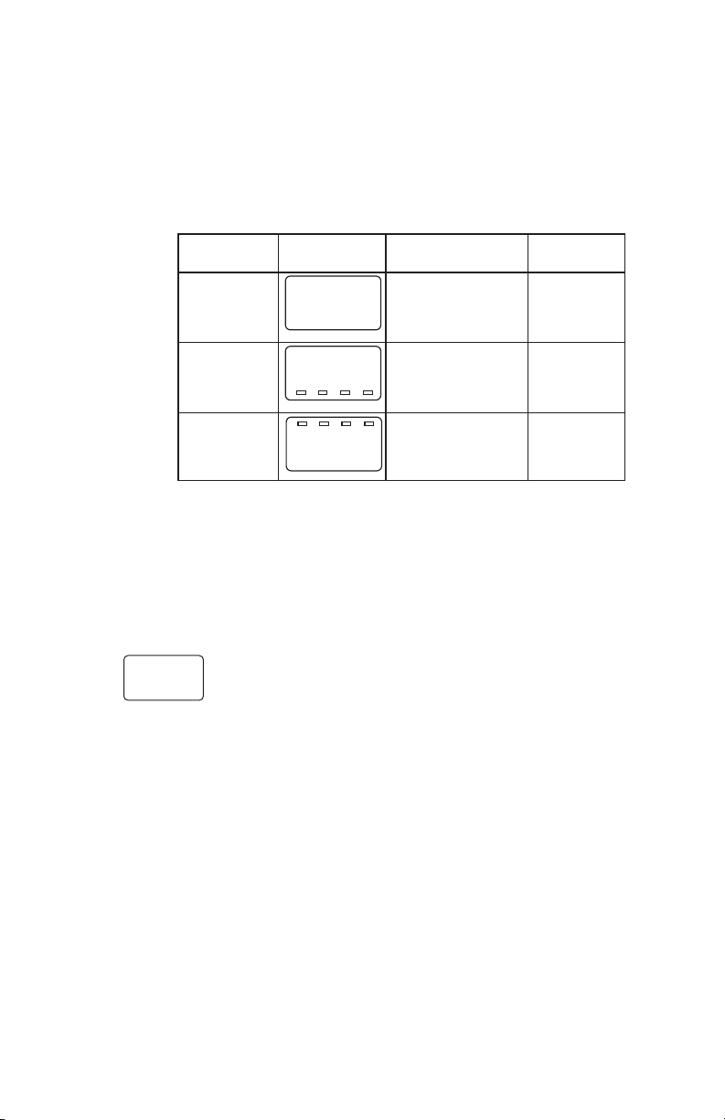
Setting LCD Setting Setting
Item Display Description Range
Display Selection of non:pressure
mode pressure display display mode
Output Analog Pressure
zero point output zero point range:–10
.
Output Analog Pressure
span point output span point range:–10
Note: For setting of zero point and span point in the analog
output, input the percent value over the pressure range.
C. Re-scaling in “Arbitrary” units, “Linear Display Mode.” This function
allows the user to establish a linear relationship from the standard “inH
unit to any user defined unit.
Note: See menu schematic on last page. Unit must be in “Linear Display
Mode” option within “Setting Mode”, this is noted on the screen by
-
n non
a 10.0
a 90.0
mode : non Lin: linear
(4mA) : 10.0 (%Span) to 110% Span
(20mA) : 90.0 (%Span) to 110% Span
display mode
O”
2
-
n L;n
Use $#keys to move between “Linear Display Mode” and “Pressure
Display Mode.”
5
Page 6

Setting LCD Setting Setting
Item Display Description Range
Display mode
Min. differential pressure
Max. differential pressure
Decimal point
position
OFFSET
FULL SCALE
Output zero
point
-
n00l0n
-
p0 -20
p0-120
d0-001
d0-00.0
d0-50.0
a0-50.0
Selection of linear display
mode: Lin
Min. differential pressure
corresponding to OFFSET
:20.0(inH
Max. differential pressure
corresponding to FULL
SCALE
Display after decimal
point Number of digits:
1(digit)
OFFSET corresponding
min. differential pressure
: 0.0 (m)
FULL SCALE corresponding to max. differential
pressure
Analog output zero point
: (4mA): 0.0 (%Span)
O)
2
:120(inH
:50.0 (m)
O)
2
non: Differential
pressure display
mode; Lin: Linear
display mode
Differential pressure range:
0 to 75% Span
Differential
pressure range:
25 to 100%Span
0,1,2,3 digit
–1999 to 1999
–1999 to 1999
Max. display span:
–10 to 110% Span
Output span
point
a0100.0
Analog output span point
: (20mA): 100.0 (%Span)
Max. display span:
–10 to 110%Span
Note: Values shown are from example in I&M manual.
D. Flow Measurement/Square Root Extraction Mode
Mode Square
Square Root Display Mode
Combining the sensing elements (orifice and pitot tube) with this product,
the mode is used for the display of the momentary flow rate, integrated
volume and for analog output corresponding to the momentary flow rate.
(1) Momentary flow rate
The momentary flow rate display has the maximum display span from
zero to the maximum momentary flow rate. The Momentary flow rate
display span depends on the setting of the zero point and span point
of the analog output as shown in (2) analog output. It can display 0 to
105%F.S. display span. The scaling method of momentary flow rate
can be performed only by setting the maximum momentary flow rate
and then generate differential pressure using the following square root
formula.
Momentary flow rate Dx is expressed by the square root formula (a),
and can be calculated only by measuring the generated differential
pressure Px (percent value over the differential pressure range).
x(%)
(a)
Dx = k x
P
公
100(%)
6
Page 7

In addition, the coefficient k is determined by substituting the maximum
999999
0
0
overflows
clr
momentary flow rate Dm, which is measured from the formula (a), and
the then generated differential pressure Pm into the formula (b).
m00
(b)
• The differential pressure generated during the maximum momentary
flow rate can be set in the range of 25 to 100%F.S. of the differential
pressure range.
• The setting range for values of the maximum momentary flow rate is 0
to 1999. Note: The decimal point can be set arbitrarily.
• When the display resolution lowers and the wobbling of momentary flow
rate increases in the low flow domain of the differential pressure flow
meter, the domain (below the set value) will be forcedly indicated as zero
by means of the low-cut for momentary flow rate.
Moreover, the analog output has a fixed value of 4mA at the zero point.
For setting of low-cut, input the percent value over the maximum display
span. Its range is 0 to 30%F.S. and the decimal point position can be set
up to one digit after decimal point as fixed point.
(2) Analog output
The zero point (4mA) and span point (20mA) of analog output can be
set in the range of 0 to 110%F.S. of the maximum display span (0 to
maximum momentary flow rate). The span between the zero point and
the span point in this analog output is the momentary flow rate display
span.
(3) Integrated volume
• The units of integrated volume include two standards: Time factor
and flow rate volume factor.
k =
D
Pm
公
100
• The number of digits of integrated volume display is
a maximum of 6 figures (999999); the display will return to 0 once the
maximum reading has been met.
• The zero reset of an integrated volume is executed by pressing S key for
more than 3 seconds and displaying "cLr" (clear) for 2 seconds.
• As backup in case of POWER OFF, the integrated volume value is
stored in the nonvolatile memory for every hour. After power returns,
integration starts from the integrated volume value stored in the memory.
• Integration is halted during the "FFF" display at the time of
differential pressure range OVER .
7
Page 8

• The indicated value which is blinking is integrated during the "blink"
display at the time of momentary flow rate display span OVER.
Flow Measurement/Square Root Extraction Mode
No.
Setting Item LCD Display Setting Description Setting Range
Display mode
Maximum
differential
1
selection
Flow rate deci-
mal pt. position
n~ roT
p. 400
D 0
Selection for flow measurement/ square root extraction
mode
Maximum differential pressure relating to the flow rate
Displays of value after decimal point, # of digits
non: Differential pressure
display mode Lin: Linear
display mode Rot: Square
root display mode
25 to 100% F.S. of sensor
range
0,1,2,3 digit
Default
non
100.0%
of sensor
range
0
Max. momen-
tary flow
Low cut
Output zero
point
Output span
point
Time factor
Flow rate vol-
21
ume factor
Display
switch set-
22
ting
Switch time
interval
23
Loop check
24
(1) In the setting of a differential pressure the decimal point position is fixed for each differential pressure range.
The max. differential pressure can be set from the value which is 25%F.S of the differential pressure range above the
minimum differential pressure.The values under 25%F.S. cannot be increased or decreased by T, S key.
(2) For setting zero point and span point of the analog output, input the percent value over the maximum display span (be-
tween OFFSET and FULL SCALE). Its decimal point position can be set up to one digit after the decimal point (xx.x).
(3) Regardless of generated differential pressure or low-cut, the loop check can be changed arbitrarily linking the
momentary flow rate display with the analog output using the T, S keys. This example of LCD display shows
the display set to span point.
2
2
D 1000
l 0.0
A 0.0
A100.0
U SE[
U 1
s bT
T 5
3
c 0.0
Max. momentary of flow
using arbitrary units
Forces display and output to
zero
Momentary flow rate of analog output zero point (4mA):
100.0% F.S.
Momentary flow rate of ana-
log output zero point
(20mA): 100.0% F.S.
Measurement of max. momentary flow rate over time
selected
Flow rate x time selected 1,10,100,1000
Selection of display switching
method of momentary flow
rate and integrated volume
Selection for ti: automatic
Displays switching time interval in seconds
Output check using arbitrary
value – displays pressure
correlating to the 4 to 20mA
signal
0 to 1999
0.0 to 30.0% F.S. of max.
display span
–10 to 100% F.S. of max.
display span
–10 to 100% F.S. of max.
display span
Seconds, minutes or hours
ti = automatic
bt = manual
1 to 10 seconds (10 stage)
Display: momentary flow
rate display span
Analog output: 4 to 20mA
0.0 to 100.0%
1000
0.0
0.0
100.0
Sec
1
bt
5
0
(4.0mA)
8
Page 9

u
M
u
M
u
M
u
M
u
M
u
M
u
M
u
M
u
M
u
M
u
M
u
M
u
M
u
M
u
M
u
M
a
b
e
c
d
f
g
h
i
j
k
l
u 6.00
f 2
n non
n l n
a 10.0
a 90.0
[ 1.00[ 1.00
p 20.0
p 120.0
d 1
d 0.0
d 50.0
a 0.0
a 100.0
[ 50.0
-
`
-
-
Linear display
mode setting
Differential pressure
display mode setting
Differential
pressure
display mode
Output span
point pressure
Output zero
point pressure
Loop check
(zero point)
Version display
Filter
Linear display
mode
Min. pressure
(Re-scaling in
“inH
2
O” units)
(Re-scaling in arbitrary
user defined units)
Max. pressure
Decimal point
position
OFFSET
Full scale
Output zero
point
Output span
point
Loop check
(span point)
Basic key operation
The setting item is changed by
u
M key.
The set value is changed or selected by
▲ key or ▼ key. When changing the value,
it is increased or decreased by pressing
▲ key or ▼ key, respectively.
(Refer to next page)
key for more
than 3 seconds
Setting Mode
Measurement Mode
m
Flow
Measurement
Mode
See
Page 6
(4) Display switching method of momentary flow rate and integrated
volume
Display switching methods of momentary flow rate and integrated volume include the automatic switching display method to display them
by turns at intervals of fixed time (1 to 10 seconds) and the manual
switching display method to change the display by pressing (M) key.
Complete Setting Mode Menu
9
Page 10

u
M
u
M
u
M
u
M
u
M
N ROT
d 0 d i d Z d 3
a 100.0
L 10.0
P. 4.00
a 0.0
U SE1
U SE( U houU n~In
U 10 U 100 U 1000
Flow Measurement Mode
(Square Root Extraction Settings)
Refer to
Section 14.3
b Flow Measurement / Square Root
Extraction Mode
n Maximum Differential
Selection
o Flow Rate
Decimal Point
Position
5 Bt 5 tI
u22 Display Switch
Setting
u
23 Switch Time
Interval
u
24 Loop Check
Returns to
Setting Mode
q Low Cut
s Output Span Point
t Time Factor
u
M
u
M
u
M
u
M
u
M
u
M
u
M
u
M
D1000.0
p Maximum Momentry
Flow
D 100.0
C
D
C
D
C
D
C
D
C
D
t 5
c 0.0
u21 Flow Rate
Volume Factor
C
D
C
D
C
D
C
D
u
M
r Output Zero Point
u22
E. Loop Check: Use to send a 4-20mA signal meant to simulate applied
pressure, can be accessed either through Pressure Display Mode or Linear
Display Mode. See “Complete Setting Mode Menu”; Loop Check is noted
“
on the screen with a prefix
starts at the zero (4mA) point.
”
. The display is indicating in actual units and
(
If $button is pressed, the linear display will auto increment by linkage between the linear display and the analog output. By continuing to press #button, auto decrement will occur. Release the button at the desired indication.
Flow Measurement Mode (Square Root Extraction) Setting
10
Page 11

4. WIRING
+
−
Terminal box
Display (board)
Shield
Power source
+ −
Receiver
Transmission cable
CASE
DISPLAY
CAP
Inside sensor Line
LCD holder
Notch
Transmission cable
(Twist)
Sheath
Power supply requirements, 12-36Vdc, note installation
recommendations as follows:
Terminal Strip: SMKDSP1.5/2-5.08 Phoenix contact
A. Cable Requirements
• Two core shielded cable
• Cable outer diameter: 0.35˝ to 0.47˝ (9-12mm)
Required for proper installation with cable gland option
• Wire Gauge: 14-22 AWG (multi-strand or solid)
B. Wiring Instructions
• Do not run pressure transmitter cable / wires within the same conduit as high
voltage (line power) line to reduce the potential for noise (interference).
Use dedicated conduit on GC52 cables / wires for optimum results.
• Cable diameter, specified above, must be maintained when using the Cable
Gland termination to retain environmental ratings.
• When connecting shield / drain wire, only connect one end which should be at
the received ground.
• Wire stripping instructions; remove cable jacket 2-3˝ and strip wires 0.25˝.
Shield / drain wire should not be exposed at the pressure transmitter termination.
11
Page 12

Display
Wire terminals
Wire
Turn with a screwdriver
LCD clips (4)
Display board
Power supply
terminal block
• Remove cover and carefully remove the display to access the terminal strip,
take care not to mishandle the display and associated electronics.
• Turn display over to expose terminal strip, make positive and negative connections; insert wire equal to the recommended strip length (0.25˝).
• After completing connections, align the retaining clips of the display with the
housing’s notches and carefully place into the housing. Be sure that the internal sensor ribbon cable does not cross the power supply lines just installed.
• Be sure to properly tighten the sealing grommet when using the Cable Gland
before applying tension to the cable; the cable gland provides strain relief and
environmental sealing.
• Tighten GC52 cover to maintain environmental rating.
• Connect to power source and receiver, than apply power to confirm correct
wiring.
• Power Supply Requirements: Although the 4-20mA signal can travel over long
distances, a very common issue to arise involves inadequate power at the
pressure transmitter – this results in voltage drop across the loop. Be sure to
review the accompanying table to determine whether the 12-36Vdc has been
received at the pressure transmitter.
12
Page 13

1000
750
500
250
0
0 322010
1020
30
Load Limitations 4-20mA Output Only
12 24
545
OPERATING
REGION
Loop Resistance (V)
LOOP SUPPLY VOLTAGE
min
V
= 12V+[.022A*RL)]
*Includes a 10% safety factor
RL= RS+ R
RL= Loop Resistance (ohms)
R
R
W
S
= Sense Resistance (ohms)
W
= Wire Resistance (ohms)
13
Page 14

14
Page 15

15
Page 16

© 2010 Ashcroft Inc., 250 East Main St., Stratford, CT 06614-5145, USA, Tel: 203-378-8281, Fax: 203-385-0499,
www.ashcroft.com All sales subject to standard terms and conditions of sale.
I&M011-10164-GC52 Ver. 6.03 Rev. B 03/11
16
 Loading...