

Page 1
Quick Start Function Summary Instructions
Note: Holding the
3 seconds returns to
Pressure
Unit Monitor
Measured
Data
Arbitrary
Unit Monitor
MODE key
DOWN key
UP key
CH+ CH–
PSI
M
GC51
Test
Terminals
1
2
3
4 5
6
for ASHCROFT
(See Complete I&M Manual for Further Detail)
®
GC51 Version 6.03
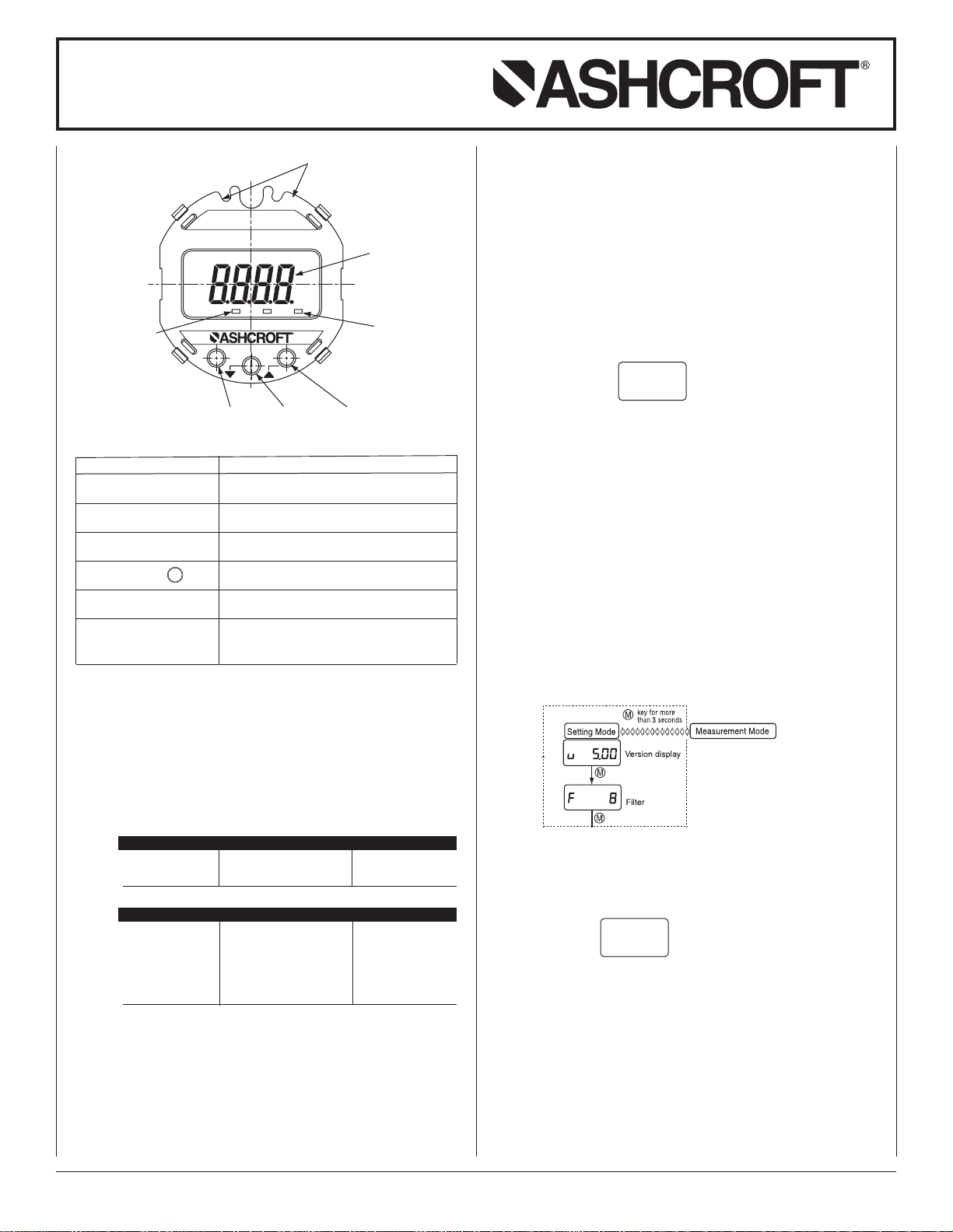
DISPLAY OVERVIEW
Designation
Measured Data Display
Pressure unit monitor
Arbitrary unit monitor
MODE button M
DOWN button #
UP button $
Pressure, linear scaling value, hold value (max./
min), are displayed.
When either indicator is ON, the display is reading in PSI.
When this indicator is ON, the linear scaling value
of an arbitrary unit is indicated on the display.
Used to switch the setting mode, the measurement mode and the setting item.
Used to change (decrease) and select the set
value and to zero-reset the hold function.
Used to change (increase) and select the set
value and to shift from the measurement mode
to the zero adjustment mode.
Function
1. Upon Power-Up the unit enters “Measure Mode” – displaying
applied pressure.
2. Four functions available to the user in “Measure Mode”.
A. Zero Adjustment Mode: Hold the UP$button for more than
3 seconds.This is not to be used for scaling of the output.
• If the zero point adjustment is performed correctly the
message “ADJ” will be displayed for 2 seconds, and
the display will return to the measurement mode.
B. Key Lock
Function Key Manual Indicator
Setting of key lock MODE+
Release of key lock MODE+$one second UnL (Key invalidity)
Operation during keylock
Function Key Manual Indicator
Zero adjust. mode
Hold value reset
Setting mode M key greater than 3 sec LoC (Key invalidity)
Peak indicator
Bottom indicator
$
#
$
#
one second LoC (Key invalidity)
$
key greater than 3 sec LoC (Key invalidity)
key greater than 3 sec LoC (Key invalidity)
one push Peak indicator
one push Bottom indicator
C. Minimum Value “Capture”*: Press DOWN#button to
display the minimum value. The letter “L” will follow the
reading indicating this is the minimum value. Press the
DOWN button again to return to Measurement Mode.
Note: Press the button and release, do not “hold” the but-
ton down (will reset the values).
D. Maximum Value “Capture”*: Press UP$button to dis-
play the maximum value. The letter “H” will follow the
reading indicating this is the maximum value. Press the
UP$button again to return to Measurement Mode.
Note: If the button is held for 3 seconds it will go into
zero adjustment mode.
Minimum/Maximum Reset
The Minimum/Maximum values can be reset when in
either Minimum/ Maximum display by holding the DOWN
button for more than three seconds, “clr” will appear
#
on the display for two seconds and the Minimum and
Maximum values will be removed.
Note: Values are maintained even if unit is powered OFF.
Hold reset
message
clr
• When first using unit be sure to Reset values to clear
values in memory from the factory calibration
process.
• Values are captured starting one minute after Reset,
thus if unit is powered OFF during the one minute the
values during that period will not be kept in memory.
3. Four functions available to the User via “Setting Mode”. To
enter the “Setting Mode” hold “M” key for more than 3 seconds.
(See last page for complete Setting Mode menu.)
A. Filter (Damping)
The filter is based on the moving average of the pressure
data to decrease display “bounce” and to smooth the
analog output due to system pressure fluctuations at the
user’s discretion.
Five selections: 0, 2, 4, 8 and 16 where 0=30ms (and in
this case the filter is not active), 2=60ms, 4=120ms,
8=240ms, 16=480ms, use
keys to change value.
$#
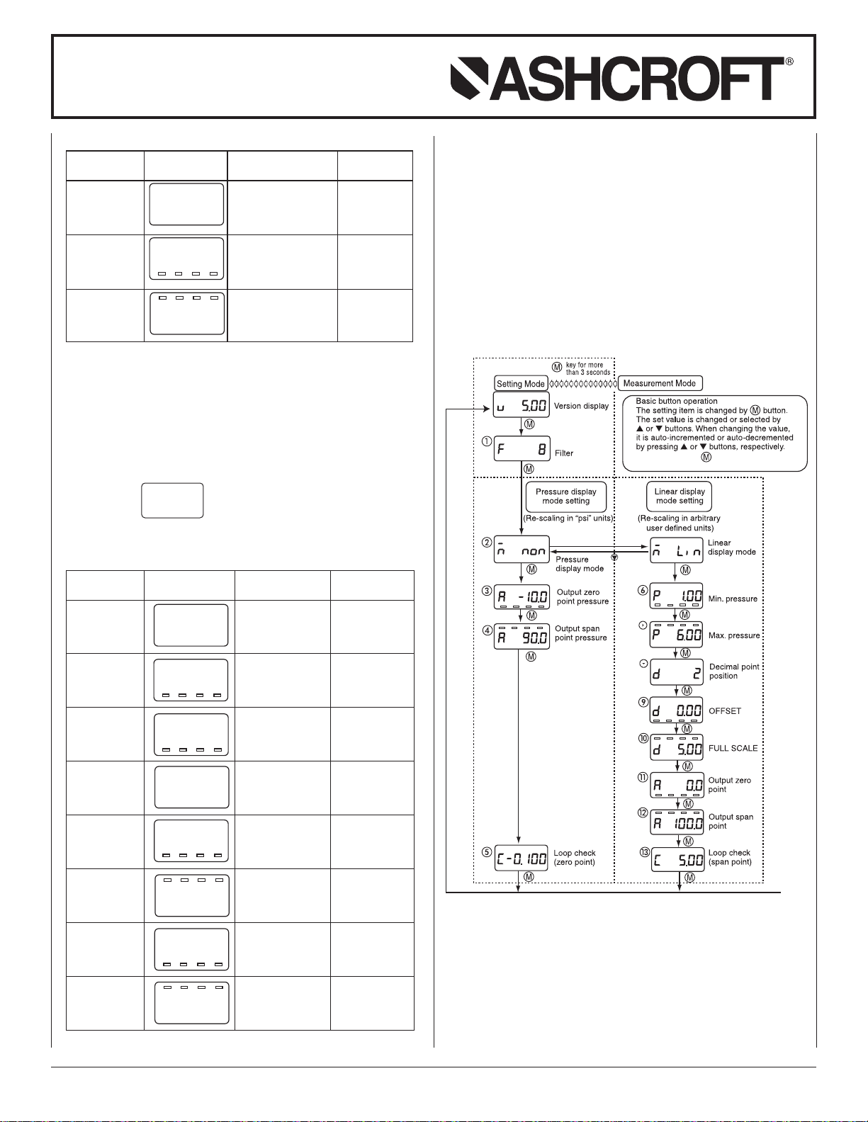
B. Re-scaling in “psi” units: “Pressure Display Mode”
allows for zero (4mA) and span (20ma) adjustment of
–10 to +110% Span respectively.
Note: 1. See menu schematic on last page for detail.
2. Must be in “Pressure Display Mode” option within
“Setting Mode,” this is noted on the screen by
-
n non
Use
keys to move between “Pressure
$#
Display Mode” and “Linear Display Mode” which
is for re-scaling in “Arbitrary” units.
3. To adjust Output Zero Point (4mA) and Output
Span Point (20mA) must be in the functional area
as noted below and then adjustment is via
$#
keys. The value shown is a percentage of the
pressure range (span) as noted on the product
label (ex. If product was supplied as a 0-100psi
range and the user desired the Output Zero Point
to be “moved” from 0 psi to 50 psi then Output
Zero Point would be 50.0 which is 50%.
© 2008 Ashcroft Inc., 250 East Main St., Stratford, CT 06614-5145, USA, Tel: 203-378-8281, Fax: 203-385-0499, www.ashcroft.com
All sales subject to standard terms and conditions of sale. 02/11 I&M011-10163_GC51_Rev. C_Ver. 6.03
Page 2
Quick Start Function Summary Instructions
Note: Holding the button for more than
3 seconds returns to display mode.
for ASHCROFT
(See Complete I&M Manual for Further Detail)
®
GC51 Version 6.03
Notes shown below are from I&M manual.
Setting LCD Setting Setting
Item Display Description Range
Display Selection of non:pressure
mode pressure display display mode
Output Analog Pressure
zero point output zero point range:–10
.
Output Analog Pressure
span point output span point range:–10
Note: For setting of zero point and span point in the analog
output, input the percent value over the pressure range.
C. Re-scaling in “Arbitrary” units: “Linear Display Mode”.
This function allows the user to establish a linear relationship from the standard “psi” unit to any user defined unit.
Note: See menu schematic at end, must be in “Linear
Use
and “Pressure Display Mode.”
-
n non
a 10.0
a 90.0
Display Mode” option within “Setting Mode”, this is
noted on the screen by
-
n L;n
keys to move between “Linear Display Mode”
$#
mode : non Lin: linear
display mode
(4mA) : 10.0 (%Span) to 110% Span
(20mA) : 90.0 (%Span) to 110% Span
D. Loop Check: Use to send a 4-20mA signal meant to
simulate applied pressure, can be accessed either
through Pressure Display Mode or Linear Display Mode.
See “Complete Setting Mode Menu” at end. Loop Check
is noted on the screen with a prefix
is indicating in actual units and starts at the zero
(4mA) point.
If$button continues to be pressed, the linear display
will auto-increment by linkage between the linear display
and the analog output. By continuing to press#button,
auto decrement will occur. Release the button at the
desired indication.
Complete Setting Mode Menu
“
”
. The display
(
Setting LCD Setting Setting
Item Display Description Range
Display Selection of non:pressure
mode pressure display display mode
Minimum Min. pressure Pressure range
pressure corresponding to 0 to 75% Span
Maximum Max. pressure Pressure range
pressure corresponding to 25 to 100% Span
Decimal Display after 0,1,2,3 digit
point decimal point
position Number of digits
OFFSET OFFSET –1999 to 1999
FULL FULL SCALE –1999 to 1999
SCALE corresponding to
Output Analog output Max. display
zero point zero point (4mA) span: –10
Output Analog output Max. display
span point span point (20mA) span: –10
-
n L;n
p 10.0
p 60.0
mode : Lin Lin:Linear display
OFFSET 9
: 10 (psi)
FULL SCALE 10
: 60 (psi)
d 2
d 0.00
d 5.00
a 0.0
a 100.0
corresponding to
min. pressure 6
: 0.00 (ton)
mAX. pressure 7
: 5.00 (ton)
: 0.0 ( %Span) to 110% Span
: 100.0 (%Span) to 110% Span
mode
: 2 (digit)
Notes: Actual values shown are based upon the examples
shown in the I&M Manual.
Changes made within the Setting Mode are saved
by returning to Measurement Mode before powering
the unit “off.”
Note: Values shows are from example in I&M manual.
© 2008 Ashcroft Inc., 250 East Main St., Stratford, CT 06614-5145, USA, Tel: 203-378-8281, Fax: 203-385-0499, www.ashcroft.com
All sales subject to standard terms and conditions of sale. 02/11 I&M011-10163_GC51_Rev. C_Ver. 6.03
Page 3

Quick Start Function Summary Instructions
CASE
DISPLAY
CAP
Inside sensor Line
LCD holder
Notch
Transmission cable
(Twist)
Sheath
+
−
Terminal box
Display (board)
Shield
Power source
+−
Receiver
Transmission cable
Display
Wire terminals
Wire
Turn with a screwdriver
LCD clips (4)
Display board
Power supply
terminal block
1000
750
500
250
0
0 322010
1020
30
Load Limitations 4-20mA Output Only
12 24
545
OPERATING
REGION
Loop Resistance (V)
for ASHCROFT
(See Complete I&M Manual for Further Detail)
4. Wiring
Power supply requirements, 12-36Vdc, note installation
recommendations as follows:
Terminal Strip: SMKDSP1.5/2-5.08 Phoenix contact
A. Cable Requirements
• Two core shielded cable
• Cable outer diameter: 0.35˝ to 0.47˝ (9-12mm)
Required for proper installation with cable gland option
• Wire Gauge: 14-22 AWG (multi-strand or solid)
B. Wiring Instructions
• Do not run pressure transmitter cable / wires within the same
conduit as high voltage (line power) line to reduce the
potential for noise (interference). Use dedicated conduit on
GC51 cables / wires for optimum results.
• Cable diameter, specified above, must be maintained when
using the Cable Gland termination to retain environmental
ratings.
• When connecting shield / drain wire, only connect one end
which should be at the received ground.
• Wire stripping instructions; remove cable jacket 2-3˝ and
strip wires 0.25˝. Shield / drain wire should not be exposed
at the pressure transmitter termination.
®
GC51 Version 6.03
• Remove cover and carefully remove the display to access
the terminal strip, take care not to mishandle the display and
associated electronics.
• Turn display over to expose terminal strip, make positive and
negative connections; insert wire equal to the recommended
strip length (0.25˝).
• After completing connections, align the retaining clips of the
display with the housing’s notches and carefully place into
the housing. Be sure that the internal sensor ribbon cable
does not cross the power supply lines just installed.
• Be sure to properly tighten the sealing grommet when using
the Cable Gland before applying tension to the cable; the
cable gland provides strain relief and environmental sealing.
• Tighten GC51 cover to maintain environmental rating.
• Connect to power source and receiver, than apply power to
confirm correct wiring.
• Power Supply Requirements: Although the 4-20mA signal
can travel over long distances, a very common issue to arise
involves inadequate power at the pressure transmitter – this
results in voltage drop across the loop. Be sure to review the
accompanying table to determine whether the 12-36Vdc has
been received at the pressure transmitter.
LOOP SUPPLY VOLTAGE
min
V
= 12V+[.022A*RL)]
*Includes a 10% safety factor
RL= RS+ R
RL= Loop Resistance (ohms)
R
R
W
S
= Sense Resistance (ohms)
W
= Wire Resistance (ohms)
© 2008 Ashcroft Inc., 250 East Main St., Stratford, CT 06614-5145, USA, Tel: 203-378-8281, Fax: 203-385-0499, www.ashcroft.com
All sales subject to standard terms and conditions of sale. 02/11 I&M011-10163_GC51_Rev. C_Ver. 6.03
LOOP SUPPLY VOLTAGE
Page 4

© 2008 Ashcroft Inc., 250 East Main St., Stratford, CT 06614-5145, USA, Tel: 203-378-8281, Fax: 203-385-0499, www.ashcroft.com
All sales subject to standard terms and conditions of sale. 02/11 I&M011-10163_GC51_Rev. C_Ver. 6.03
 Loading...