

Page 1
Quick Start Function Instructions for
5
Collector/switch 1
LED operation
indicator (OUT 2)
1
4 Digit, 8mm
LED display
4
UP key
3
DOWN key
2
MODE key
6
Setting mode
LED operation
indicator (SET)
5
Collector/switch 1
LED operation indicator
(OUT 1)
2.00˝
3´.00˝
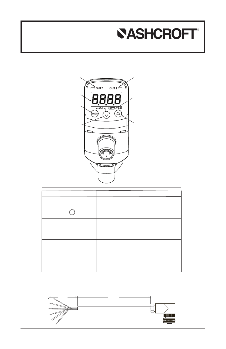
GC35 Heavy Duty Digital Pressure Sensor
Version 1.0 6/06/09
(See Complete I&M Manual for Further Detail)
DISPLAY OVERVIEW
Measurement Display
Mode Key
Down Key #
Up Key $
Collector / Switch LED
Operation Indicator
(OUT1)/(OUT2)
Switch Setting Mode LED
Operation Indicator (SET)
Note: Unit requires M12 mating connector p/n# 611C175-03
© 2010 Ashcroft Inc., 250 East Main St., Stratford, CT 06614-5145, USA, Tel: 203-378-8281, Fax: 203-385-0499,
www.ashcroft.com All sales subject to standard terms and conditions of sale.
8/10 I&M011-10182-GC35 Ver. 6.03 Rev. B
(standard 3 foot length) – see below.
Designation
MODE
Function
Display of pressure, linear scaling
Change to/from switch setting modes and
product’s settings
Change selections / decrease set values
Change selections / increase set values
Indicates switch state. LED indicator will be ON
when switch is activated
Identifies that the switch setting has been
performed
Page 2

1. Measurement Mode is entered when applying power to the unit – LED displays
PRESSURE RANGE (%F.S.)
ANALOG OUPUT (mA dc)
-100 -50 0 50 100 150
20
16
12
8
4
PRESSURE RANGE (%F.S.)
ANALOG OUPUT (mA dc)
-100 -50 0 50 100 150
20
16
12
8
4
applied pressure.
2. Available “Measurement Mode” functions:
A. Zero Adjustment: Press MODE / # keys together ⱖ 3 seconds. This initiates
automatic zero adjustment; ADJ briefly appears on LED display and then returns
to Measurement Mode.
B. Peak / Bottom (Min. Max.) Hold Display: Displayed as $ or # keys are held
for more than 3 seconds and display shows PE+. Values are reset when power
is restored to the unit, or:
Reset Peak: Hold $ key, then press # key
Reset Bottom: Hold # key, then press $ key
C. Key Lock: Prevents overwriting values / tampering – can not be reset by restor-
ing power.
Lock:Press MODE and $ keys together;Lo( appears on LED display for 1 second.
Unlock: Press MODE and $ keys together; UnL appears on LED display for 1
second.
3. Function Setting Mode: Used for product settings, except comparator-switch setting. Accessed by pressing MODE key for more than 3 seconds (complete menu
attached).
A. Comparator Selection: Select ‘Hysteresis’ (kYS) or ‘Window Comparator’ (Yn).
Hysteresis: Switch remains activated until reset point has been achieved.
Window Comparator: Switch activates each time pressure enters a set ‘pressure band’ determined by the A and B settings.
B. Comparator Operation Selection: Select nPn or PnP. Note: LED ring is Blue
with nPn and Green with PnP.
C. Filter Dampening Setting: This is based upon a moving average of pressure
data to reduce display “bounce” and smooth analog output due to system pressure fluctuations. User configurable with five selections:
25ms, 250ms, 2.5s, 5s and 10s.
Filter will not be applied if 0 is selected.
D. Power-Save (Energy-Saving) Setting: Product is equipped with automatic
LED display turn-off feature. User may elect to turn-on display when reading
pressure or using as an indicating instrument.
E. LED Ring Feature Setting: Turns Red when comparator-switch is ON and Blue
(nPn) or Green (PnP) when comparator-switch is OFF.
F. Display Unit Setting: User may alter unit of measures from standard to arbitrary.
G. Display Settings: Allows for decimal point adjustment.
H. Analog Output Scaling: Available with only 1 comparator; function sets analog
output for pressures corresponding to Zero (4mA) and Span (20mA) adjustment
in percentage figures.
Analog output under zero point pressure: After A-L is displayed, select the percentage corresponding with the current analog output value under Zero (4mA)
using
# or $ keys – when pressure range displayed is set to 0.0-100.0% FS.
Analog output under span point pressure: After A-K is displayed, select the percentage corresponding with the current analog output value under Span (20mA)
using
# or $ keys – when pressure range displayed is set to 0.0-100.0% FS.
Example 1) Example 2)
2
Page 3

Comparator Setting Mode
Loop Check Mode
Measurement Mode
Press less
t
han 3 sec.
(In Case of Intact)
(In Case of Intact)
(In Case of Analog Output)
Press 3 sec.
or longer
MODE
MODE
Comparator 1 Use/No Use
MODE
After 1 second
US1
USE
USE
noU
Select with
X W
keys
Message displayed
Current setting
In use Not in use
Setting Storage of Comparator
MODE
After 1 second
Sav
5-I
5-I
5-2
Message displayed
Storage Area Indication
Storage Area 1 Storage Area 2
Comparator 1 Setting Point A
MODE
After 1 second
A-1
5.00
Message displayed
Current setting
X
W
set any desired value within the
–1999 to 9999 range with UP/Down keys
MODE
Comparator 1 ON Delay
After 1 second
on1
0.00
Message displayed
Current setting
X W
set any desired value within the
0 to 2 sec range with UP/Down keys
Comparator 1 Setting Point B
After 1 second
b-1
1.00
Message displayed
Current setting
X W
set any desired value within the
–1999 to 9999 range with UP/Down keys
MODE
MODE
Comparator 1 OFF Delay
After 1 second
oF1
0.00
Message displayed
Current setting
X W
set any desired value within the
0 to 2 sec range with UP/Down keys
Select
X W
keys/reading by long pushing
Select
X W
keys/reading by long pushing
Comparator 2 Use/No Use
M
ODE
After 1 second
US2
USE
USE
noU
Select with
X W
keys
Message displayed
Current setting
In use Not in use
Comparator 2 Setting Point A
MODE
After 1 second
A-2
5.00
Message displayed
Current setting
X W
set any desired value within the
–1999 to 9999 range with UP/Down keys
MODE
Comparator 2 ON Delay
After 1 second
on2
0.00
Message displayed
Current setting
X W
set any desired value within the
0 to 2 sec range with UP/Down keys
Comparator 2 Setting Point B
After 1 second
b-2
1.00
Message displayed
Current setting
X W
set any desired value within the
–1999 to 9999 range with UP/Down keys
MODE
MODE
Comparator 1 OFF Delay
After 1 second
on2
0.00
Message displayed
Current setting
X W
set any desired value within the
0 to 2 sec range with UP/Down keys
MODE
Loop Check Mode
After 1 second
Lop
7.52
Message displayed
Before mode shift
setting value
X W
key to select an arbitrary number
between -10 to 110%F.S.of the current
dispaly unit for simulating the pressure
Setting Loading of Comparator
MODE
After 1 second
Lod
L-1
L-1
l-2
Message displayed
Storage Area Indication
Storage Area 1 Storage Area 2
Function Setting Mode Menu
3
Notes: Values shown are from the example within the complete I&M manual.
Changes made in the Setting Mode are saved by returning to Measurement
Mode before powering off the unit.
Page 4

4. Comparator-Switch / Loop Check Mode: Access by pressing MODE for less
P5I
Function Setting Mode
Filter Setting
Decimal Point Position
Display Unit Setting
Select Comparator Mode
LED Ring Feature Setting
C
omparator Operation
Selection
Measurement Mode
Press 3 sec.
o
r longer
P
ress 3 sec.
or longer
M
ODE
M
ODE
MODE
MODE
MODE
M
ODE
MODE
MODE
MODE
MODE
MODE
MODE
A
fter 1 second
kY5
kY5
!;n
Select with
X W
k
eys
Select with
X W
k
eys
S
elect with
X W
keys
M
essage displayed
Current setting
Hysteresis Window comparator
A
fter 1 second
OP(
npn
npn
pnp
Message displayed
C
urrent unit
setpoint
N
PN output PNP output
S
elect with
X W
keys
EoF
Eon
Power-save OFF Power-saveON
e(O
Message Display Current Setting
e(O
eOf
After 1 second
f;l
f-1
Message displayed
Current setting
After 1 second
lRg
Message Display Current Setting
L
lRI
After 1 second
Select with
X W
keys
ET[
P5I
psi, bar or mPa Display Scaling
UN;
Message Display Current Setting
u
After 1 second
Select with
X W
keys
Power-save setting
(Display Scaling)
Set Offset Value
(Display Scaling Set)
Full Scale Value
Pressure when the
analog is at zero point
Pressure when the
analog is at span point
f-0
Filter off
f-1
Timeconstant25ms
f-2
T
imeconstant 250ms
f-3
Time constant 2.5s
f-4
Time constant 5s
f-5
T
ime constant 10s
Select with
X W
keys
Set Any Desired Position Within the
–100 to 150% range with the
X W
keys
Set Any Desired Position Within the
–100 to 150% range with the
X W
keys
X W
Key to Select Between
(–)1999~(+)9999
X W
Key to Select Between
(–)1999~(+)9999
0
0.0
0.000
0.00
Lr0
No LED interlock
Lr1
Comparator1 is
interlockedwith LED
Lr3
Comparator 1 & 2 are
interlocked with LED
Lr2
Comparator 2 is
interlocked with LED
d-p
Message Display Current Setting
d
0.00
After 1 second
d-l
Message Display Current Setting
d
0.00
After 1 second
d-K
Message Display
Only in Output Selection
Display Scaling
Current Setting
d
0.00
After 1 second
A-L
Message Display Current Setting
a
0.0
After 1 second
a
Message Display Current Setting
a-k
100.0
After 1 second
DI SPL AY S ET TIN G
AN ALO G O UPU T S CAL ING
(n~P
Comparator-Switch Setting / Loop Check Menu
than 3 seconds.
A. Comparator-Switch Setting: To activate / deactivate comparator-switch,
scroll to US1 (4-20mA version only) or US2 and select USE / noU. Enter comparator-switch set point by selecting A-1 or A-2 and use #/$ keys for pressure setting. Now enter ‘deadband’ value (pressure difference between set
and reset values) by selecting b-1 or b-2 and use #/$ keys for setting. Note:
unit automatically configures the reset point. Increasing setpoint is entered as
a positive ‘deadband’ value, while decreasing setpoint is entered as a negative
‘deadband’ value.
B. Loop Check: Allows the user to check comparator-switch operation without
requiring pressure input. Use $ or # keys to view comparator-switch function
in a simulated test of the application.
4
 Loading...