

Page 1
Installation and Maintenance
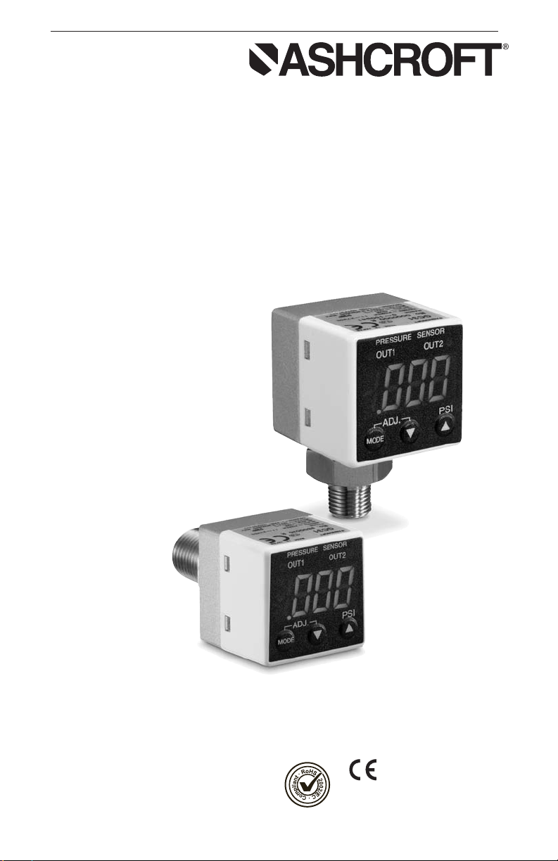
Instructions for GC31
Ultra-Compact Digital
Pressure Sensor
Ashcroft Inc. 250 East Main Street, Stratford, CT 06614 USA
Tel: 203-378-8281, Fax: 203-385-0402 www.ashcroft.com
All sales subject to standard terms and conditions of sale.
© 2009 I&M011-10170 -01/10
LOOK FOR THIS
AGENCY MARK ON
OUR PRODUCTS
1
Version 5.0 10/07
Page 2

2
Page 3

CONTENTS
CAUTION ........................................................................................................................ 4
1. SPECIFICATIONS ............................………………………………………………………. 5
2. DIMENSION DRAWINGS ............................……………………………………………….. 6
3. INSTALLATION............................………………………………………………………….. 6
4. WIRING ..............................………………………………………………………………. 7-8
5. NOISE PREVENTION............................……………………………………………………. 9
6. STORAGE ............................………………………………………………………………. 9
7. MAINTENANCE ............................…………………………………………………………. 9
8. MENU NAVIGATION............................…………………………………………………….. 9-10
9. FUNCTION SETTING MODE ........................……………………………………………….. 10-12
10. SWITCH SETTING MODE ..........................………………………………………………… 12-13
11. SWITCH OPERATION ............................……………………………………………………. 14-15
12. OTHER FUNCTIONS ..........................……………………………………………………… 15
13. ERROR DISPLAY ..........................................……………………………………………. 16
14. MAINTENANCE & WARRANTY ..........................……………………………………………. 17
3
Page 4

4
Page 5

WARNING! READ
BEFORE INSTALLATION
1. GENERAL:
A failure resulting in injury or damage may be caused by excessive overpressure, excessive vibration or pressure pulsation, excessive instrument temperature, corrosion of the
pressure containing parts, or other misuse. Consult Ashcroft Inc., Stratford, Connecticut,
USA before installing if there are any questions or concerns.
2. OVERPRESSURE:
Pressure spikes in excess of the rated overpressure capability of the transducer may cause
irreversible electrical and/or mechanical damage to the pressure measuring and containing
elements.
Fluid hammer and surges can destroy any pressure transducer and must always be avoided. A
pressure snubber should be installed to eliminate the damaging hammer effects. Fluid hammer
occurs when a liquid flow is suddenly stopped, as with quick closing solenoid valves. Surges
occur when flow is suddenly begun, as when a pump is turned on at full power or a valve is
quickly opened.
Liquid surges are particularly damaging to pressure transducers if the pipe is originally empty.
To avoid damaging surges, fluid lines should remain full (if possible), pumps should be brought
up to power slowly, and valves opened slowly.To avoid damage from both fluid hammer and
surges, a surge chamber should be installed.
Symptoms of fluid hammer and surge's damaging effects:
• Pressure transducer exhibits an output at zero pressure (large zero offset).
• Pressure transducer output remains constant regardless of pressure
• In severe cases, there will be no output.
FREEZING:
Prohibit freezing of media in pressure port. Unit should be drained (mount in vertical position
with electrical termination upward) to prevent possible overpressure damage from frozen
media.
3. STATIC ELECTRICAL CHARGES:
Any electrical device may be susceptible to damage when exposed to static electrical charges.
To avoid damage to the transducer observe the following:
• Ground the body of the transducer BEFORE making any electrical connections.
• When disconnecting, remove the ground LAST!
Note: The shield and drain wire in the cable (if supplied) is not connected to the transducer body,
and is not a suitable ground.
4. USE IN LIFE SUPPORT DEVICES
Ashcroft Inc. products are not authorized for use as critical components in life support devices or
systems without the express written approval of the General Manager, Stratford Operations of
Ashcroft Inc.
1. Life support devices or systems are devices or systems which, (a) are intended for surgical
implant into the body, or (b) support or sustain life, and whose failure to perform, when properly
used in accordance with instructions for use provided in the labeling, can be reasonably
expected to result in a significant injury to the user.
2. A critical component is any component of a life support device or system whose failure to perform can be reasonably expected to cause the failure of the life support device or system, or to
affect its safety or effectiveness.
As used herein:
5
Page 6

1. SPECIFICATIONS:
PERFORMANCE SPECIFICATIONS
Analog Output (1–5Vdc):
Accuracy: ±1.0% FS (Accuracy includes the effects of Linearity, Hysteresis and Repeatability)
Response Time: 50msec
Output Resolution: 25mV
Analog Scaling: User may configure analog output scaling to any range within Full Scale
of sensor range
Pressure Switch Output:
Type: NPN or PNP Open Collector up to 30Vdc/80mA
Setting Accuracy: ±1.0% FS
Number of Contacts: 2
Response Time: 5msec-2.0 sec (by user)
Hysteresis: Variable (by user)
Switch Setting: User may adjust switch actuation & deadband to any points within Full
Scale sensor range
Display:
Type: 3½ digit, 10mm LED
Accuracy: ±1.0% FS ± last digit
Display Setting: User may re-configure display scaling, set to capture MIN or MAX value,
and adjust display update rate
Standard Ranges (Gauge):
0 to 50psig, 100psig, 150psig, 300psig, 500psig, 1000psig, 1500psig
Standard Ranges (Compound):
–15 to 15psig, –15 to 75psig, –15 to 150psig, –15 to 300psig
ENVIRONMENTAL SPECIFICATIONS
Temperature Limits:
Storage: –30 to 60ºC (–22 to 140°F)
Operating: –20 to 60ºC (–4 to 140°F)
Compensated: –10 to 50ºC (14 to 122°F)
Temperature Effects:
Zero/Span: ±0.05% FS/°C (from 23°C (–73°F) reference temperature)
Humidity: 0-85% RH (Non-Condensing)
FUNCTIONAL SPECIFICATIONS
Proof Pressure: 2X Range
Burst Pressure: 10X Range
CE Compliance: EN61326-1 2006, EN61326-2-3 2006
ELECTRICAL SPECIFICATIONS
Power Supply Requirements:
Supply Voltage: 11-27Vdc
Current Consumption: 30mA (max)
Switch Contacts: (2) NPN or PNP Open Collector Outputs
NPN Type: 30Vdc/80mA (max)
PNP Type: Sensor Supply Voltage/80mA (max)
MECHANICAL SPECIFICATIONS
Pressure Connection: ¼ NPT Male, G¼B (Opt.)
Enclosure: ABS, Polycarbonate, Aluminum
Rating: IP40
Electrical Connection: 6ft Cable Pigtail
Weight: Approx. 120 grams
Mounting: Panel Mounting Bracket included (Back Connect Only)
Media: Fluids and gases compatible with 304SS (sensor housing) and 17-4 pH SS
(sensor diaphragm)
6
Page 7

2. PRODUCT DIMENSIONS
Lower Connect Type with1⁄4NPT Male (G1⁄4B optional)
1.18
30
1.18
30
1.18
30
1.57
Back Connect Type with
1
⁄4NPT Male (G1⁄4B optional)
.79
20
.79
20
1.57
40
.35
9
1.26
32
40
PRESSURE SENSOR
OUT1
PSI
MODE
ADJ.
OUT2
PRESSURE SENSOR
OUT1
PSI
MODE
ADJ.
OUT2
Product label
PROCESS CONNECTIONS
1
⁄4NPT Male Standard
G
1
⁄
4B (PF) Optional
HEX .67
.28
.63
.12
Ø.20
G1/4B (PF)
.63
.28
[7]
HEX .67
1/4NPT
[7]
[5]
[5]
[17]
[16]
[17]
[16]
7
Page 8

3. INSTALLATION
GC31
(Brown)
(Black-White)
(Orange)
(Blue)
Load 10k V min.
Power (+)
Power (–)
1-5Vdc
1.42
– .0000
+ .0236
36
0
+ 0.60
1.42
– .0000
+ .0236
36
0
+ 0.60
Panel cutout
dimension
Front of Panel
Panel
Adapter #1
Panel
Adapter #2
Back of Panel
Panel Cutout
Main Body
Install in a location where vibration and shock can be minimized and without direct sunlight on
the display in compliance with IP40 environmental rating.
(Pressure port connection:1⁄4NPT male 11⁄2 turns hand tighten.)
Note: Panel mount adapter for back connection only. Do not attach panel mount adapters
prior to panel installation or out of sequence as stated below.
1.) Take Panel Adapter #1 (tube notch faced down) and mount to the main body with panel placed
in between as pictured. Push adapter and main body together until tabs engage notches.
2.) Take Panel Adapter #2 (tube notch faced down) and attach to the back of the main body. Push
until panel adapter tabs engage the main body notches.
3.) Gently push panel adapters together until gaps are minimized.
4. WIRING
Cable wire colors are shown below. Power on after checking connections. when on wait at
least 5 minutes before performing a zero point adjustment or measurement to ensure system
is stabilized.
Brown…………………………….. Power (+)
Blue………………………………. Power (–)/COM
Orange……………………………. Analog output (+)
Black……………………………… Open collector output OUT 1 (+)
White……………………………… Open collector output OUT 2 (+)
Analog Output (1-5VDC)
8
Page 9

NPN Type Switch Function (wiring to relay)
GC31
(Brown)
(Black-White)
80mA max.
(Blue)
Power (+)
Power (–)
Relay Output
Relay
Protective transistor diode
(ensure to install)
Note: Ensure that the relay’s operation coil rated current
and voltage are within the transistor’s rating.
GC31
(Brown)
(Black-White)
80mA max.
(Blue)
Power (+)
Power (–)
Relay Output
Relay
Protective transistor diode
(ensure to install)
Note: Ensure that the relay’s operation coil rated current
and voltage are within the transistor’s rating.
GC31
(Brown)
(Black-White)
80mA max.
(Blue)
Power (+)
Power (–)
Photo coupler
Open collector output
Electric current resistance
GC31
(Brown)
(Black-White)
80mA max.
(Blue)
Power (+)
Power (–)
Voltage HL output
(High/Low)
Pullup resistance
NPN Type Switch Function (wiring to photocoupler)
NPN Type Switch Function (voltage output)
PNP Type Switch Function (wiring to relay)
9
Page 10

GC31
(Brown)
(Black-White)
80mA max.
(Blue)
Power (+)
Power (–)
Photo coupler
Open collector output
Electric current resistance
GC31
(Brown)
(Black-White)
80mA max.
(Blue)
Power (+)
Power (–)
Voltage HL output
(High/Low)
Pulldown resistance
PRESSURE SENSOR
OUT1
PSI
MODE
ADJ.
OUT2
Comparator/Switch Output Status LED
(OUT 1)
(OUT 2)
MODE
MODE KEY
DOWN KEY
UP KEY
PNP Type Switch Function (wiring to photocoupler)
PNP Type Switch Function (voltage output)
5. NOISE PREVENTION
Power Supply
The pressure display can fluctuate and provide incorrect output if noise is present in the
power supply/wire. Care should be taken to keep the GC31 power supply wires from high
voltage lines and use a power line with a high noise rejection ratio.
6. STORAGE
Store in a location in compliance with the environmental rating of the unit and within -30 to
+60C (-22 to 140F). Avoid direct exposure of the display to Sunlight.
7. MAINTENANCE
Although this is a solid state device, it is recommended that a visual inspection be conducted
twice a year along with regular zero adjustment if necessary.
8. MENU NAVIGATION
Functions
PLEASE NOTE: Do not use sharp objects to press the keys as this can puncture the panel.
See illustration for External Panel and Functions.
10
Page 11

Pressing the MODE key for 3 seconds displays “---”. To return to measurement mode from
each setting mode, the “---” display will flash when 3 seconds have passed.
Comparator setting mode
Loop check mode
• Hysteresis operation setting
Setting point, deadband setting
On, Off delay time setting
• Window comparator operation setting
Output setting range setting
On, Off delay time setting
• Loop check mode
Manually test display value, comparator output and analog output without
relation to applied pressure
MODE
More than 3 sec
Measurement mode
Power
• Pressure display
• Comparator output
• Analog output
䉱
or
Peak
(While
pressing)
Peak hold display mode
• Peak hold display
Max. display value display
• Bottom hold display
Min. display value display
Less than 3 sec
MODE
䉲
Bottom
MODE
More than 3 sec
MODE
Less than 3 sec
+
MODE
More than 3 sec
Finish
䉲
Function setting mode
• Comparator operation selection
• Display selection
• Display value scaling selection
• Filter selection
• Analog output scaling selection
Zero point adjustment mode
• Zero point adjustment of
display value
9. FUNCTION SETTING MODE
Setup Steps
Pressing the MODE key for 3 seconds displays “___” to return to measurement mode from
each setting mode, the “___” display will flash when 3 seconds has passed. The setting mode
is used to select switch operation, pressure unit indication scaling, scaling of analog output
and filter time constant.
11
Page 12

Function Setting Mode
Measurement Mode
Press > 3 sec.
Press > 3 sec.
MODE
MODE
(Comparator
operation selection)
MODE
(Display selection)
MODE
(In SI unit
selection)
(Only in display function selection)
(Scaling of LED display)
Decimal point position
MODE
(Scaling of LED display) Indicated
value at min. pressure range
MODE
(Scaling of LED display) Indicated
value at max. pressure range
MODE
(Filter selection)
MODE
(Only in output option selection)
(Analog output scaling) Pressure when
the analog output is at zero point
MODE
(Analog output scaling) Pressure when
the analog output is at span point
MODE
After 1 second
(nP
kY5
kY5
!;n
Select with
X W
keys
Select with
X W
keys
Message displayed
Current setting Hysteresis
Hys or
Window comparator
Win
After 1 second
un;
npa
+pa
npa psi
ETC
Message displayed
Current unit
setpoint
Pressure indication by a SI unit
kPa
MPa or
et(
Indication scaling displayed
etc.
After 1 second
d-P
.003
Message displayed
3 2 1 0
After 1 second
d-l
.000
Message displayed
Set any desired position within the
0 to 3 range with the
X W
keys
1.8.8.8
After 1 second
d-k
1.000
Message displayed
After 1 second
f;l
f-1
Message displayed
Current setting
Set any desired position within the
–1999 to 1999 range with the
X W
keys
Set any desired position within the
–1999 to 1999 range with the
X W
keys
Select with
X W
keys
f-0
Filter off
f-1
Time constant 25ms
f-2
Time constant 250ms
f-3
Time constant 2.5s
f-4
Time constant 5s
f-5
Time constant 10s
A-l
Set any desired position within the
–100 to 150% range with the
X W
keys
Message displayed
After 1 second
a-k
Set any desired position within the
–100 to 150% range with the
X W
keys
Message displayed
After 1 second
100.0
0.0
psi
Caution: Editing the setting value in function setting mode resets all of the setting values
including the switch. Please note that when the reset setting values are out of the display
range, they will be adjusted to an upper or lower limit value that can be processed internally.
9A. SWITCH OPERATION
Select “Switch Operation Selection” with the MODE key. The message (np is displayed
for 1 sec. and then the current setting is displayed. Select either hysteresis or switch operation display with the keys.
9B. DISPLAY SELECTION
Select “Display Selection with the MODE key. The message displayed for 1 sec. and then
the current setting is displayed. Select pressure display by PSI or display scaling (Arbitrary
unit defined by user) with the keys.
12
Page 13

9C. SELECTING STANDARD OR CUSTOM SCALING MODE
When the et( is selected in “Display Selection”, the display value of pressure for applied
pressure displays as an arbitrary scaling display. This is a function to scale the MIN/MAX display value and has NO effect on applied pressure and analog output.
9D. CUSTOM SCALING MODE
Use the MODE key to set “Decimal point position”, “Minimum pressure range display value”
and “Maximum pressure range display value” of “Display scaling”.
Example:With a pressure range of 0 to 150 psi (0 to 100% FS), main unit display of 000.0 to
150.0 (factory set) is changed to a display of 0.000 to 1.000. (User defined unit, in this case 1MPa)
d-p Dec. point position (from least significant digit): 0.1 .003
d-l Min. pressure range value: 0.0 .000
d-k Max. pressure range value: 150.0 1.000
9E. FILTER SECTION
The GC31 is equipped with 5 internal time constant filters. Use this function when pressure
fluctuations can result in erratic, difficult to read displays. The time constant for the selected
filters reflects on the switch outputs as well as the analog output.
Select “Filter Selection” with the MODE key. The message f;l is displayed for 1 sec. and
then the current setting mode’s decimal point position is displayed. Change the decimal point
position value with the keys.
Entering the setting value in function setting mode resets all of the setting
f-0 No filter
f-1 Time constant 25ms
f-2 Time constant 250ms
f-3 Time constant 2.5 sec
f-4 Time constant 5 sec
f-5 Time constant 10 sec
9F. ANALOG OUTPUT SCALING
This mode is for setting the pressure for the analog output zero point and span point. Display
by analog selection is scaled as 0 to 100% (Zero point: 1Vdc, span: 5Vdc). Select “Analog
Scaling” with the MODE key.
The message a-l is displayed for 1 sec. and the current pressure’s analog output zero
point (1Vdc) is displayed as a percentage. Change the numeric value with the keys.
The message a-k is displayed for 1 sec. and the analog output span point’s pressure can
be set in the same way using the keys.
Example: With Analog output of 1 to 5Vdc at pressure range of 0 to 100 psi (0 to 100% FS),
output is changed to 1 to 5Vdc at 0 to 90 psi.
Set the analog output zero point: 0.0% FS 0.0% FS (1Vdc output with pressure range 0% FS).
Set the analog output span point: 100.0% FS 90% (5Vdc output with pressure range 90% FS).
10. SWITCH SETTINGS MODE
Setup Steps
In Measurement Mode press the key (release within 3 sec.) to change to Switch Setting Mode.
Switch Setting Mode
There are two switches, OUT1 and OUT2. Both “Hysteresis (upper/lower limit)” and “Window
Comparator” operations can be selected in the function setting mode (switch operation selection). Those two operations can be selected at once, and can be set. Both OUT1 and OUT2
can be set independently to a max on/off delay of 2 seconds. In the following explanation, if
the switch’s output conditions are met their output state will become On, and “Switch LED
(OUT1, OUT2)” will light up.
13
Page 14

NOTE: if the switch’s setting value is set outside the display range, the switch’s setting value
Comparator Setting Mode
Loop Check Mode
Measurement Mode
Press < 3 sec.
Press > 3 sec.
MODE
MODE
(Output1. Comparator
setting point A)
MODE
After 1 second
a-1
50.0
XW
Message displayed
Set any desired value within
the –1999 to 1999 range with
Up/Down keys
(Output1. Comparator
setting point b)
MODE
After 1 second
b-1
10.0
XW
Message displayed
Set any desired value within
the –1999 to 1999 range with
Up/Down keys
(Output1. Comparator
on delay time)
MODE
After 1 second
on1
0.00
XW
Message displayed
Set any desired value within
the 0 to 2 second range with
Up/Down keys
(Output1. Comparator
off delay time)
MODE
After 1 second
of1
2.00
XW
Message displayed
Set any desired value within
the 0 to 2 second range with
Up/Down keys
(Output2. Comparator
setting point A)
MODE
After 1 second
a-2
50.0
XW
Message displayed
Set any desired value within
the –1999 to 1999 range with
Up/Down keys
(Output2. Comparator
setting point b)
MODE
After 1 second
-10.0
XW
Message displayed
Set any desired value within
the –1999 to 1999 range with
Up/Down keys
(Output2. Comparator
on delay time)
MODE
After 1 second
on2
0.10
XW
Message displayed
Set any desired value within
the 0 to 2 second range with
Up/Down keys
(Output2. Comparator
off delay time)
MODE
After 1 second
of2
1.00
XW
Message displayed
Set any desired value within
the 0 to 2 second range with
Up/Down keys
(Loop check mode)
After 1 second
lop
0.0
XW
Message displayed
Set any desired value within
the –1999 to 1999 range with
Up/Down keys
MODE
b-2
can be rewritten automatically by the function setting mode operation.
14
Page 15

11. SWITCH OPERATION – HYSTERESIS/DEADBAND
Setting the upper limit
This is the mode in which the switch operates with the setting value (A) as the upper limit.
The upper limit setting is determined when you select a positive number (including 0) for setting value (b).
Setting the lower limit . . . . . . . .
This is the mode in which the switch operates with the setting value (A) as the lower limit. The
lower limit setting is determined when you select a negative number for setting value (b).
15
Page 16

Loop check function
At the end of the Switch Operation Menu is the Loop Check function. Using the MODE key
to select the Loop Check function. After lop is displayed for 1 second, the value of the latest measurement mode is displayed as default. Use keys to set displayed value anywhere between –1999 and 1999 to confirm switch operations and/or analog output operation.
12. OTHER FUNCTIONS
Basic Key Operations
In all setting modes, values are set with the keys. Use the key to increase and
the key to decrease the value. A repeat state occurs in three phases of speed when the
keys are pressed for more than 0.5 seconds to increase or decrease numerical value.
keys are also used for setting switch, unit and filter in the function setting mode.
Re-Zero of Sensor
In measurement mode, select display to adjust zero using key. Press MODE + keys for
more than 3 second (until “---” display blinks) after releasing pressure from the pressure port.
Automatic zero adjustment takes place approximately 1 second later for pressure display to
be zero.
When the zero adjustment is successful, Adj is displayed.
Error displays e-0 for 1 second when applied pressure was outside of range of –5 to 5%
FS, zero adjustment will not be allowed.
16
Page 17

Maximum/Minimum Pressure Capture
The GC31 unit keeps the maximum and minimum pressure level applied to the pressure port
as peak and bottom values respectively, in the internal memory. The peak and bottom values
are displayed while holding the or keys respectively. Message pe+ is displayed for one
second and selected Max/Min value is displayed by this operation. Maximum and minimum
values are reset when you reset power to the unit or by the following procedure:
Resetting Maximum value: While holding the key, press the key.
Resetting Minimum value: While holding the key, press the key.
13. ERROR DISPLAY
An error message and pressure value are alternately displayed when one of the following
errors occurs in the measurement mode (in case of “Out of pressure display range” error, only
error message is displayed). Check the content of error message and taken the action below
immediately.
Error
display Contents Actions
Out of pressure display range (Upper limit)
Pressure above 110% FS of pressure had been
fff
applied, or the indicated value exceeded 1999. Adjust the applied pressure
Out of pressure display range (Lower limit)
-fff
Pressure below –10% FS had been applied, or
the indicated value fell below –1999.
Pressure applied during the zero point Open the unit to atmosphere
e-0 adjustment,was outside the range by and perform zero point
± 10% FS. adjusment.
e-1 Comparator 1 overloaded
e-2 Comparator 2 overloaded
e12 Comparator 1 & 2 overloaded
within the rated pressure.
Drop load current below
80mA before use.
Turn power on again to
recover from error status.
17
Page 18

14. MAINTENANCE AND WARRANTY
Periodic Inspection
Depending upon the type of use periodic inspection is recommended at least once a year.
Please refer to the following items for periodic inspection.
1. Appearance
2. Display/output check via appropriate pressure standard
3. Display/output check via Loop Check
(2)
(1)
CAUTION
• Avoid electrostatic charging. When cleaning this product, please use a soft, damp cloth.
• Do not use thinner, etc. which may cause deterioration and failure.
Product warranty
Except as otherwise provided, the product warranty of this product is as follows:
Period: 12 months after delivery
Warrantable defects: Defects resulting from the design and manufacture of our company,
the quality of the material, etc.
Implementation of warranty: This warranty will be completed by substitution or repair of
the product concerned.
Consequential damages caused by product defects are not the reponsibility of the
manufacturer.
• If you have any questions about this document, please contact the sales office or distributor
nearest you.
• This document is subject to change without notice due to upgrade, etc.
(1) If zero correction is required refer to section 13.
(2) Loop check, see section 12.
18
Page 19

19
Page 20

© 2009 Ashcroft Inc. 250 East Main Street, Stratford, CT 06614 USA
Tel:203-378-8281, Fax: 203-385-0402 www.ashcroft.com
All sales subject to standard terms and conditions of sale.
I&M011-10170 -01/10
20
 Loading...