

Page 1
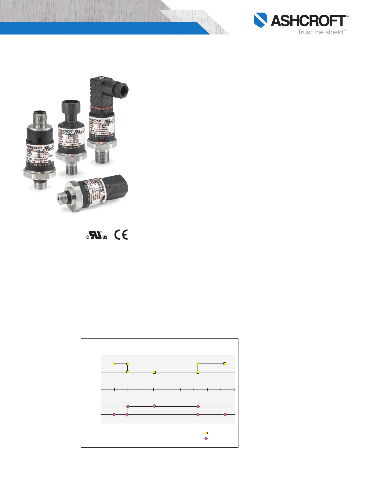
Model G2 Pressure Transducer
TOTAL ERROR BAND (TEB)
Error limits of all points (0-100% of range)
Error (% of span)
Ambient Temperature (C)
-60 -40 -20 0 20 40 60 80 100 120 140
2.0%
1.5%
1.0%
0.5%
0.0%
-0.5%
-1.0%
-1.5%
-2.0%
Pos Error Limit
Neg Error Limit
DIN43650
onnection
C
Metri-Pack
M12
onnection
C
BULLETIN G2
Connection
LOOK FOR THESE AGENCY
MARKS ON OUR PRODUCTS
Deutsch
onnection
C
APPLICATONS
The G2 pressure transducer combines
performance with value to meet the
demanding needs of the original equipment manufacturer in applications
ound in:
f
• Off-road Equipment
• Construction Machinery
• Performance Racing
• Railroad/Transportation
• Compressor Control
• HVAC and Refrigeration
• Agricultural Implements
• Process Automation and Control
• Hydraulic & Pneumatic Sensing
• Pump Monitoring
FEATURES
• 1% Total Error Band Accuracy
• Broad Temperature Capability
• All-welded pressure construction
• High EMI/RFI rating
• Ranges 30 psi through 20,000 psi
• IP 67 Ingress rating
• Diagnostic rails
The Ashcroft®Type G2†pressure transducer
has been specifically designed with the high
volume OEM in mind.
A ±1% Total Error Band accuracy is accomplished by marrying a high performance ASIC
to a very stable, field proven polysilicon thin
film pressure sensor. The sensor is electron
beam welded to a pressure fitting of stainless
steel, which provides excellent overpressure
capability and outstanding durability in the
presence of shock and vibration.
The circuitry is held within an internal cage
and housed in an enclosure of reinforced Nylon.
All specifica tions are subject to change witho ut notice.
All sales subject to standard terms a nd conditions.
© 2016 Ashcrof t Inc. Re v. 06/16
ERFORMANCE SPECIFICATIONS
P
Ref. Condition 21°C ±1°C (72°F ±2°F)
Accuracy:
Total Error Band includes combined effects of temperature, non-linearity (Terminal Point Method), hysteresis,
non repeatabilty, zero offset and span setting errors
±1% of Span: From –20 to 85ºC (–4 to 185ºF)
±1.5% of Span: From –40 to –20ºC (–40 to –4ºF)
±1.5% of Span: From 85 to 125ºC (185 to 257ºF)
Note: Static accuracy ±0.25% of span BFSL (Best Fit
Straight Line Method); includes non-linearity,
hysteresis and non-repeatable effects at reference
temperature 72°F (21°C)
Stability: Less than ±0.25% span/year
Durability: Tested to 50 million cycles
ENVIRONMENTAL SPECIFICATIONS
Temperature:
Compensated –40 to 125°C (–40 to 257°F)
Operating –40 to 125°C (–40 to 257°F)
Storage –40 to 125°C (–40 to 257°F)
Humidity: 0 to 100% R.H., no effect
FUNCTIONAL SPECIFICATIONS
Select from over 25 pressure ranges starting at 30
psi and running through 20,000 psi gauge.
Compound (vacuum & pressure) ranges are also
available, see “To Order” on back.
Overpressure (F.S.): Proof Burst
750 psi & below 200% F.S. 1000% F.S.
1500 psi 200% F.S. 500% F.S.
3000 psi 200% F.S. 500% F.S.
5000 psi 150% F.S. 500% F.S.
7500 psi 120% F.S. 500% F.S.
10,000 psi 120% F.S. 240% F.S.
20,000 psi 120% F.S. 240% F.S.
Vibration: Random vibration (20 g) over temperature range (–40° to 125°C). Exceeds typical MIL.
STD. requirements
Shock: 100gs, 6 ms
Drop Test: Withstands 1 meter on concrete 3 axis
Response Time: Less than 1 msec
Warm-up Time: Less than 500 msec typical
Position Effect: Less than ±0.01% span, typical
ELECTRICAL SPECIFICATIONS
Output Signals Available:
Supply
Voltage Output Excitation Current
0-5 Vdc, 3 wire 9-36 Vdc 5mA
0-10 Vdc, 3 wire 14-36 Vdc 5mA
1-5 Vdc, 3 wire 9-36 Vdc 4mA
1-6 Vdc, 3 wire 9-36 Vdc 4mA
0.5-4.5Vdc, 3 wire 9-36Vdc 4mA
Ratiometric Output:
0.5-4.5 Vdc, 3 wire 5 Vdc ±0.5 Vdc 3.5mA
Current Output:
4-20mA, 2 wire 9-36 Vdc
Reverse Polarity & Miswired Protected: Yes
Insulation Breakdown Voltage: 100 Vac
Insulation Resistance: Greater than 100 megohms
at 100 Vdc
CE Marked: Per DoC
EMC Directive 2004/108/EC
IEC/EN 61326-1:Edition 1.0 Industrial
IEC/EN 61326-2-3:Edition 1.0 Annex BB Industrial
PED Directive
Ashcroft Inc., 250 East Main S treet, Str atford, CT 06614 USA
Tel: 203-385-0648 • Fax: 20 3-385-0408
email: info@ash croft.com • www.ashcroft.com
Page 2
10
40
9 (min)
36 (max)
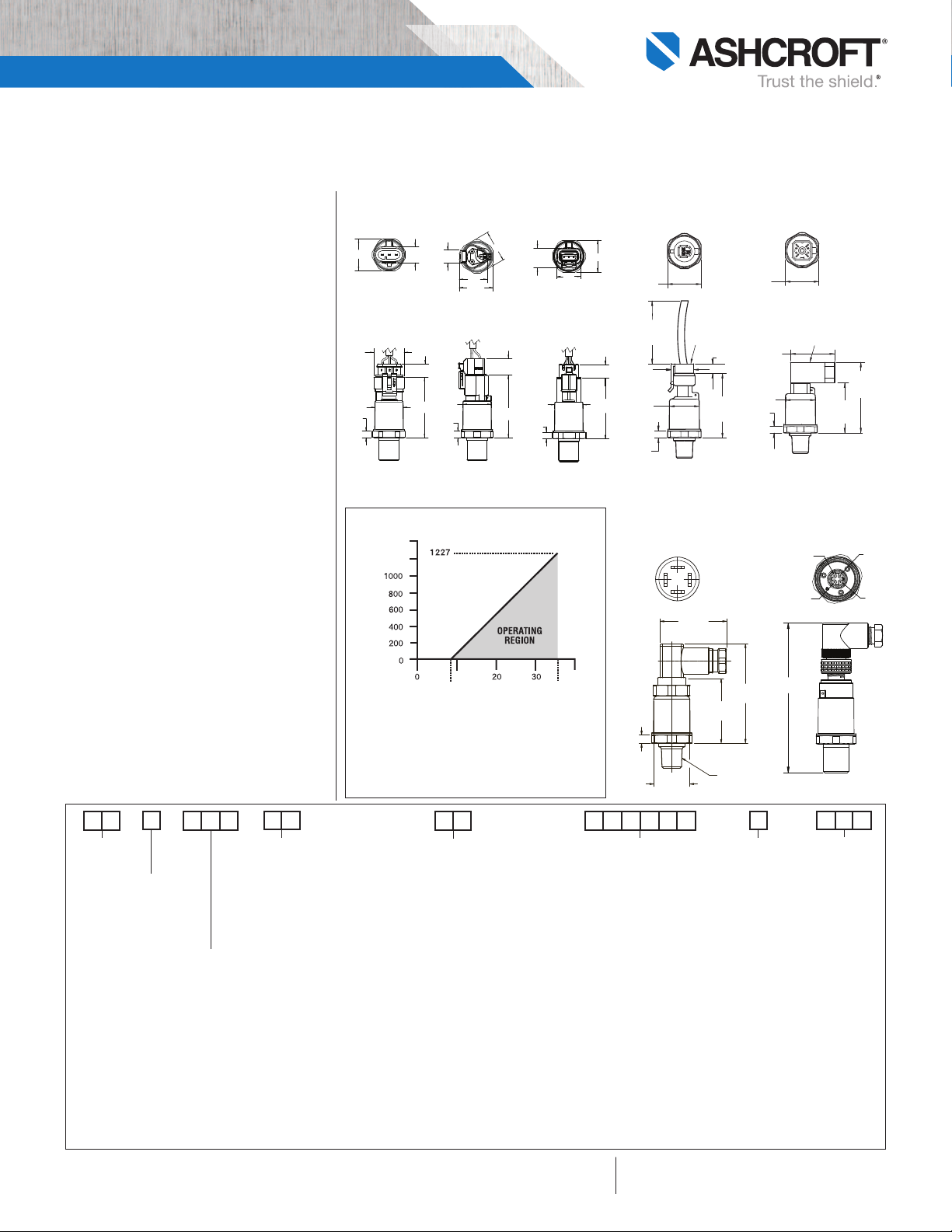
Loop Supply Voltage (Vdc)
[LSV]
Power Supply Voltage vs. Loop Resistance
(4-20mA ONLY)
Loop Resistance (R
L
-Ohms)
1400
1200
Model G2 Pressure Transducer
1.40
1.59
.23
.94
1.06
(27)
1.06
(27)
(36)
MINI HIRSCHMANN**
(24)
.94
(24)
.71
(18)
2.24
(57)
(6)
2.05
(52)
.30 (8)
.23
(6)
(40)
Wire
Length
3-PIN METRI-PACK*
AMP SUPERSEAL
DEUTSCH DT04-3P
DEUTSCH DTM04-3P
.23
Ø
.94
2.03
.45
1.02
1.06
.54
2.11
.56
.23
.94
.95
1.13
1.06
.44
.23
2.04
.46
Ø
.94
1.06
.81
.67
Optional
Mating
Connector
Optional
Mating
Connector
Mates to Metri-Pack
Connector Body 12065286
Mates to Hirschmann G4W1F
Connector or Similar
Ø0.95
[Ø24.0]
1.69
[42.9]
1.74
[44.2]
2.60
[65.9]
0.23
[5.7]
1/4 NPT
Connection - PINC
1
2
3
V out
V
s
-
V
s
+
3.992 TYP
Install height
P
in 1
P
in 2
P
in 3
P
in 4
UL Recognized component per UL-61010-1, CSA
22.2 6101-1 Electrical Equipment for Measurement,
Control and Laboratory use.
PHYSICAL SPECIFICATIONS
Wetted Materials: 304SS pressure connection and
17-4PH SS sensor diaphragm
Housing: 20% Glass Reinforced Nylon,
Fire retardant to UL94 V1
Available Process Connections (Male):
See “How To Order” section below. For other
connections consult factory.
Ingress Rating:
• IP67, NEMA 4X:
- Metri-Pack I50 series*
- Shielded cable
- Flying leads
- Deutsch DT Series DT04-3P
- Deutsch DTM Series DTM04-3P
- AMP Superseal
- M12 - Mates to Hirschmann 933 172-100 or similar
• IP65, NEMA 4X:
- Hirschmann G series**
- EN 175301-803, Form C (DIN 43650, Form C)
ELECTRICAL TERMINATION
See “How To Order” section below for electrical
termination options.
DIMENSIONS
EN 175301-803, Form C
(DIN 43650, Form C)
M12 4-POLE PLUG
How To Order
Type
Configuration
(G2)
Accuracy
1.0% Total Error Band
–20°C/+85°C
1.5% Total Error Band
–40°C/-20°C, 85/125°C
BULLETIN G2
G 2
Output Signal
05 = 0-5 Vdc
10 = 0-10 Vdc
15 = 1-5 Vdc
16 = 1-6 Vdc
42 = 4-20mA
45 = 0.5-4.5Vdc
9-36Vdc supply
RM= 0.5-4.5 Vdc
Pressure Connection
M011⁄8 NPT-male
1
M02
⁄4 NPT-male
7
MEK
⁄16-20 SAE-male
w/Buna-N O-ring
M38 3⁄8-24 SAE-male
w/Buna-N O-ring
9
MEV
⁄16-18 SAE-male
w/Buna-N O-ring
M333⁄8-24 UNJF3A (w/37° cone seat)
7
M76
⁄16-20 UNJF-3A (w/37° cone seat)
1
MS2
⁄4-19 bsp male
MG2 G 1⁄4 B male
Consult factory for other connections
† Not UL recognized above 10,000 psi range.
†
†
†
Metri-Pack*
GN = no mating conn.
G2 = mating conn. 3´cable
G3 = mating conn. 10´cable
G1 = mating conn. w/customer
Hirschmann G Series**
Ratio Metric to
5Vdc supply
HM = no mating conn.
M1 = with mating conn. no cable
M2 = mating conn. 3´cable
P9 = mating conn. w/customer
Flying Leads
W2 = 3´flying leads
W9 = customer specified length
Shielded Cable
F2 = 3´shielded cable
F3 = 10´shielded cable
P1 = customer specified length
M12 – Mates to Hirschmann
EW = w/o mating conn.
E0 = w/mating conn. no cable
E2 = w/mating conn. &
E1 = w/mating conn. &
**Metri-Pack is a trademark of Delphi Packard Electric Systems.
**Trademark of Richard Hirschmann of America, Inc.
VdcMIN = 9V + [0.022A X (RL]
RL= RS+ R
RL= Loop Resistance (ohms)
R
RW= Wiring Resistance (ohms)
W
= Sense Resistance (ohms)
S
Electrical Termination
specified length
specified length
933 172-100 or similar
3´shielded cable
customer defined length
All specifica tions are subject to change witho ut notice.
All sales subject to standard terms a nd conditions.
© 2016 Ashcrof t Inc. Re v. 06/16
Deutsch DT Series DT04-3P
DT = w/out mating conn.
T2 = w/1m, 3´cable
T3 = w/3m, 10´cable
T1 = w/mating conn. cable
customer defined length
Deutsch DTM Series DTM04-3P
DS = w/out mating conn.
S2 = w/1m, 3´cable
S3 = w/3m, 10´cable
S1 = w/mating conn. cable
customer defined length
AMP Superseal
AP = w/out mating conn.
A2 = w/1m, 3´cable
A3 = w/3m, 10´cable
A1 = w/mating conn. cable
customer defined length
EN 175301-803, Form C
(DIN 43650, Form C)
DC = no mating conn.
N1 = with mating conn. no cable
N2 = mating conn. 3´cable
N3 = mating conn. 10´cable
N9 = mating conn. w/customer
specified length
X 7
Pressure Ranges
psi Ranges
30# = 30 psi
50# = 50 psi
60# = 60 psi
100# = 100 psi
150# = 150 psi
200# = 200 psi
300# = 300 psi
400# = 400 psi
500# = 500 psi
750# = 750 psi
1000# = 1000 psi
1500# = 1500 psi
2000# = 2000 psi
3000# = 3000 psi
4000# = 4000 psi
5000# = 5000 psi
6000# = 6000 psi
7500# = 7500 psi
10000# = 10000 psi
15000# = 15000 psi
20000# = 20000 psi
Measurement Type
G = Gauge Pressure
Compound Ranges
30#&vac = 30 psi/-14.7 psi
45#&vac = 45 psi/-14.7 psi
60#&vac = 60 psi/-14.7 psi
85#&vac = 85 psi/-14.7 psi
100#&vac = 100 psi/-14.7 psi
150#&vac = 150 psi/-14.7 psi
200#&vac = 200 psi/-14.7 psi
300#&vac = 300 psi/-14.7 psi
-
Ashcroft Inc., 250 East Main S treet, Str atford, CT 06614 USA
Tel: 203-385-0648 • Fax: 20 3-385-0408
email: info@ash croft.com • www.ashcroft.com
Optional
X-Variations
Consult Factory for
Available Options
 Loading...