

Page 1
Installation and Maintenance
Instruction Manual
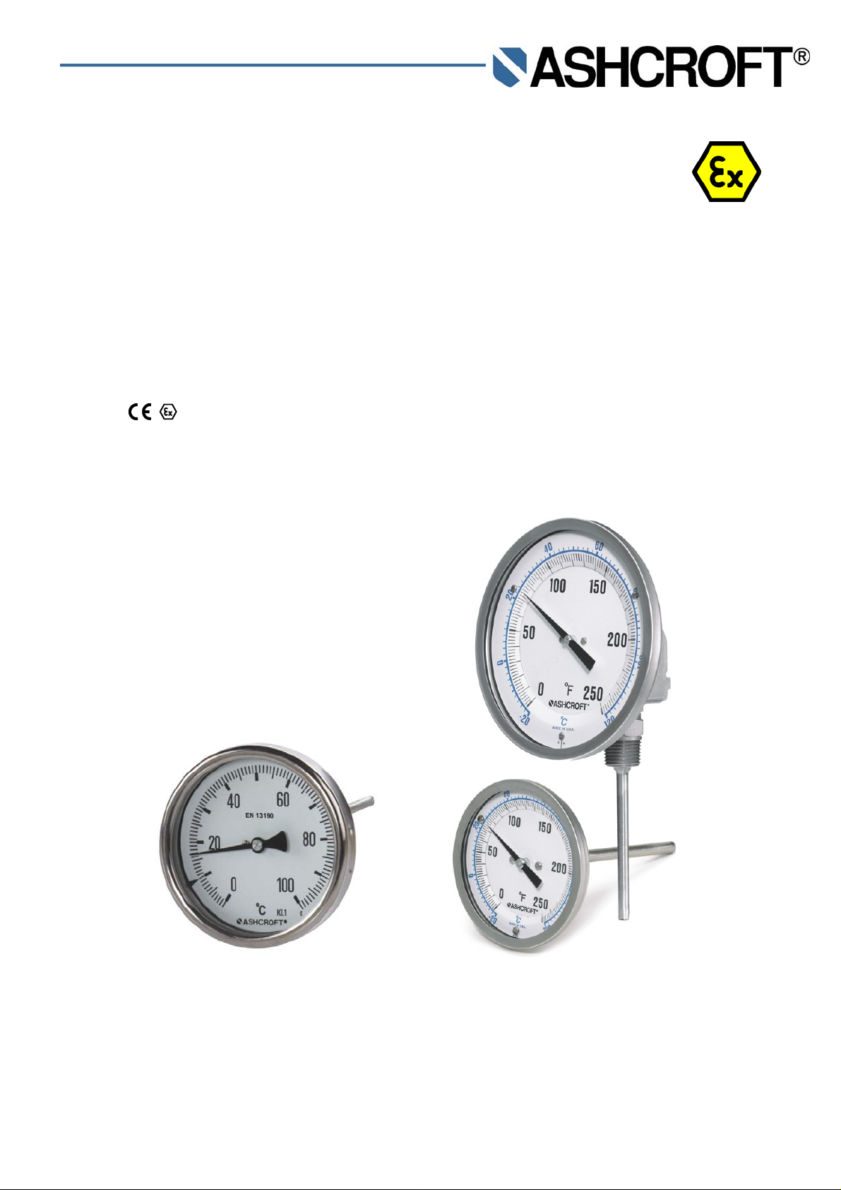
Bi-metal Thermometer Model A and E
(non-electrical device) in a configuration
- pursuant to ASME B40.200: 50=E#=###=ATEX or 50=ERT#=###=ATEX
- pursuant to EN 13190: ###=A#=###=ATEX or ##=ART#=###=ATEX
for explosion risk areas pursuant to Directive 94/9/EC (ATEX)
Marking
II 2 GD c Tx°C IP66
IM-BiM/ATEX-E-Rev 0 09/2011 Page 1 of 12
Page 2

Table of contents:
1
General remarks.........................................................................................................................................................3
1.1 Purpose of this Manual.........................................................................................................................................3
1.2 Symbols................................................................................................................................................................3
1.3 Limits of liability.....................................................................................................................................................3
1.4 Copyright...............................................................................................................................................................3
1.5 Warranty ...............................................................................................................................................................3
1.6 Manufacturer’s address, customer services.........................................................................................................3
2 Safety..........................................................................................................................................................................4
2.1 General sources of hazards..................................................................................................................................4
2.2 Use in accordance with intended purpose............................................................................................................4
2.3 Operator’s responsibility.......................................................................................................................................4
2.4 Staff qualifications (target group assessment) .....................................................................................................4
2.5 Signs/Safety markings..........................................................................................................................................4
2.6 Safety equipment..................................................................................................................................................4
2.7 Environmental protection......................................................................................................................................4
3 Use in explosion risk areas pursuant to Directive 94/9/EC (ATEX) ...........................................................................5
4 Technical data ............................................................................................................................................................5
5 Labeling on the device................................................................................................................................................5
5.1 Labeling on the device for explosion risk areas (ATEX).......................................................................................5
6 Construction and function...........................................................................................................................................5
6.1 Overview...............................................................................................................................................................5
6.2 Description of function..........................................................................................................................................5
6.3 Description of components...................................................................................................................................6
6.4 Accessories...........................................................................................................................................................6
7 Transport ....................................................................................................................................................................6
7.1 Safety....................................................................................................................................................................6
7.2 Transport inspection.............................................................................................................................................6
7.3 Storage .................................................................................................................................................................6
8 Mounting/Installation...................................................................................................................................................6
8.1 Safety....................................................................................................................................................................6
8.2 Preparations (requirements for the installation location)......................................................................................6
8.3 Mounting/Installation.............................................................................................................................................6
8.4 Starting up.............................................................................................................................................................7
9 Servicing.....................................................................................................................................................................8
9.1 Safety....................................................................................................................................................................8
9.2 Check on function, and recalibration....................................................................................................................8
9.3 Cleaning and maintenance...................................................................................................................................8
10
Faults....................................................................................................................................................................8
10.1 Safety ...............................................................................................................................................................8
10.2 Conduct in the event of faults...........................................................................................................................8
10.3 Fault table.........................................................................................................................................................8
10.4 Conduct following fault rectification..................................................................................................................8
11
Demounting, disposal...........................................................................................................................................9
11.1 Safety ...............................................................................................................................................................9
Page 2 of 12
Page 3

11.2 Demounting......................................................................................................................................................9
11.3 Disposal............................................................................................................................................................9
12
Appendix.............................................................................................................................................................10
12.1 Declaration of conformity................................................................................................................................10
12.2 Datasheets for bi-metal thermometers...........................................................................................................12
1 General remarks
1.1 Purpose of this Manual
This Operating Manual contains fundamental and essential advice to be followed for the installation,
operation and servicing of the device. It must be read without fail before assembly and start-up of the device
by the fitter, the operator and the specialist personnel responsible for the device. This Operating Manual
must be available at the point of use of the device at all times.
The following sections about general Safety information (2) and also the following specific advice regarding the
intended purposes (2.2) and through to disposal (11.3) contain important safety information which, if not followed, may
result in risks for people and animals, or to property and buildings.
1.2 Symbols
Warning!
This indicates a possibly hazardous situation where failing to follow advice may result in risks to people,
animals, the environment and buildings.
Information!
This emphasizes key information for efficient, fault-free operation.
1.3 Limits of liability
Failure to respect this safety information, the envisaged uses or the limit values relating to use indicated in the
technical data for the device may result in risk or to injury to people, the environment or the plant.
Claims for compensation for damage against the device supplier are excluded in such an eventuality.
1.4 Copyright
This Operating Manual may only be copied and passed on as a complete document without the special permission of
the publisher.
1.5 Warranty
For the product described here, we offer a warranty pursuant to Section 6 Guarantee in Respect of Defects in our
General Terms and Conditions of Delivery and Payment.
1.6 Manufacturer’s address, customer services
Ashcroft Instruments GmbH
Max-Planck-Strasse 1
D-52499 Baesweiler. Germany
Tel.: +49 (0) 2401/808-888
Fax.: +49 (0) 2401/808-999
E-mail: customer.service@ashcroft.com
Web: www.ashcroft.eu
Page 3 of 12
Page 4

2 Safety
2.1 General sources of hazards
Temperature gauges are generally a constituent part of a control and measurement system, and their failure can result
in hazardous situations. The selection of temperature gauge should be made in accordance with the rules set out in
EN 13190 or ASME B40.200.
2.2 Use in accordance with intended purpose
The devices are only to be used for the intended purpose as described by the manufacturer.
The devices are used for direct display of temperatures.
For each use scenario, the corresponding set-up regulations must be respected. If used in explosion risk areas, the
following conditions are to be respected.
2.3 Operator’s responsibility
Safety instructions for proper operation of the device must be respected. They are to be provided by the operator for
use by the respective personnel for installation, servicing, inspection and operation. Risks from electrical energy and
from the released energy of the medium, from escaping media and from improper connection of the device must be
eliminated. The details for this are to be found in the corresponding applicable set of regulations, such as DIN EN,
UVV (accident prevention regulations) and in sector-specific instances of use (DVWG, Ex-. GL, etc.) the VDE
guidelines and the regulations supplied by local utilities companies.
The device must be taken out of service and secured against inadvertently being restarted, if the presumption is that
risk-free operation is no longer possible (see Chapter 10: Faults).
Conversion works or other technical alterations to the device by the customer are not permitted. This also applies to
installation of spare parts. Possible conversations or alterations may only be carrie d out by the manufacturer.
The operational safety of the device is only guaranteed where it is used for its intended purpose. The specification of
the device must be adapted to the medium used in the plant. The limit values indicated in the technical data must not
be exceeded.
The safety information detailed in this Operating Manual, existing national regulations for accident prevention, and the
operator’s internal regulations regarding working, operations and safety must be respected.
The operator is responsible for all specified servicing, inspection and installation works being carried out by authorized
and qualified specialists.
2.4 Staff qualifications (target group assessment)
The device may only be installed and started up by specialist staff who are familiar with installation, start-up and
operation of the product.
Specialist staff are people who are able to assess the work assigned to them on the basis of their specialist training,
their knowledge and experience and their knowledge of the relevant standards, and can identify possible risks.
For devices in explosion-protected configuration, these staff must have been trained or instructed in, or be authorized
for, working on explosion-protected devices in potentially explosive plants.
2.5 Signs/Safety markings
The gauge and its surrounding packaging carry markings. These markings show the article number, measurement
range and manufacturer. The gauge can be provided with additional signs and safety markings advising on special
conditions:
Advice on calibration
Ex (for ATEX configuration)
2.6 Safety equipment
The window uses multi-layer safety glass.
2.7 Environmental protection
This device contains no environmentally hazardous components.
Page 4 of 12
Page 5

3 Use in explosion risk areas pursuant to Directive 94/9/EC (ATEX)
Area of use:
Bi-metal thermometers are intended for installation in pipes, tanks, plant and machinery to measure the temperatures
of gaseous and/or liquid materials. The requirements for the explosion area are limited to Zone I and II, Category 2,
Group II for gas and dust.
Permitted temperatures:
A temperature class is not specified, since no heating emanates from the device. The ambient temperature is limited
to the range -20 °C to 60 °C.
For the non-electrical part of the devices, the standards EN 13463-1, EN 13463-5 and EN 60079-0 are applicable with
regard to explosion protection. The relevant requirements of these standards are satisfied.
The documentation has been filed with TÜV-Nord-Cert (see declaration of conformity).
Labeling:
II 2 GD c Tx°C IP66
4 Technical data
The detailed technical information can be found in the documents in the Appendix, Chapter 12.
5 Labeling on the device
The label with the serial number and type designation is located on the outside right of the housing. The nature of the
subject characteristics is encoded in the type designation.
5.1 Labeling on the device for explosion risk are as (ATEX)
The label with the marking for explosion risk areas is located on the housing.
Type designation
###=A#=###=ATEX or ###=ART#=###=ATEX
50=E#=###=ATEX or 50=ERT#=###=ATEX
6 Construction and function
6.1 Overview
1 Bi-metal helix
2 Stem
3 Shaft
4 Process connection
5 Case
6 Pointer
7 Window
8 Ring
6.2 Description of function
The temperature is transferred through thermal conduction onto the bi-metal helix, which is firmly gripped on one side.
Due to its construction, using 2 metals with different coefficients of thermal expansion, it rotates proportionally to the
temperature change. This rotary motion is transferred via a shaft to the pointer. The angle of rotation for the complete
range is approx. 270°.
Page 5 of 12
Page 6

6.3 Description of components
6.3.1 Stem
The stem, with a diameter of 6-9.6 mm and a length of 63-1000 mm, contains the bi-metal helix on the side facing
away from the case. Its active length is approx. 50 mm. The stem must not be subjected to pressure without a
supplementary thermowell.
6.3.2 Dial with pointer
The gauge is equipped with a dial and pointer pursuant to EN 13190 or ASME B40.200.
Erläuterung, zusätzlich ein Hinweis:
6.3.3 Instrument connection
The instrument connection is located on the underside of the gauge and can be executed as a threaded or flanged
connector. Union instrument connections permit the case to be oriented according to the point of installation.
6.4 Accessories
Please contact the manufacturer regarding special tools and accessories.
7 Transport
7.1 Safety
The thermometer should be protected against the effects of knocks and impacts. The device should only be
transported in the packaging provided, to protect against glass breakage. The device should only be transported in a
clean condition (free from residues of measuring media).
7.2 Transport inspection
The delivery is to be checked for completeness and damage during transport. In the event of damage during transport,
the delivery is not to be accepted, or only accepted subject to reservation of the scope of the damage being recorded
and, if necessary, a complaint initiated.
7.3 Storage
The gauge is to be stored in dry, clean conditions, within a temperature range of -20 to +60 °C, protected against
direct exposure to sunlight and protected against impact damage.
8 Mounting/Installation
8.1 Safety
Thermowells must be used for all processes and flowing media subjected to pressure. They protect the thermometer
stem against corrosion and mechanical damage, and permit the thermometer to be removed without leaks.
8.2 Preparations (requirements for the installation location)
A check on suitability of the device and of the thermowell that may be required for the medium to be measured,
the arrangements in the scope of measurement range and the extent of the protection against special conditions
such as vibrations.
A bracket must be installed to support the gauge if the metering pip e is not able to provide adequate support.
The operating temperature range is -20°C to + 60 °C.
8.3 Mounting/Installation
Using appropriate accessories, the device can be installed on flat walls, mounting plates, on pipes or in panels or
boards.
Ex works, the device is supplied and calibrated fo r vertical installation.
If the installation location deviates from the vertical (max. ± 5°), the zero setting on the indicator must be corrected
(see 8.4.1 Zero point adjustment).
Page 6 of 12
Page 7

8.3.1 Every angle connection (optional)
Only adjust the every angle connection if this is necessary during fitting or
removal.
Use the every angle connection to place the sensor in the correct position
prior to installation, proceeding as follows:
Position the thermometer housing in a straight alignment (Position “C”)
Using the screws marked “A”, loosen until the joint can be turned freely
through 180° on the lower part of the housing and the sensor.
Hold the thermometer housing firmly with one hand, and with the other hand
turn the joint piece until the inner part of the joint is showing in the desired
direction of bend.
Firmly tighten the aforementioned Screws “A” again.
Loose the screws marked “B” and move the joint into the desired direction of
bend.
Firmly tighten the aforementioned Screws “B” again.
8.3.2 Process connection
Connection only to be undertaken by authorized and qualified specialist staff.
Use only with the mechanical process connection provided – regarding the configuration, see order code on the
device type label.
When connecting the device without using a thermowell, the pipes must be depressurized.
Do not allow any mechanical force to be applied to the stem; in particular, pay attention to matching the "S"
lengths of the thermometer and the thermowell, to avoid contact against the base of the thermowell.
A thermal transfer medium (heat conducting paste) in the thermowell improves the reaction time and reduces the
measurement error caused by the thermal transfer.
Safety notice: Only mount using the correct open-jawed wrench, and do not twist the device itself.
Do not insert moist or oily stems into hot thermowells.
8.4 Starting up
The precondition for start-up is correct installation. All connecting lines must be laid such that no mechanical
forces can act on the device.
Before start-up, the seal on the thermowell in the pipe must be checked.
8.4.1 Zero point adjustment
On thermometers with an external adjustment option, rotate using a screwdriver until the pointer is showing the
desired temperature on the scale.
On thermometers with a bayonet ring, remove the ring, take hold of the pointer using two fingers on the broader
part close to the pointer bearing, and use a small screwdriver to rotate the bearing by an estimated angle. Then let
go of the pointer and read off the value displayed. Repeat this operation until the desired value is being displayed.
Then seal the housing tightly again using the bayonet ring, the glass and the sealing ring.
Page 7 of 12
Page 8

9 Servicing
The device is maintenance-free. However, to ensure reliable operation and a long lifetime for the device, we
recommend that it is checked regularly.
9.1 Safety
When undertaking servicing work on the device fitted without a thermowell, the lines must be depressurized and the
plant secured against being switched on again.
9.2 Check on function, and recalibration
The check on function and recalibration is carried out at regular intervals, depending on the application. The precise
testing cycles should be adjusted in line with the operating conditions and ambient conditio ns.
Check on display.
Check the thermowell for damage and seal.
9.3 Cleaning and maintenance
Cleaning is carried out using a non-aggressive cleaning agent, respectin g the protection category of the device.
10 Faults
10.1 Safety
Defective or faulty gauges put the operational safety and process safety of the plant at risk, and can lead to a risk or
injury to persons, the environment or the plant.
10.2 Conduct in the event of faults
All defective or faulty devices are to be taken out of service. If a repair is required, the device is to be sent directly to
our Repairs Department. We request that all returns of devices are agreed with our Service Department.
10.3 Fault table
Possible situations indicating a fault:
Jerky or random movement of the pointer
No correspondence between the measured value being displayed and actual temperature
Bent or loose pointer
Cracked window
Damage to housing
Extended storage at temperatures above 60 °C
In these instances, replacement of the gauge is always required.
10.4 Conduct following fault rectification
See Chapter 8 Mounting/Installation
Page 8 of 12
Page 9

11 Demounting, disposal
11.1 Safety
Residues of measuring media in and on removed gauges can constitute a risk to people, the environment
and equipment. Adequate precautionary measures are to be adopted. If necessary, the devices are to be
cleaned thoroughly (see advice in safety data sheets).
11.2 Demounting
When undertaking servicing work on the device fitted without a thermowell, the lines must be depressurized and
the plant secured against being switched on again.
Demount the gauge using a suitable tool.
11.3 Disposal
Please help to protect the environment and dispose of or recycle the devices and components used in
accordance with the applicable regulations.
Page 9 of 12
Page 10

12 Appendix
12.1 Declaration of conformity
Page 10 of 12
Page 11

Page 11 of 12
Page 12

12.2 Datasheets for bi-metal thermometers
More detailed datasheets are available direct from the manufacturer (see 1.6 Manufacturer address, customer
services).
The table below contains an overview of the individual documents.
Model Description Document
A Bi-metal thermometer, Model A, pursuant to EN 13190 G2.BIM-EN
E Bi-metal thermometer, Model E, pursuant to ASME B40.200 G2.BIM-ASME
ART Bi-metal thermometer, Model ART, with stepped stem G2.BIMRT
ERT Bi-metal thermometer, Model ERT, with stepped stem G2.BIMRT
Page 12 of 12
 Loading...