

Page 1
All speci fications are subject to change without notice.
All sales subject to standard terms and conditions.
©2019 Ashcroft Inc. dxldp_transmitter_ds_RevB_04-19
ashcroft.com
info@ashcroft.com
1.800.328.8258
Data Sheet
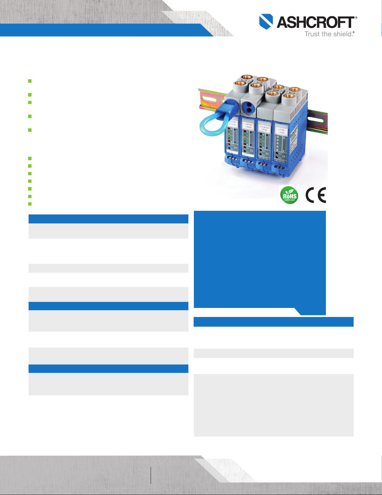
DXLdp Ultra-Low Differential Pressure Transmitter
FEATURES
The exclusive patented Ashcroft® SpoolCal™ actuator
provides in-place system calibration
2:1 range turndown (OPT.)
Front access test jacks provide on-line signal
reference without removing wiring
LED range status indicators for instant
troubleshooting information
Si-Glas™ technology enables precise measurement
and control of very low pressures
TYPICAL USES
HVAC/R
Bio-pharm
Bio-tech
Room pressurization and control
Velocity pressure
Critical environments
Building energy management/comfort control systems
DXLdp
Pressure Transmitter
PERFORMANCE SPECIFICATIONS
Reference
Temperature:
Accuracy Class: Three Options: ±0.25%, ±0.5%, ±1.0% of span
Stability: ≤ ±0.25% of span/year
Media Compatibility: Clean, dry and non-corrosive gas
Standard Response
Time:
ENVIRONMENTAL SPECIFICATIONS
Temperature Limits: Storage:
Thermal Coefficients:
Humidity Effects:
FUNCTIONAL SPECIFICATIONS
Max. Static (Line)
Pressure:
25 psi
Mounting Position
Effect:
70°F±2ºF (21°C±1ºC)
(Terminal Point Method: includes non-linearity,
hysteresis, non-repeatability, zero offset and span
setting errors)
NOT FOR USE ON LIQUIDS
250ms
Operating:
Compensated:
Zero & Span: ±0.02% of span/°F
(From 70°F (21°C) reference temperature)
No performance effect at 10-95% R.H.
noncondensing
Proof:
15 psid
Mounting Position Effect easily corrected with zero
potentiometer
≥0.5 IWC 0.1% span/g
<0.5 IWC 0.25% span/g
–40°F to 180°F (–40°C to 82°C)
–20°F to 160°F (–29°C to 71°C)
35°F to 135°F (1.6°C to 57°C)
Burst:
25 psid
KEY BENEFITS
• Broad temperature capability
• DIN rail mount dramatically reduces installation
and calibration costs
• CE standard with all outputs
• On-board voltage regulation allows use of lower
cost, unregulated power supply
• SpoolCal™ process valve actuator provides
in-place system calibration without disturbing
process tubes
ELECTRICAL SPECIFICATIONS
Potentiometers: Front accessible, non-interactive
Supply Current: <10 mA for Voltage
Warm-up Time: 5sec Max. to meet stated specifications from
Output Signal:
4-20 mA (2 wire)
1-5 Vdc (3 wire)
1-6 Vdc (3 wire)
0-5 Vdc (3 wire)
0-10 Vdc (3 wire)
Circuit Protection: Reversed wiring protection
Zero: ±5% F.S.
Span: ±3% F.S.
initial Power-up
Power:
12-36 Vdc
12-36 Vdc
12-36 Vdc
12-36 Vdc
12-36 Vdc
Output signal is independent of power supply
changes: 12-36 Vdc range without effect on
output signal
of 41
Page 2
All speci fications are subject to change without notice.
All sales subject to standard terms and conditions.
©2019 Ashcroft Inc. dxldp_transmitter_ds_RevB_04-19
ashcroft.com
info@ashcroft.com
1.800.328.8258
Data Sheet
DXLdp Ultra-Low Differential Pressure Transmitter
PHYSICAL SPECIFICATIONS
Electrical Connection: Screw Termination
Enclosure Rating: NEMA 1 case
Mounting:
Pressure
DIN rail types EN50022, 35 and 45
¹⁄8
NPT Female, ¹¹⁄
64
barbed Male
Connections:
Weight: 4.5 oz
WETTED MATERIAL
Media
Clean, dry air/gases compatible with Aluminum, Titanium, PBT, Buna,
Glass, Gold, Silicone Rubber, Silicon, Silicone RTV and Brass
NOT FOR USE ON LIQUIDS
NON-WETTED
Housing
Glass-filled polycarbonate (UL94-V-1)
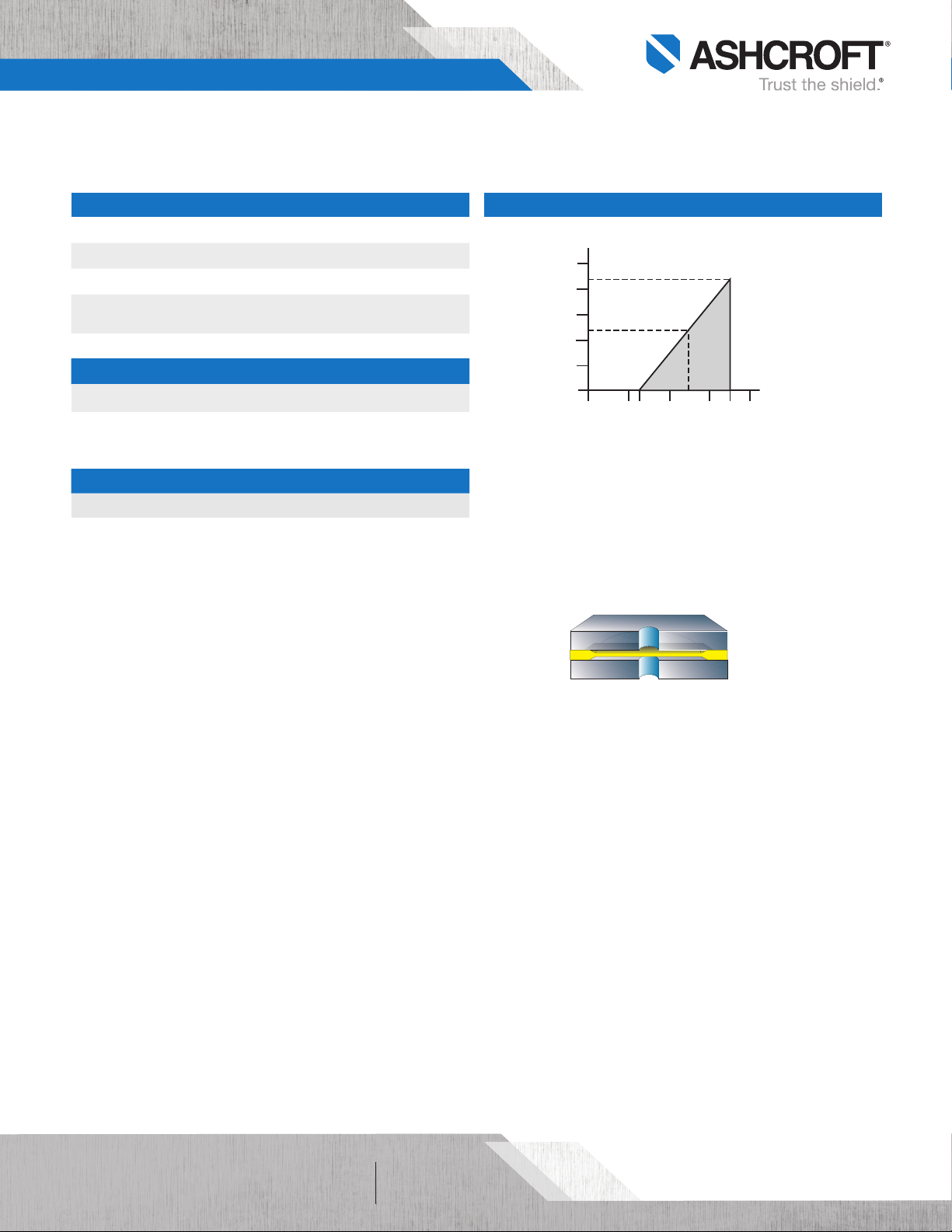
LOAD LIMITATIONS 4-20 mA OUTPUT ONLY
1,250
1,091
1,000
750
545
500
250
Loop Resistance ()
0
10
0
Featuring a highly reliable variable capacitance sensor using the patented
®
Ashcroft
Si-Glas™ sensor. This ultra-thin single crystal diaphragm provides
12 20 30 36
V
= 12V+ [0.022A*(R L)]
min
*includes a 10% safety factor
RL = RS + R
RL = Loop Resistance (ohms)
RS = Sense Resistance (ohms)
RW = Wire Resistance (ohms)
OPERATING
REGION
24
W
40
inherent sensor repeatability and stability.
Sensor Cross Section
The silicon diaphragm sensor has no glues or
other organics to contribute to drift or
mechanical degradation over time.
of 42
Page 3

All speci fications are subject to change without notice.
All sales subject to standard terms and conditions.
©2019 Ashcroft Inc. dxldp_transmitter_ds_RevB_04-19
ashcroft.com
info@ashcroft.com
1.800.328.8258
Data Sheet
DXLdp Ultra-Low Differential Pressure Transmitter
ORDERING CODE
Model
DX3 - DXLdp Series, ±0. 25% of span, ±0.02% span T.C. /°F DX3
DX5 - DXLdp Series, ±0.50% of span, ±0.02% span T.C. /°F
DX7 - DXLdp Se ries, 1.00% of span, ±0.02% span T.C. /°F
Pressure Connection
F01 - ¹⁄
NPT Fema le F01
8
MB2 - ¹¹⁄64 Barbed Male
Output Signal
05 - 0-5 Vdc
10 - 0-10 Vdc
15 - 1-5 Vdc
16 - 1-6 Vdc
42 - 4-20 mA 42
Eletrical Termination
ST - Screw Terminal ST
Pressure Range
Unidirectional Ranges (differential)
P1IW - 0.10 IWD
P25IW - 0.25 IWD
P5IW - 0.50 IWD P5IW
1IW - 1.00 IWD
1P5IW - 1.50 IWD
2IW - 2.00 IWD
2P5IW - 2.50 IWD
3IW - 3.00 IWD
5IW - 5.00 IWD
10IW - 10.00 IWD
15IW - 15.00 IWD
20IW - 20.00 IWD
25IW - 25.00 IWD
50IW - 50.0 0 IWD
Bi-directional Ranges
P05IWL - ±0.05 IWD
P1IWL - ±0.10 IWD
P25IWL - ±0.25 IWD
P5IWL - ±0.50 IWD
P75IWL - ±0.75 IWD
1IWL - ±1.00 IWD
2IWL - ±2.00 IWD
2P5IWL - ±2.50 IWD
3IWL - ±3.00 IWD
5IWL - ±5.00 IWD
10IWL - ±10.00 IWD
25IWL - ±25.00 IWD
Opti ons (i f indicating an option(s) must i nclude an “X”) –X__
21 - 2:1 Turndown
CL - Custom pressure range calibration
DL - LED range status indicators (includes front acce ss test jacks)
NH - SS tag
NL - Front access test jacks (no LED indication)
NN - Paper t ag
PV - SpoolCal™ process valve actuator PV
RH - 9 pt. NIST traceab le calibration re port (O PT. for DX7/1.00% accuracy ve rsion, STD. for DX3 and DX5)
X1 - Fast response time (10 ms)
X2 - Slow response time (1 sec)
Example:
DX3 F01 42 ST P5IW –XPV
of 43
Page 4

All speci fications are subject to change without notice.
All sales subject to standard terms and conditions.
©2019 Ashcroft Inc. dxldp_transmitter_ds_RevB_04-19
ashcroft.com
info@ashcroft.com
1.800.328.8258
Data Sheet
DXLdp Ultra-Low Differential Pressure Transmitter
3.18
DIMENSIONS
For reference only, consult Ashcroft for specific dimensional drawings
SpoolCal and LED (OPT.)
5.29
+
Model: DXLdp
3.18
Zero
Span
Zero
V+ V– Out
+P
Test
–P
–
3.92
Basic Unit
Model: DXLdp
3.92
4.96
0.89
Span
Zero
V+ V– Out
0.89
of 44
 Loading...