

Page 1
Installation and Maintenance Instructions for
3.32
(84)
4.03
(102)
0.22
(6)
3.26
(83)
Ø 0.28 X 3 HOLES
(7)
1/4 NPT FEMALE
HIGH PRESSURE PORT
1/4 NPT FEMALE
LOW PRESSURE PORT
HL
2.27
(58)
1.25
(32)
2.77
(70)
2.99
(76)
0.25
(6)
1.55
(39)
Ø 2.31
(59)
7.16
(182)
3/4 NPT
5.20
(132)
3.62
(92)
2.18
(55)
0.32
(8)
4.37
(111)
1.37
(35)
Ø 0.28 x 3 HOLES
(7)
3.09
(78)
Ø 2.31
(59)
1.93
(49)
1/4 NPT FEMALE
LOW PRESSURE PORT
1/4 NPT FEMALE
HIGH PRESSURE PORT
HL
Ø 3.90
(99)
0.03
(1)
3.58
(91)
0.31
(8)
7.78
(198)
1.55
(39)
3/4 NPT
2 HOLES
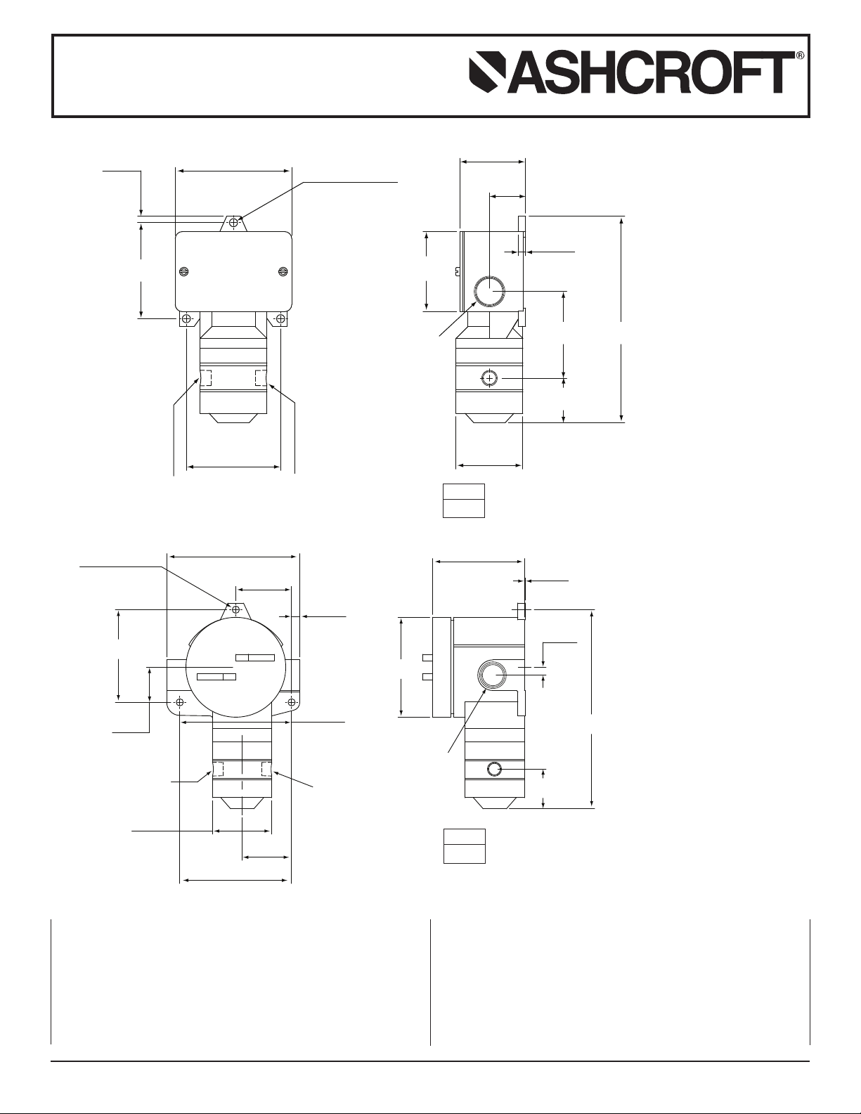
D400 & D700 ASHCROFT®Snap Action
Switches for Differential Pressure Control
D400
D700
INTRODUCTION
The Ashcroft
and C.S.A. approved control device which features a mechanical
snap action switch. Controllers are available for operation on
various pressure differentials with fixed or variable switching differentials. Also, manual reset types are available for operation on
increasing or decreasing pressure. The manual reset types
remain tripped until reset by pressing a button on the top of the
enclosure. The standard electrical switch is SPDT and is avail-
© 2012 Ashcroft Inc., 250 East Main Street, Stratford, CT 06614-5145, USA, Tel: 203-378-8281, Fax: 203-385-0499, www.ashcroft.com
All sales subject to standard terms and conditions of sale. I&M009-10007- (250-2248E) 10/12
®
differential pressure switch is a precision built U.L.
3.6 lb
(1.6 kg)
4.5 lb
(2.0 kg)
STANDARD RANGES
15, 30, 60, 100, 200, 400, 600 psid
able with various electrical characteristics. Two SPDT switch elements mounted together are available except on variable deadband and manual reset types. Various wetted material constructions for compatibility with a wide range of pressure media may
be obtained.
The Ashcroft snap action temperature switch is furnished in the
standard NEMA 4 and explosion proof NEMA 7 and 9 enclosure
styles. Both enclosures are epoxy coated aluminum castings.
Page 2
Installation and Maintenance Instructions for
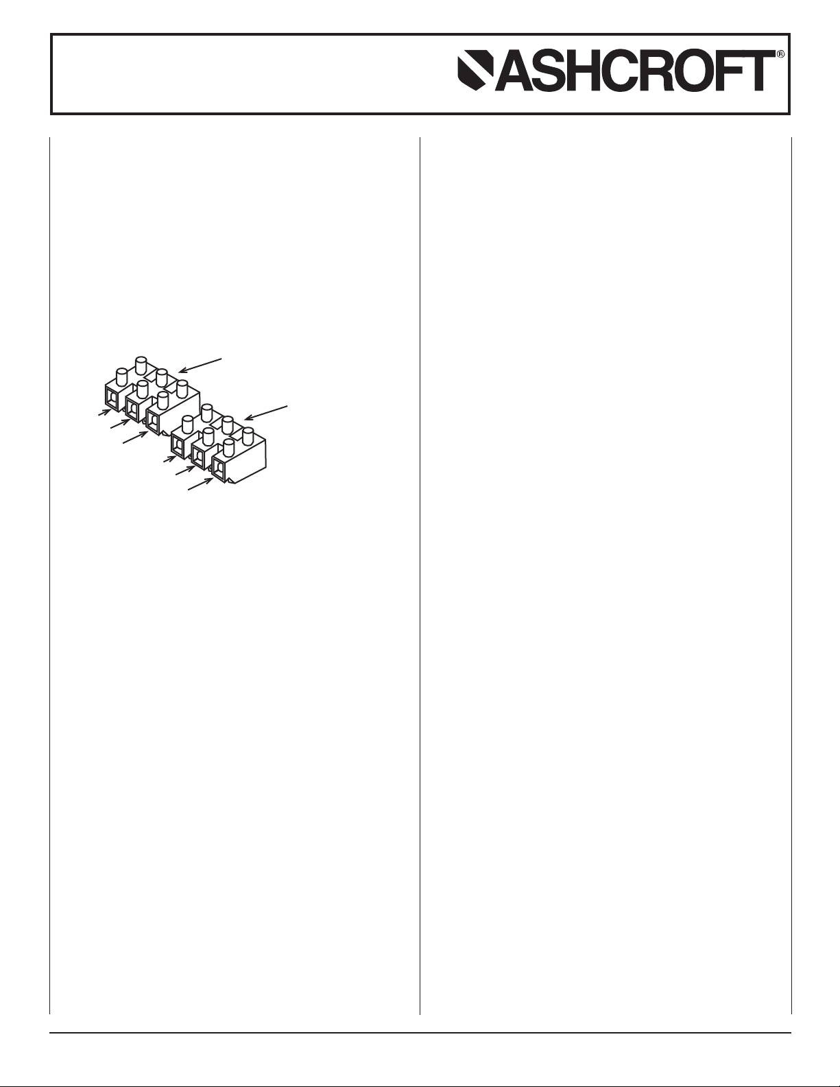
TERMINAL BLOCK
FRONT SWITCH
TERMINAL BLOCK
REAR SWITCH
NC
NO
C
NC
NO
C
D400 & D700 ASHCROFT®Snap Action
Switches for Differential Pressure Control
INSTALLATION
These controls are precision instruments and should never be
left with internal components exposed. After installation ensure
that covers are in place and conduit openings are closed.
MOUNTING D400 AND D700 SERIES
There are three holes external to the enclosures for surface
mounting. The locations of these holes is shown on the general
imension drawing. The controls may also be mounted directly
d
on the pressure line using the pressure connections.
ELECTRICAL CONNECTIONS
Remove cover
D400 Series – two screws hold cover to enclosure
D700 Series – cover unscrews
CONDUIT CONNECTIONS
Note – It is recommended that Teflon
®
tape or other sealant be
used on conduit, bushing or plug threads to ensure integrity of
the enclosure.
D400 Series standard – one
D700 Series standard – two
3
⁄
4 NPT conduit hole right side.
3
⁄
4 NPT conduit holes with one
permanent plug. NEMA 7 & 9 enclosures require proper conduit
seals and breathers as per the National Electrical Code.
D400 & WT700 Series – XJL variation – two
holes with two
D400 Series – XJK variation – two
3
1
⁄
4 to
⁄
2 NPT reducing bushings.
3
⁄
4 NPT conduit holes.
3
⁄
4 NPT conduit
D400 SERIES
SPDT – Wire directly to the switch according to circuit require-
ments. On controls with pilot lights, wire lights according to circuit diagram on the inside of the cover. See special wiring
instruction tag for single switches with two pilot lights and dual
switches with one or more pilot lights.
2-SPDT – Dual switching elements consist of two SPDT switches
mounted together in a bracket. The switches are calibrated to have
simultaneous operation within 1% of range either on increasing
or decreasing pressure, but not in both directions. Wire directly
to the front and rear switch according to circuit requirements.
Leads provided on rear switch and leads provided for hermetically sealed switch components are color coded as follows:
Common – White
Normally Closed – Red
Normally Open – Blue
D700 SERIES
SPDT – Wire directly to the switch according to circuit
requirements.
-SPDT – Wire to front switch terminal block (left) and rear
2
switch terminal block (right) as marked. Strip insulation
5
⁄
16˝,
insert in proper terminal connector and tighten clamping screw
to secure.
ADJUSTMENT OF SETPOINT
D400 & D700 Series – A single setpoint adjustment nut (
7
⁄
8˝) is
located centrally at the bottom on the inside of the enclosure.
The direction of turning is indicated on a label affixed to the
inside of the control enclosure.
A typical calibration procedure would be as follows:
Static Working Pressure – 600 psig
Adjustable Differential Range – 30/200 psid
Differential Setpoint – 150 psi above static working
pressure
Simultaneously raise the high and low side pressure to 600
psig. Maintain the low side pressure at 600 psig. Raise the high
side pressure to 750 psig to obtain 150 psi differential.
Turn the adjustment nut until the switch changes mode at 150
psi differential. When the setpoint has been achieved, raise and
lower the high side pressure to ensure that the differential setpoint is correct.
D450 and D750 VARIABLE DEADBAND SWITCHES
Deadband is varied by rotating the wheel on the precision
switch. When viewed from the front of the enclosure, rotation to
the left increases deadband – rotation to the right decreases
deadband. Letters on the wheel may be used as a reference.
Deadbands obtainable will vary from 2% to 9% of pressure
range depending on range segment and the type of diaphragm.
ADJUSTMENT OF SETPOINT
As received, the differential pressure switch will normally be set
to approximately 90% of range. Rotate the wheel on the MICRO
SWITCH all the way to the right. This will provide the smallest
deadband. Pressurize the system to the required setpoint and
turn the adjustment nut until the switch changes mode. Lower
the pressure to reset the switch. Rotate the wheel on the
MICRO SWITCH until the desired deadband is obtained. The
upper setpoint will be changing upward with this adjustment.
Lower the pressure to reset the switch. Increase the pressure to
the desired setpoint and turn the adjustment nut until the switch
changes mode. Lower the pressure and check the reset point
and deadband.
Note – As indicated above, adjustment of setpoint is made by
7
use of
⁄
8˝ nut. The precision switch element mounting screws
and bracket adjusting screw are factory sealed and should not
be tampered with.
See SPDT instructions for pilot light hook-up.
© 2012 Ashcroft Inc., 250 East Main Street, Stratford, CT 06614-5145, USA, Tel: 203-378-8281, Fax: 203-385-0499, www.ashcroft.com
All sales subject to standard terms and conditions of sale. I&M009-10007- (250-2248E) 10/12
 Loading...