

Page 1
Data Sheet
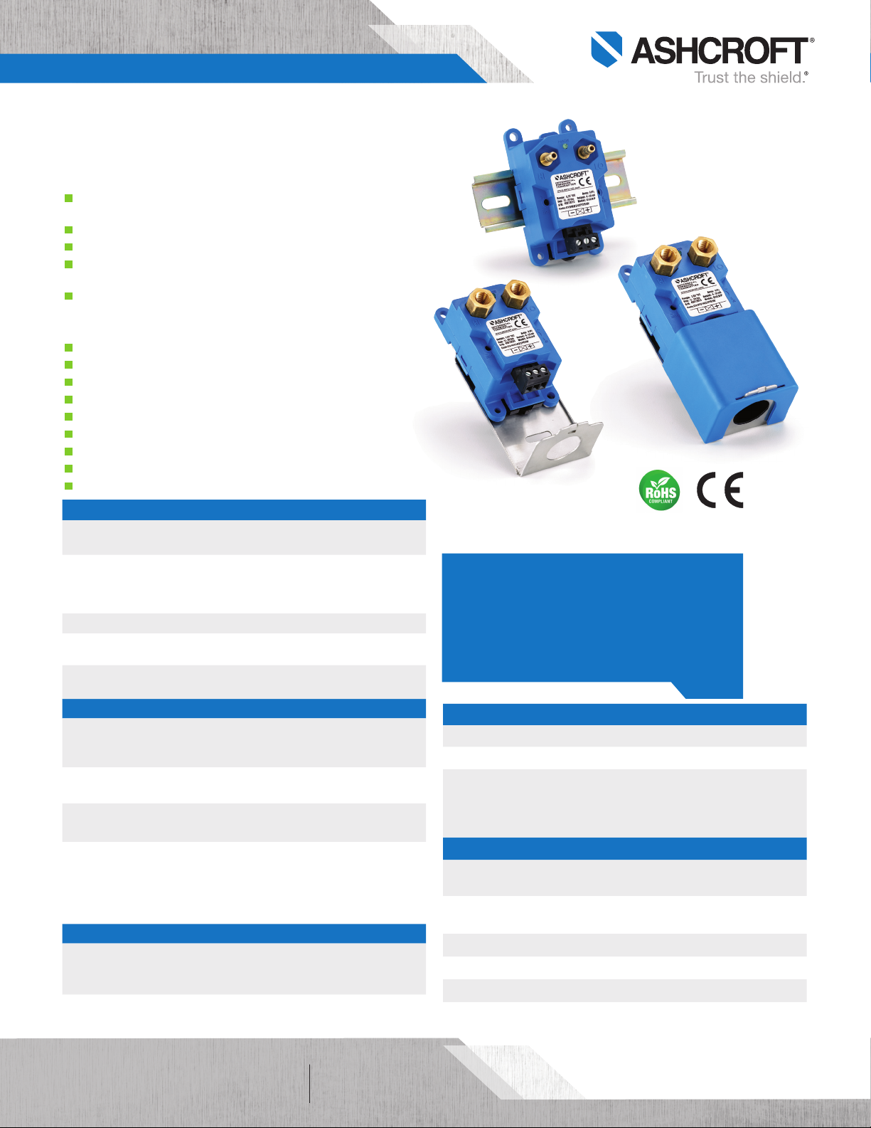
CXLdp Differential Pressure Transmitter
FEATURES
Rugged ABS package capable of DIN rail or
panel mounting
LED power status indicator
Detachable Euro style terminal block
22 pressure ranges (STD.) all capable of
withstanding 15 psi
Unidirectional and Bidirectional ranges
TYPICAL USES
Fume Hood Control
Building/Comfort Control System
Building Energy Management Systems
HVAC/R
Critical Environments
Fan Monitoring
Duct Flow
Clean Room
Filter Monitoring
PERFORMANCE SPECIFICATIONS
Reference
Temperature:
Accuracy Class: ±0.25%, ±0.4%, ±0.8% of span
Stability: ≤±0.25% of span/year at reference conditions
Media Compatibility: Clean, dry and non-corrosive gas
Standard Response
Time:
ENVIRONMENTAL SPECIFICATIONS
Temperature
Limits:
Thermal Coefficients:
Humidity Effects:
CE Marked:
FUNCTIONAL SPECIFICATIONS
Max. Static (Line)
Pressure:
25 psi
Mounting Position
Effect:
70°F ±2°F (21°C ±1°C)
(Terminal Point Method: includes non-linearity,
hysteresis, non-repeatability, zero offset and span
setting errors)
NOT FOR USE ON LIQUIDS
250ms
Storage:
Operating:
Compensated:
Zero & Span: ±0.03% of span/°F
(From 70°F (21°C) reference temperature)
No performance effect at 10-95% R.H.
noncondensing
Per DoC
EMC Directive 2014/30/EU
IEC/EN 61326-1:Edition 1.0 Industrial
IEC/EN 61326-2-3:Edition 1.0 Annex BB Industrial
RoHS: 2011/65/EU
Proof:
15 psid
±1% of span/g
(Calibration in vertical position is STD.)
–40°F to 180°F (–40°C to 82°C)
0°F to 160°F (–17°C to 71°C)
35°F to 130°F (1.6°C to 54°C)
Burst:
25 psid
CXLdp
Pressure Transmitter
KEY BENEFITS
• Broad temperature capability
• High performance ASIC based electronics
• Superior long-term stability and repeatability
• 3 year warranty
ELECTRICAL SPECIFICATIONS
Circuit Protection: Reverse polarity and miswire protected
Potentiometers: Zero & Span: ±5% of span (Externally accessible)
Voltage Output:
4-20 mA (2 wire)
0-5 Vdc (3 wire)
0-10 Vdc (3 wire)
PHYSICAL SPECIFICATIONS
Pressure
Connections:
Electrical
Connection:
Visual Indicator:
Weight:
Mounting:
Enclosure Rating:
Supply Voltage: Supply Current:
12-36 Vdc 21.5 mA
11.5-36 Vdc or 24 Vac (±20%) 4.5 mA
14-36 Vdc or 24 Vac (±20%) 6 mA
¼ brass barbed fittings (male)
¹⁄8 NPT Female brass
Euro style pluggable terminal block accepts
12-26 gauge wire
LED
Approx. 2.5 oz
Threaded fastener and 35mm DIN rail mount
NEMA 1, Fire-retardant ABS (meets UL94-5VA)
All speci fications are subject to change without notice.
All sales subject to standard terms and conditions.
©2019 Ashcroft Inc. cxldp_transducer_ds_RevD_03-19
of 31
ashcroft.com
info@ashcroft.com
1.800.328.8258
Page 2
Data Sheet
40
SENSOR CROSS SECTION
"B2" 1/4 BARB FITTINGS
1.45
ASSEMBLED WITH
101A213-01 CONDUIT KIT
CXLdp Differential Pressure Transmitter
WETTED MATERIAL
Media
Clean, dry air/gases compatible with Aluminum, Titanium, PBT, Buna,
Glass, Gold, Silicone Rubber, Silicon, Silicone RTV and Brass
NOT FOR USE ON LIQUIDS
NON-WETTED
Housing
Fire-retardant ABS (Meets UL 94-5VA)
LOAD LIMITATIONS 4-20 mA OUTPUT ONLY
1250
1045
1000
750
500
250
LOOP RESISTANCE (Ω)
0
10
0
LOOP SUPPLY VOLTAGE (Vdc)
V
= 12V+ [0.022A*(RL)]
min
*includes a 10% safety factor
RL = RS + R
RL = Loop Resistance (ohms)
RS = Sense Resistance (ohms)
RW = Wire Resistance (ohms)
OPERATING
REGION
12 20 30 36
W
Featuring a highly reliable variable capacitance sensor using the patented
Ashcroft® Si-Glass™ sensor. This ultra-thin single crystal diaphragm
provides inherent sensor repeatability and stability.
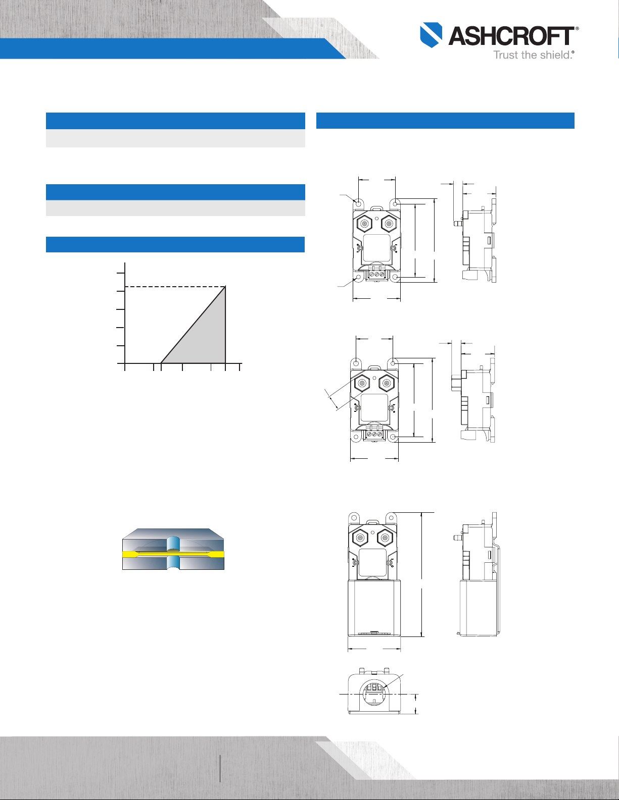
DIMENSIONS
For reference only, consult Ashcroft for specific dimensional drawings
“MB2” ¼ BARBED FITTINGS
1.45
Ø0.20
POWER
HI LO
ZERO
SPAN
2.90
3.33
Ø0.16
1.89
“F01” 1⁄8 NPT FEMALE FITTINGS
POWER
0.56
HI LO
ZERO
2.90
SPAN
3.33
1.89
ASSEMBLED WITH 101A213-01
½˝ PLENUM/CONDUIT KIT
0.36
1.32
0.35
1.32
The silicon diaphragm sensor has no glues or
All speci fications are subject to change without notice.
All sales subject to standard terms and conditions.
©2019 Ashcroft Inc. cxldp_transducer_ds_RevD_03-19
Sensor Cross Section
other organics to contribute to drift or
mechanical degradation over time.
ashcroft.com
info@ashcroft.com
1.800.328.8258
POWER
HI LO
ZERO
2.06
SPAN
4.85
Ø0.88
0.78
of 32
Page 3

Data Sheet
CXLdp Differential Pressure Transmitter
ORDERING CODE Example:
Model
CX3 - CXLdp Series, ±0.25% of span, ± 0.03% of span T.C. /°F
CX4 - CXLdp Ser ies, ±0.40% of span, ± 0.0 3% of span T.C. /°F CX4
CX8 - CXLdp Ser ies, ±0.80% of span, ± 0.03% of span T.C. /°F
Pressure Connection
F01 - ¹⁄8 NPT Fema le
MB1 - Board level only, no housing (cons ult facto ry)
MB2 - ¼ Barb ed Male MB2
Output Signal
10 - 0-10 Vdc (includes user sele ctable 0-5 Vdc output)
42 - 4-20 mA 42
Pressure Range
Unidirectional Ranges (differential)
P1IW - 0.1 IWD
P25IW - 0.25 IWD P25IW
P5IW - 0.50 IWD
P75IW - 0.75 IWD
1IW - 1.00 IWD
2IW - 2.00 IWD
2P5IW - 2.50 IWD
3IW - 3.00 IWD
5IW - 5.00 IWD
10IW - 10.00 IWD
15IW - 15.00 IWD
25IW - 25.00 IWD
Bi-directional Ranges
P1IWL - ±0.10 IWD
P25IWL - ±0.25 IWD
P5IWL - ±0.50 IWD
1IWL - ±1.00 IWD
2IWL - ±2.00 IWD
2P5IWL - ±2.50 IWD
3IWL - ±3.00 IWD
5IWL - ±5.00 IWD
10IWL - ±10.00 IWD
15IWL - ±15.00 IWD
Opti on (if i ncluding an optio n(s) mu st include an “X’’) –X__
3P - 3 Point ca librati on data (fo r CX4 and CX8 only)
AH - Plenum/condui t kit packaged with CXLdp
NH - SS tag
NN - Paper t ag
RH - 9 pt. NIST traceab le calibration re port (O PT. for CX4 and CX8 only, standard for CX3) RH
CX4 MB2 42 P25IW –XRH
All speci fications are subject to change without notice.
All sales subject to standard terms and conditions.
©2019 Ashcroft Inc. cxldp_transducer_ds_RevD_03-19
of 33
ashcroft.com
info@ashcroft.com
1.800.328.8258
 Loading...