

Page 1
Data Sheet
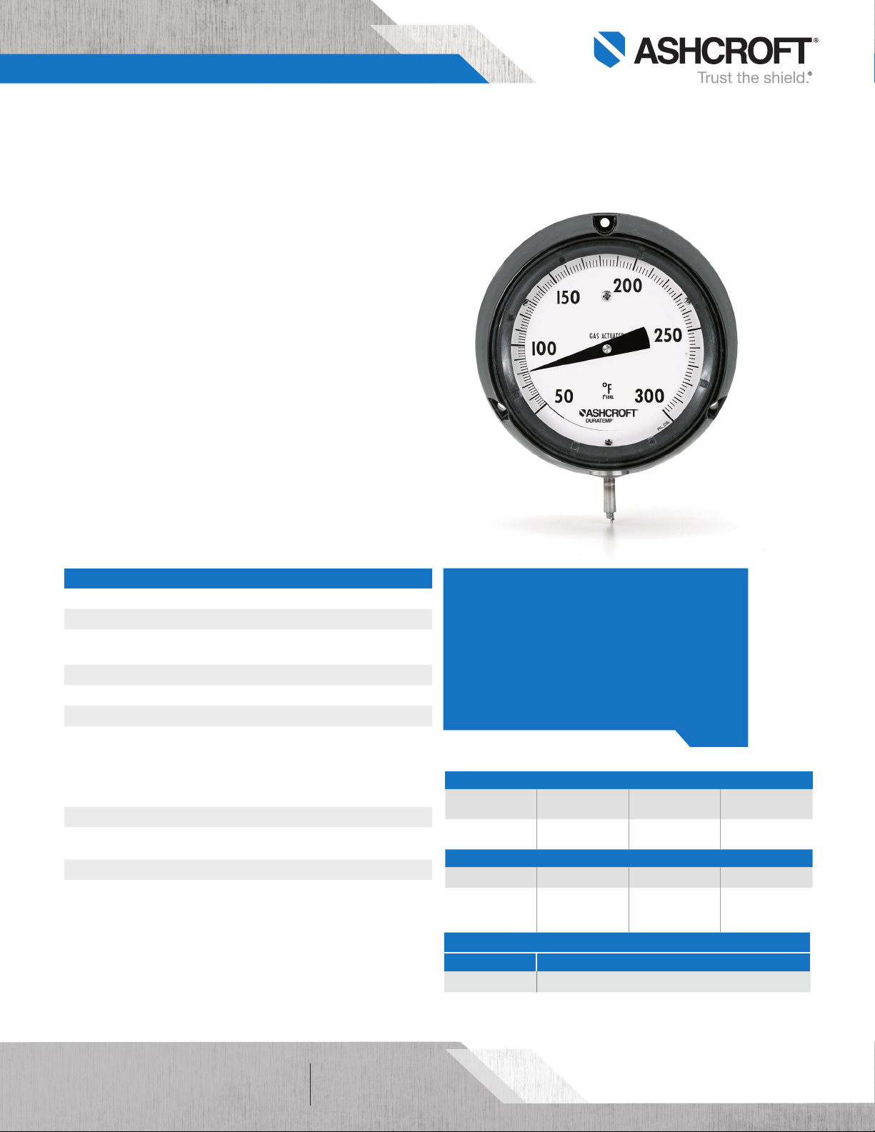
C-600H-45 Duratemp® Thermometer
FEATURES
Extreme resistance to shock and vibration
Exclusive movementless design eliminates wear and
increases product life
No head or elevation error due to bulb placement
Maxivision® dial for precise readings
(minimize parallax reading errors)
Hermetically sealed
Gas-operated molecular sieve
TYPICAL USES
Offshore oil rigs
Chemical and petrochemical plants
Water and wastewater temperature control
Pulp and paper
Refineries
Power
General industrial
Equipment skids
HVAC
Pharmaceutical/biotech
Food and beverage
C-600H-45
41⁄2˝ dial size
SPECIFICATIONS
Accuracy: ±1% of span
Size: 41⁄2˝
Range: -320°F/200°F to 400°F/1200°F
(-200°C/100°C to 200°C/650°C)
Over Range: 125% of span
Mounting & Connection: Surface/Lower
Bulb Size: 3˝ Long x 3⁄8˝ O.D.
Bulb Style: 12˝ Bendable extension with 1⁄2 NPT union connection
Plain bulb with rigid extension no union
Plain bulb with rigid extension 1⁄2 NPT union on armor
18˝ Bendable extension with 1⁄2 NPT union connection
24˝ Bendable extension with 1⁄2 NPT union connection
Line Length: 5ft to 80ft in standard increments
Dial: Maxivision® anti-parallax dial, black markings on
a white dial
Head/Elevation Error: None
Pointer: Black, aluminum
KEY BENEFITS
• Phenolic case
• Threaded ring for easy glass replacement or
pointer adjustment
• Extremely versatile for use on many
applications where dust or moisture is present
• 5 year limited warranty
THERMAL SYSTEM
Bulb/Bendable ext.
Material
316 SS
NON-WETTED COMPONENTS
Window Case Ring Back Cover
Glass,
Safety glass,
Acrylic
Version Ambient
Dry -13°F (-25°C) to 160°F (71°C)
Armor Material Capillary Material Connection Material
AISI 302 Spring
Armor
Phenolic
TEMPERATURE LIMITS
316 SS 303 SS
Polycarbonate
threaded ring
Polycarbonate
All specifications are subject to change without notice.
All sales subject to standard terms and conditions.
©2019 Ashcroft Inc. 600H-45_Duratemp_ds1.0, Rev. C, 04 /19
of 41
ashcroft.com
info@ashcroft.com
1.800.328.8258
Page 2
Data Sheet
C-600H-45 Duratemp® Thermometer
ORDERING CODE Example:
Case Style
C-600H-45-C60 - 4½˝ case size, phenolic hermetically sealed,
surface mount, lower connection
Bulb Style (See Note 1 below)
B01 - 12˝ Bendable extension with 1⁄2 NPT union connection B01
B03 - Plain bulb with rigid extension, no union
B08 - Plain bulb with rigid extension, 1⁄2 NPT union on armor
B17 - 18˝ Bendable extension with 1⁄2 NPT union connection
B18 - 24˝ Bendable extension with 1⁄2 NPT union connection
Armor Style
A1 - SS spring A1
Line Length (Capillary length is measured from bottom of case to top of bulb extension)
L01 - 5´ L01
L03 - 10´
L07 - 20´
L09 - 30´
L13 - 50´
L19 - 80´
Ranges (coding example, see range table on page 3 for all standard ranges)
AB - –320/200°F AB
Options (If choosing an option(s) must include an “X’’) -X _ _
CS - Dual scale
DM - Dial marking
NH - SS tag NH
PD - Acrylic window
SG - Safety glass
SH - Stationary red set hand
C-600H-45-C60
C-600H-45-C60
B01 A1 L01 AB -XNH
NOTES
1. Minimum recommended insertion length (“u” dimension) in liquids is 4 inches and in gases is 6 inches for standard 3⁄8 × 3˝ bulb.
2. Thermowells must be used on any application where the bulb of the thermometer may be exposed to pressure, corrosive fluids, or velocity.
Additionally, the use of a thermowell permits instrument interchangeability or recalibration without shutting down the process.
All specifications are subject to change without notice.
All sales subject to standard terms and conditions.
©2019 Ashcroft Inc. 600H-45_Duratemp_ds1.0, Rev. C, 04 /19
ashcroft.com
info@ashcroft.com
1.800.328.8258
of 42
Page 3

Data Sheet
r
S
Line
Adjustable
Union
Connection
on Armor
C-600H-45 Duratemp® Thermometer
SINGLE RANGES
Range Code
AB –320°F/200°F AY –200°C/100°C
AE –100°F/100°F BL –80°C/40°C
AG –40°F/180°F BN –40°C/80°C
AK 20°F/240°F BS 0°C/120°C
AL 50°F/300°F BT 10°C/150°C
AN 50°F/550°F BU 0°C/300°C
AR 50°F/750°F BW 0°C/400°C
AT 400°F/1,200°F BJ 200°C/650°C
Range Code
DUAL RANGES
Range Code
CE 0°C/120°C and 20°F/240°F
CF 0°C/300°C and 50°F/550°F
DR 10°C/150°C and 50°F/300°F
DT –40°C/80°C and –40°F/180°F
DIMENSIONS in
For reference only, consult Ashcroft for specific dimensional drawings
3˝
[66]
Sensitive
3
/8˝ Dia.
[10]
Portion
Style B03
13˝ plain bulb for applications used
in open tanks where pressures and
velocities are negligible
[ ]
are mm
13-1/4˝
[336]
3
[10]
Style B08
The compression fitting fastens anywhere
along the armored line. This Bulb Style is
well suited for insertion requirements in
excess of 131⁄2˝. The B08 style is not a
pressure tight connection. A thermowell
is recommended for this style and for all
bulb styles.
Bulb
Bulb Size
Code
B01
B17
B18
All specifications are subject to change without notice.
All sales subject to standard terms and conditions.
©2019 Ashcroft Inc. 600H-45_Duratemp_ds1.0, Rev. C, 04 /19
ashcroft.com
info@ashcroft.com
1.800.328.8258
/8˝ Dia.
[76]
[76]
[76]
B
3
3
3
13
/16 Hex [21]
7
/8 Hex [22]
1
/2˝ NPT
1
1-
/16˝ [27]
Dia. Clearance
Hole
S
Min. 7-1/4˝
[184]
Max.
Length
1
7-
/4˝
[184]
3˝
[76]
Sensitive
Portion
A
MAX.S MIN.
12
[305]15[381]4[102]
18
[457]21[533]4[102]
24
[610]27[686]4[102]
S
7
/16 Hex [11]
Adjustable Union Connecto
5
/8 Wrench Flats [16]
1
/2 NPT
15
/16 [24] Clearance Hole
3
/16 [4,7] Dia.
Bendable Extension
A
3
/8 [10] Dia.
Sensitive Portion
B
Style B01, B17 & B18
The bendable extensions with union
connections. B01 [12˝ bendable
extension] is the standard Duratemp
bulb style and is suitable for a variety
of insertion lengths and lagging
requirements. B17 is a 18˝ bendable
extension, B18 is a 24˝ bendable
extension. The union connection on all
three styles is pressure tight and can
be freely moved the entire length of the
bendable portion. After installation, the
bendable extension may be formed to suit
the application.
Armor Style A1
AISI 302 stainless steel spring armor is
supplied as standard. Originally designed
for U.S. Navy Hi Shock thermometers
of 43
Page 4

Data Sheet
C-600H-45 Duratemp® Thermometer
DIMENSIONS
For reference only, consult Ashcroft for specific dimensional drawings
Dial Size
Inches
41⁄2
3-L dia. holes
on E dia.
Bolt Circle
A AA B C CC D E J L LL M S V
2.31
5.81
[148]6[154]
SURFACE MOUNTING FLUSH MOUNTING
[59]
5.06
[129]
#10-32
A
1.06
5.38
0.56
0.28
[25]
[137]
[14]
B
J
[5.5]
0.06-0.25
[2]-[13]
Mounting hardware
supplied by Ashcroft
5.44
[148]
1.44
[37]
CC
M
Hole in
panel
C
V
AA
S
D
LL
2.63
[67]
All specifications are subject to change without notice.
All sales subject to standard terms and conditions.
©2019 Ashcroft Inc. 600H-45_Duratemp_ds1.0, Rev. C, 04 /19
of 44
ashcroft.com
info@ashcroft.com
1.800.328.8258
 Loading...