

Page 1

Model C-600A-01 Duratemp®Thermometer
HOW TO ORDER
C-600A 01
Table 1
CASE STYLE
CODE DESCRIPTION
01 SS Bayonet
Ring
EATURES
F
• Exclusive movementless design resists shock
and vibration – no gears to wear or misalign
esulting in increased instrument life
r
• Gas-operated molecular sieve
• No elevation error
• Mercury free
• One bulb size for all ranges
• ±1% full-span accuracy
• Maxivision
®
dial
• Limited five-year warranty
A high impact-resistant polished stainless
steel case. Bayonet ring facilitates easy
removal for glass replacement and pointer
adjustment. A versatile case that enables
surface or flush mounting. Available in 4
dial size.
PRODUCT SPECIFICATIONS
Model: C-600A-01
Accuracy: ±1% of span.
Case Style: Stainless steel, bayonet ring
Dial Size: 4½˝ Maxivision linear anti-parallax
dial black markings on a white dial
Window: Glass, shatterproof glass and plastic
are optional.
Mounting and
connection: Surface/Lower (C01) or Flush/Rear (C11)
Ambient
Temperature: 160°F/71°C
Bulb size: 3˝ long by 3/8˝ O.D.
Bulb Material: 316 Stainless steel
C01
Table 2
CASE STYLE MOUNTING CONNECTION
CODE SIZE SURFACE FLUSH LOWER REAR
C01 41⁄
C11 41⁄
Note: Thermowells must be used on any application
where the bulb of the thermometer may be exposed to
pressure, corrosive fluids, or velocity. Additionally, the
use of a thermowell permits instrument interchangeability or recalibration without shutting down the process.
2
2
B01
Table 3
BULB STYLES
CODE DESCRIPTION
B01 12˝ Bendable
extension with
1
⁄
2 NPT union
connection
B03 Plain bulb with
rigid extension,
no union
B08 Plain bulb with
rigid extension,
1
⁄
2 NPT union
on armor
B17 18˝ Bendable
extension with
1
⁄
2 NPT union
connection
B18 24˝ Bendable
extension with
1
⁄
2 NPT union
connection
*Minimum recommended
insertion length (“u” dimension) in liquids is 4 inches
and in gases is 6 inches for
3
⁄
8 x 3˝ bulb
standard
Bulb Styles: - 12˝ Bendable extension w/ ½ NPT
union connection (B01)
- Plain bulb with rigid extension no
union (B03)
- Plain bulb with rigid extension ½ NPT
union on armor (B08)
- 18˝ Bendable extension w/ ½ NPT
union connection (B17)
- 24˝ Bendable extension w/ ½ NPT
union connection (B18)
Capillary
Material: 300 Stainless steel
Line length: 5 – 80 in standard increments
(See table 5)
Armor: AISI 302 Spring Armor standard,
interlock 303 SS, PVC coated,
plain and no armor are optional.
Ranges: –300/200°F-400/1200°F
1
–200/100°C-200/650°C
⁄2˝
Dual scale ranges available
Over Range: 125% of span
Head/Elevation
Error: None
Product Options:
Front Flange XFF (600A-01-C11 only)
Dial Markings XDM
Externally adjustable red set hand XEO
Externally adjustable XEP
Externally adjustable min. pointer XEQ
Non-glare glass XNG
Paper Tag XNN
Stainless steel tag XNH
Plastic Window XPD
Shatterproof glass XSG
Stationary Red Hand Set XSH
A1
Table 4
ARMOR STYLE
CODE DESCRIPTION
A1 Stainless
Steel
Spring
L07
Table 5
LINE LENGTH
CODE DESCRIPTION
L01 5
L03 10
L07 20
L09 30
L13 50
L19 80
AK
Table 6
RANGES
CODE DESCRIPTION
AB –320/200°F
AE –100/100°F
AG –40/180°F
AK 20/240°F
AL 50/300°F
AN 50/550°F
AR 50/750°F
AT 400/1200°F
AY –200/100°C
BL –80/40°C
BN –40/80°C
BS 0/120°C
BT 10/150°C
BU 0/300°C
BW 0/400°C
BJ 200/650°C
DUAL RANGES
CE 0/120°C
20/240°F
CF 0/300°C
50/550°F
DR 10/150°C
50/300°F
DT –40/80°C
–40/180°F
BULLETIN DT 600A-01
All specifications are subje ct to change without notice.
All sales subject to standard terms and conditions.
© 2014 Ashcroft Inc. 0714
Ashcroft Inc., 250 East Main Street, Stratfo rd, CT 06614 USA
Tel: 203-378-8281 • Fax: 203-385-0408
email: info@ashcroft.com • www.ashcroft.com
Page 2
Model C-600A-01 Duratemp®Thermometer
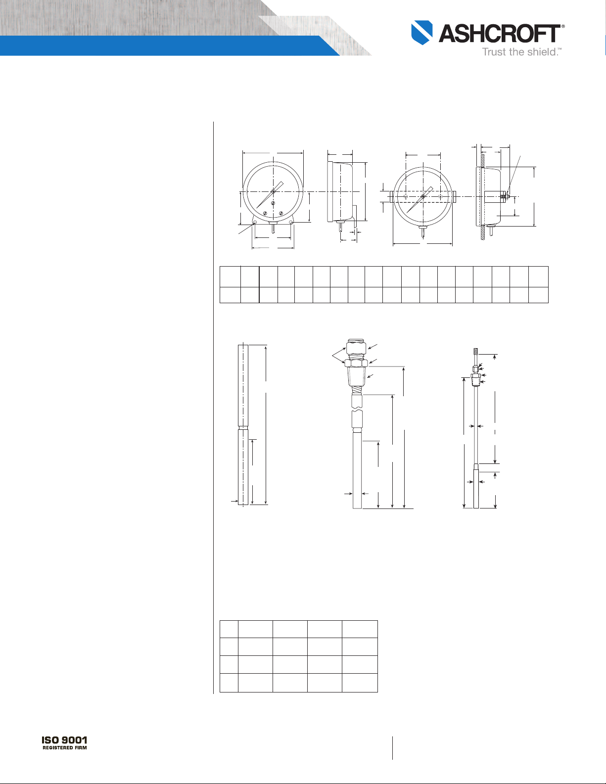
HH
2-E Dia.
Holes
D
J
B
JJ
C
AA
A
V
SURFACE MOUNTING
C
F
F
F
H
H
M
D
ia. hole
i
n panel
S
F
LUSH PANEL MOUNTING
CC
EE
DD
7/16 Hex (11)
Adjustable Union Connector
5/8 Wrench Flats (16)
1/2 NPT
15/16 (24) Clearance Hole
3/16 (4,7) Dia.
B
endable Extension
A
B
S
3/8 (10) Dia.
Sensitive Portion
13-1/4˝
(336)
3˝
(66)
Sensitive
P
ortion
3
/8˝ Dia.
(
10)
S
13/16 Hex (21)
7/8 Hex (22)
1
/2˝ NPT
1-1/16˝ (27)
Dia.
C
learance
H
ole
M
in. 7-1/4˝
(
184)
Max. Line
Length
7-1/4˝
(184)
3
˝
(76)
Sensitive
P
ortion
3/8˝ Dia.
(10)
A
djustable
Union
Connection
on Armor
Case Dimensions
Dial
Size A B C D E F J M S U AA CC DD FF EE HH JJ
nches
I
423⁄32 23⁄16 51⁄8 11⁄16 7⁄32 15⁄8 1⁄16 425⁄32 7⁄16 17⁄16 25⁄8
1
4
⁄2
(120) (56) (130) (27) (6) (141) (2) (121) (11) (37) (67) (25) (57) (41) (76) (89)
NOTE: Dimensions in inches, ( ) are millimeters.
10-24
Bulb Style and Armor Dimensions
1 2
1
⁄4 15⁄8 3 31⁄2
BULLETIN DT 600A-01
Style B03
13˝ plain bulb for applications
used in open tanks where pressures and velocities are negligible.
Armor Style A1
AISI 302 stainless steel spring
armor is supplied as standard.
Originally designed for U.S. Navy
Hi Shock thermometers
Style B08
The compression fitting fastens
anywhere along the armored line.
This bulb style is well suited for
insertion requirements in excess of
131⁄2˝. The B08 style is not a pressure tight connection. A thermowell is recommended for this style
and for all bulb styles.
Style B01, B17 & B18
Are bendable extensions with union
connections. B01 (12˝ bendable
extension) is the standard
Duratemp bulb style and is suitable
for a variety of insertion lengths
and lagging requirements. B17 is a
18˝ bendable extension, B18 is a
24˝ bendable extension. The union
connection on all three styles is
pressure tight and can be freely
moved the entire length of the
Bulb Bulb “S” “S”
Code Size “B” “A” Max. Min.
3 12 15 4
B01
(76) (305) (381) (102)
3 18 21 4
B17
(76) (457) (533) (102)
3 24 27 4
B18
(76) (610) (686) (102)
All specifications are subje ct to change without notice.
All sales subject to standard terms and conditions.
© 2014 Ashcroft Inc. 07/14
Ashcroft Inc., 250 East Main Street, Stratfo rd, CT 06614 USA
Tel: 203-378-8281 • Fax: 203-385-0408
email: info@ashcroft.com • www.ashcroft.com
bendable portion. After installation,
the bendable extension may be
formed to suit the application.
 Loading...