

Page 1
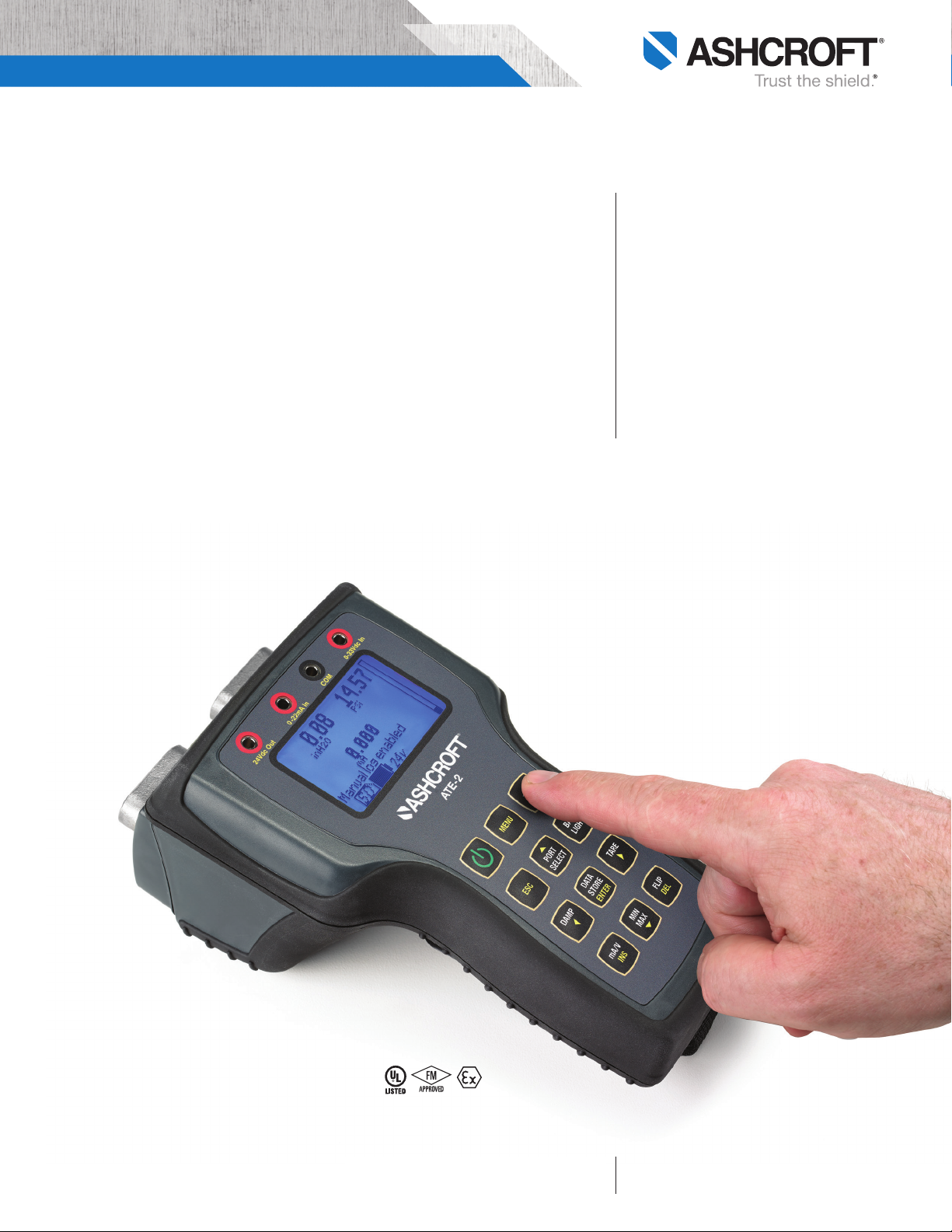
ATE-2 Handheld Calibrator
STANDARD BASE UNIT
FEATURES
• Data logging
• IP65 / NEMA 4X enclosure
• Onboard 24Vdc loop power supply
(non-intrinsically safe version)
• Optional intrinsically safe approvals
(FM, ATEX, CSA)
• SD memory card slot
• USB interface
• 13 Engineering units of measure
• Large back lit display
• 180 Degree flip display
• Programmable damping
• Switch test function
• Percent error function
• Min/max recall
• Push-button zero adjust
• Tare function
• Hot swap capability
The Ashcroft ATE-2 calibrator is
designed to measure pressure, temperature, voltage or current. It includes the
capability to display up to two modules
and one electrical measurement simultaneously, along with logging data to internal memory or communicating directly to
a PC via USB connection.
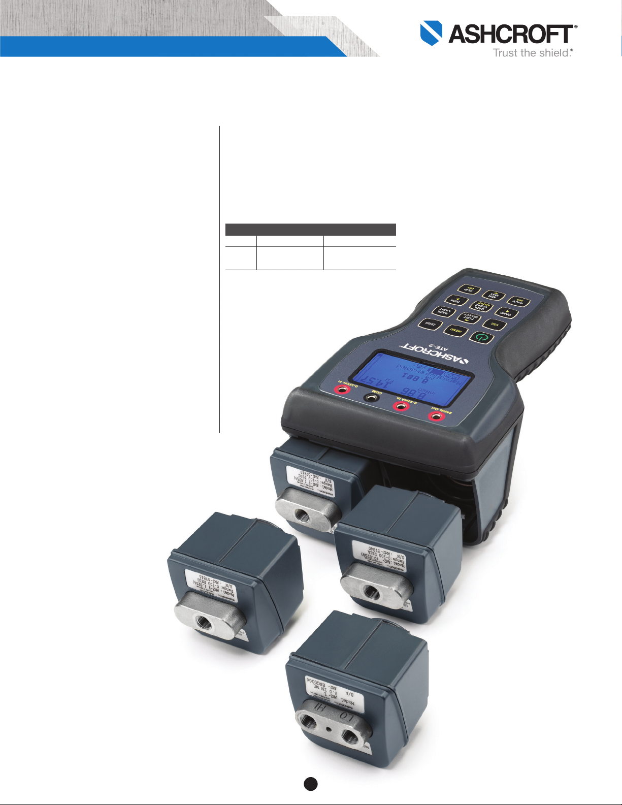
The ATE-2 has a wide selection of pressure modules, covering ranges from 0.25
inches H20 through 10,000 psi. The base
unit design allows the user to operate
one or two modules. Modules are interchangeable, and can be changed without
the need of tools, minimizing downtime.
The ATE-2 provides a large LCD
display for ease of reading measurements
and configuring the calibrator.
The unique product platform also
includes data logging; with internal
storage capacity for up to 16,000 records
on up to 64 data log files that can be
transferred to an SD card.
A wide range of approvals including UL,
FM, ATEX and CSA make the ATE-2
a popular choice worldwide.
large, bright
LOOK FOR THESE MARKS ON
OUR PRODUCTS
display for ease
of use
All specifications are subject to change without notice.
All sales subject to standard terms and conditions.
© Ashcroft Inc. 2018 ate-2_calibrator_ds1.0, Rev. A, 09/18
Ashcroft Inc., 250 East Main Street, Stratford, CT 06614 USA
Tel: 203-378-8281 • Fax: 203-385-0408
email: info@ashcroft.com • www.ashcroft .com
Page 2

ATE-2 Hand Held Calibrator
ATE-2 STANDARD FUNCTIONS
• Data logging allows the user to save
pressure, temperature and or electronic
values displayed on the LCD to internal
memory. Internal memory can hold up
to 64 data log files and a total of up
to 16,000 individual records. Manual
logging is initiated with a single key
press. Automatic data logging can be
programmed to collect data at timed
intervals between 0.1 second and 24
hours.
• SD Memory Card Slot gives the ATE-2
additional data storage capability limited
only by the capacity of the SD card
installed. Data logs stored on the SD
card are saved in .csv format which
can be read by most spreadsheet
programs. Data can easily be transferred from the ATE-2 to a PC.
• Loop Power Supply is a standard
feature on non-I.S. units, and allows the
user to conveniently power the device
under test with 24Vdc up to 35mA.
• Percent Error Function can be used
when calibrating pressure transducers.
Calculations are performed by the
ATE-2 eliminating potential for human
errors. This function enables the user
to program the full scale range and
electrical output of the transducer
under test and will display the actual
pressure and electrical output readings
as well as a percentage value comparing the actual output to the theoretical
output.
• Switch Test Function allows the oper-
ator to calibrate and document the
pressure switch function. The on-board
display will show pressure switch trip
point, reset point and will calculate
switch deadband. All calculations are
performed by the ATE-2 eliminating
potential for human errors.
• Dual Mode Function allows the oper-
ator to add or subtract the measured
pressure values from two installed
Quick-Select™ pressure modules. This
allows for measurement of “high-line”
or elevated static differential pressures.
This feature also offers the ability to
add barometric pressure from an absolute pressure module to the measured
pressure from a gauge pressure module, giving the user the ability to measure a variety of absolute pressures
without using designated modules.
BASE UNIT SPECIFICATIONS
Ashcroft Model:
ATE-2
Dimensions:
8.7 in. (L) x 5.1 in. (W) x 3.8 in. (H)
Unit Weight (no modules):
2.4 lbs
Case Material:
High-impact PC-ABS
Enclosure:
IP65 / NEMA 4X
Sensor Module Capacity:
Two bays for Ashcroft AM2 sensor modules
LCD Display:
2.5˝ (W) x 1.5˝ (H); displays three (3) simultaneous
measurements, bar graph, back light and
flip-screen capability
Electrical Connection:
4mm banana jacks – 1 set of test leads included
with each ATE-2
Loop Power Supply:
24Vdc-35mA maximum (non I.S. only)
Available Engineering Units:
psi, in.H2O, in.Hg, ftSW, bar, mbar, kPa,
MPa, mmHg, cmH2O, mmH2O, kg/cm2,
User Programmable
Operating Temperature Range:
–4 to 120°F (–20 to 49°C)
Storage Temperature:
–4 to 158°F (–20 to 70°C)
Update Rate:
100ms – 1 module installed
200ms – 2 modules installed
300ms – 2 modules installed and external input
Resolution:
±0.001% span; 99,999 counts
Warm-Up Time:
5 minutes for rated accuracy
Electrical Measurements:
0-20mA or 0-30Vdc
Input Volts Accuracy
0/10 Vdc ±0.025% fs
10/30 Vdc ±0.10% fs
0-20mA ±0.03% fs
2
Page 3
ATE-2 Handheld Calibrator
Programable Filtering (Damping):
Levels 1 through 16
Temperature Effect Electrical Measurement:
±0.001% of span per F over compensated range
from reference temperature of 70°F (±3°F)
Serial Interface:
USB (Micro-B connector type)
Field Calibration: Base Unit and pressure
modules may be field-calibrated via keypad
commands
Data Logging:
• Internal storage for up to 64 data logs and up to
16,000 records; transferrable to SD card
• Manual / automatic data logging capability
•
Programmable data intervals (0.1 sec. to 24 hrs.)
Agency Approvals:
CE Mark, FCC (CFR47), UL 61010-1
OPTIONAL FEATURES
Hazardous Location Version
(Battery Powered Only):
FM Intrinsic Safety CL 1,
Div 1, Gr A, B, C, D
CSA Intrinsic Safety CL 1,
Div 1, Gr A, B, C, D
ATEX Ex ia ii c T4 Ga –20°C<Ta<+50°C
Note: Loop power supply is not included with
Intrinsically Safe Units
Power Requirements:
(4) AA Batteries or via USB power supply
USB universal AC adapter 100-240Vac, 50/60 Hz
Battery Life:
Up to 40 hours battery with 2 modules installed
Certification:
N.I.S.T. traceable certification document provided for
base unit and Quick-Select sensor modules.
HOW TO ORDER ATE-2 BASE UNIT
P/N Description Version
ATE2ST Ashcroft Base Unit (ST) Standard
ATE2IS Ashcroft Base Unit (IS) Intrinsically Safe
a large variety
of pressure and
temperature
modules are
available
3
Page 4

ATE-2 Hand Held Calibrator
OPTIONAL PRESSURE
MODULE FEATURES
• AM2-1 Low Pressure Module
• AM2-2 Medium/High Pressure
Module
• Hot Swap
• Accuracies from 0.025% to 0.1%
• Low Pressure Ranges from ±0.25
InH2O to 200 InH2O
• Medium/High Pressure Ranges
from 5 psi up to 10,000 psi
• Gauge, Absolute, Differential,
Vacuum and Compound Ranges
Quick-Select™ Pressure Modules
Available in full-scale ranges from
0.25 inches H20 through 10,000 psi.
Gauge, vacuum, absolute, differential or
compound pressure ranges are available.
Select from multiple modules that can
be quickly interchanged (“hot-swapped”)
without the use of tools, and are automatically recognized once installed in the
base unit.
Ashcroft Low Pressure Module AM2-1
The AM2-1 Quick-Select low pressure
module is based on a proprietary, variable-capacitance sensor. This sensor is
available in ranges from 0.25 to 0/200
inches H20 with accuracies from ±0.1%
to ±0.06% of span, and are available for
gauge, differential and compound pressures. They are suitable for use with dry,
non-corrosive gases
The variable-capacitance sensing
element incorporates a micro-machined
silicon diaphragm. Silicon provides optimum repeatability with minimal hysteresis.
The sensor is extremely stable, due to the
sputtered metal capacitance plates being
molecularly bonded to the silicon. This
design eliminates adhesives from the sensor assembly.
The AM2-1 sensor is also extremely
rugged. It can withstand extreme overpressure, shock and vibration without significant error or calibration offset.
Ashcroft Medium / High Pressure
Module AM2-2
The AM2-2 Quick-Select pressure
module incorporates a piezoresistive,
micro-machined silicon sensor. These
sensors are available in ranges from 5 psi
through 0-10,000 psi, and are also offered
in absolute, vacuum and compound
ranges with accuracies from 0.025% to
0.1% of span. 316 SS sensor isolation is
provided on all ranges except for 10,000
psi which is 17-4 PH stainless steel, and
is suitable for applications involving fluids
or corrosive gases.
Optional enhanced accuracy eliminates
temperature error over the entire compensated temperature range of high pressure
modules.
OPTIONAL PRESSURE SENSOR
MODULE SPECIFICATIONS
AM2-1 LOW PRESSURE MODULE
Pressure Types:
Gauge, differential and compound
Available Ranges:
Refer to Range Table
Available Accuracies:
±0.06 (0/1-0/200˝ in.H20),
±0.07 (0/0.25-0/0.5˝ in.H20), or 0.1% of Span
Compensated Temperature Range:
20 to 120°F (–7 to 49°C)
Temperature Effect:
±0.004% of Span per °F over compensated
range from reference temperature range of
70°F (±3 degrees)
Repeatability:
±0.01% of Span (range 0/1 in.H20 or higher)
±0.02% of Span (range below 1.0 in.H20)
Sensitivity:
±0.002% of Span (typical)
Media Compatibility:
Clean, dry, non-conductive, non-corrosive gas
Under / Overpressure Capability:
–15 to 50 psi
Maximum Static (line) Pressure:
100 psi
Process Connection:
Standard 1⁄8 NPT Female
Agency Approvals:
FCC (CFR47), UL-61010-1
Not RoHS compliant
4
Page 5

ATE-2 Handheld Calibrator
AM2-2 MEDIUM/HIGH PRESSURE MODULE
Pressure Types:
Gauge, absolute, compound and vacuum
Available Ranges:
Refer to Range Table
Available Accuracies:
±0.025%, 0.05% or 0.1% of Span (10,000 psi
only offered in psig and 0.1% accuracy)
Compensated Temperature Range:
20 to 120°F (–7 to 49°C)
Temperature Effect:
Standard:
±0.004% of Span per °F over compensated range
from reference temperature range of 70°F (±3
degrees)
Optional:
Enhanced Accuracy Option.
No additional error due to ambient temperature
from +20°F to +120°F
Sensitivity:
±0.002% of Span (typical), ±0.001 span (max)
Repeatability:
±0.01% of Span
Media Compatibility:
Any medium compatible with 316 SS isolation;
10,000 psi range only available with
17-4 PH / 316 SS
Optional:
Cleaned to meet ASME B40-100 Level IV.
NOT marked for oxygen service.
Overpressure Compatibility:
200% for ranges to 1000 psi
150% for ranges > 1000 psi
Agency Approvals:
CE, FCC (CFR47), UL-61010-1
Process Connection:
Standard: 1⁄8 Female NPT
Optional: 1⁄8 Female NPT with Flush Port
Optional: Welded VCR Fitting with
Standard Finish (up to 5000 psi)
HOW TO ORDER PRESSURE MODULES
Refer to Product Ordering Table on Pages 6 and 7
hot-swap
modules
without
the use
of tools
5
Page 6

O INLET FITTING
2
O mmH
2
DIFFERENTIAL PRESSURE RANGES
O mmHG kPa mbar cmH
2
InH
O 0.25 0.5 0.2 0.6 0.6 6 A - 1/8 NPT INTERNAL
PRESSURE
UNITS
2
mBar 2 3 2.5 4 5 50
ATE-2 Hand Held Calibrator
1 1.5 15
0.4
(All prefixed by +/– sign)
COMPOUND PRESSURE RANGES
1 2 0.6 2.5 3 30
0.5 1
0.25 0.5 0.25 0.6 0.6 6
1.5 3 1 4 5 50
O 3 5 4 6 6 60
2
cmH
O 5 10 6 10 15 150
2
mmH
10 20 10 25 30 300
15 30 25 40 60 600
25 50 40 60 150 1500
50 100 100 200 2000
100 200 250 500 5000
150 300 400
200 500
0.125 0.2 0.1 0.25 0.3 3
point will be designated with a letter “P”. For
example 0.5 code is P5
Note: Pressure range codes which contain a decimal
A
200
O (shaded values).
5 10 2.5 10 15 150
2.5 5 1.6 6 6 60
7.5 15 6 16 20 200
12.5 20 10 25 30 300
25 50 25 60 60 600
50 75 100 150 1500
75 100 160 200 2000
100 150 250 300 3000
2
O and higher.
2
Pressure Range Inlet Fitting
1 0 0
TYPE
PRESSURE
MEDIA
COMPATABILITY
C - .06% STD. ACCURACY D - DIFFERENTIAL mmHG 0.5 1 0.5 1 1.5 15
C - .07% STD. ACCURACY kPa 1 2 1 2.5 3 30
PRODUCT CODE – LOW PRESSURE MODULES
AM2 1 C A D INH2O A
MODEL SENSOR TYPE ACCURACY
“C” accuracy is 0.07% for ranges below 1.0 inH
Note: “C” accuracy is 0.06% for ranges 1.0 inH
Pressure Units
I N H 2 O
D
Pressure Type
A
Media
Compatability
C
1
Sensor Type Accuracy
Model
A M 2
Product Code Example:
AM2- ASHCROFT MODULE 1 - CAPACITIVE SENSOR B - .1% STD. ACCURACY A - NON-ISOLATED SENSOR C - COMPOUND InH
6
Page 7

O INLET FITTING
2
*
= Gauge pressure only (no absolute)
2
Mpa mmH
2
BAR
kgcm
O mmHG
2
THREAD
A - 1/8 NPT INTERNAL
B - 1/8 NPT INTERNAL
WITH FLUSH PORT
C - G 1/8 BRITISH STD
D - G 1/8 BRITISH STD
WITH FLUSH PORT
*3000
250 1 1
500 1.6 1.6 5000
*300 *300
THREAD MS33649-02
E - 0.3525-24 UNJF-3B INTERNAL
point will be designated with a letter “P”. For
example 0.5 code is P5
Note: Pressure range codes which contain a decimal
*25 *250 *250
GAUGE / ABSOLUTE PRESSURE RANGES
10
O InHG kPa mbar cmH
2
*100
psi InH
UNITS
PRESSURE
TYPE
PRESSURE
MEDIA
COMPATABILITY
O 10 150 20 40
2
A - ABSOLUTE InH
C - COMPOUND kPa 20 300 50 100 500 500 1000 4 4
W - Clean to ASME
B40-100 Level IV spec
O 50 500 200 250 1000 1000 3000 10 10
2
cmH
BAR 100 1000 500 600 2000 2000 25 25
mmHg 60 800 300 400 1600 1600 5000 16 16
mBar 30 400 100 160 600 600 1500 6 6
250 5000 5000 100
300 6000 6000 160
500 10000 10000 250
600 400
1000 500
1500
2000
2
O 200 4000 4000 60 50
2
Mpa 150 1000 2500 2500 40 40
kgcm
mmH
PRODUCT CODE – MEDIUM & HIGH PRESSURE MODULES
2500
3000
5000
6000
7500
VACUUM RANGES
10 20 60 600 600 500 0.6 5000
*10000
V400 V4
COMPOUND PRESSURE RANGES
(NOTE: All symmetric ranges prefixed with +/– sign)
-NOTE: 10,000 PSI = 0.1% ACCURACY AND GAUGE PRESSURE ONLY
5 100 10 25 300 300 300 0.25 3000
15 30 100 1000 1000 750 1
10 250 20 40 600 600 500 0.4 6000
V15 V400 V30 60 V1000 V1000 V750 0.6 V10000
V30 V60 V100 V2000 V2000 V1500 V1
V60 V100 V200 V4000 V4000 V3000 V2
A
Pressure Range Inlet Fitting
1 5 0 0
Pressure Units
P S I
G
Pressure Type
B - .1% STD. ACCURACY I - ISOLATED SENSOR G - GAUGE psi 5
C - .05% STD. ACCURACY
D - .025% STD. ACCURACY V - VACUUM InHG 15 250 30 60 400 400 750 2.5 2.5 10000
SENSOR
2 - PIEZ0-RESISTIVE
AM2 2 H I G PSI A
MODEL SENSOR TYPE ACCURACY
AM2- ASHCROFT MODULE
ACCURACY
ACCURACY
ACCURACY
F - .1% ENHANCED.
G - .05% ENHANCED.
H - .025% ENHANCED.
I
Media
Compatability
H
Sensor Type Accuracy
Model
A M 2
Product Code Example:
7
Page 8

ATE-2 Hand Held Calibrator
OPTIONAL TEMPERATURE
MODULE FEATURES
• Measures temperature with
most RTD probes
• Supports 2, 3 & 4-wire RTDs
• Displays measurement for Fahrenheit,
Celsius, Kelvin, Rankine and ohms
• Easy configurability to meet
application requirements
The Ashcroft ATE-2 provides accurate temperature measurement when using the AM2-RT module
with an RTD probe. This system supports the most
common RTD’s without requiring operator input of
probe characterization data; each module comes
factory-programmed with standard curves for
Pt100 (385 & 392), Ni 120, Cu 10 and temperature
probes.
The setup menu allows the operator to choose
configurations for 2, 3 or 4 wire RTD probes and
decimal resolution. The temperature measurement
system includes the ability to automatically track
minimum / maximum values.
RTD TEMPERATURE MODULE SPECIFICATIONS:
Following specification is based on use of 4 wire
RTD probe; accuracy does not include contribution
from RTD
Part Number:
AM2-RT1, AM2-RT2
AM2-RT1 MODULE
Used with RTD Measurement Range
Probe Type and Accuracy
Pt100 (385 –200 to 550°C: ±0.15°C 0.01°C or F
& 392) 550 to 850°C: ±0.2°C
Ni 120 –80 to 260°C: ±0.1°C 0.1°C or F
Cu 10 –70 to 150°C: ±0.6°C 0.1°C or F
Ohms ±0.01% reading ±0.02 ohms 0.004 ohms
Resolution*
AM2-RT2 MODULE
Used with RTD Measurement Range
Probe Type and Accuracy
Pt1000 –200 to 550°C: ±0.15°C 0.01°C or F
Ohms ±0.01% reading ±0.02 ohms 0.004 ohms
* Select from 1, 0.1, 0.01 and 0.001 degrees or ohms. Resolution for a
given probe is dependent on the output of the probe. Maximum resolution
is 1 part in 100,000 of full scale ohms Select from 1, 0.1, 0.01 and 0.001
degrees or output for the probe.
Temperature Error:
Better than ±0.0005% of
Resolution*
reading per degree Fahrenheit from a reference
temperature of 70° ±3° degrees F°
Input Receptacle: TA4F type RTD connector
HOW TO ORDER RTD PROBES FOR USE WITH
AM2-RT1 MODULE
Probes are all 4 wire RTD’s with 304 stainless
steel sheath an a installed TA4F electrical connector for compatibility with AM2-RT1 interface
modules. They are provided in DIN Class A
accuracy.
HOW TO ORDER RTD PROBES
Part No. Description
840X010-01 Pt100 (385), 0.125 diameter,
12 inch length, handle and 5 ft.
coiled cable
840X010-02 Pt100 (385), 0.25 diameter, 12
inch length, handle and 5 ft.
coiled cable
840X010-05 Pt100 (385), 0.125 diameter,
6 inch length, handle and 5 ft.
coiled cable
840X010-06 Pt100 (385), 0.25 diameter, 6
inch length, handle and 5 ft.
coiled cable
840X010-11 Pt100 (385), 0.125 diameter,
8 inch length, handle and 5 ft.
coiled cable
840X010-03 Pt100 (385), 0.125 diameter, 12
inch length, 10 ft. straight extension lead with plug (no handle)
840X010-04 Pt100 (385), 0.25 diameter, 12
inch length, 10 ft. straight extension lead with plug (no handle)
840X010-07 Pt100 (385), 0.125 diameter, 6
inch length, 10 ft. straight extension lead with plug (no handle)
840X010-08 Pt100 (385), 0.25 diameter, 6
inch length, 10 ft. straight extension lead with plug (no handle)
828X136-01 TA4F mating connector for use
with AM2-RT1 module and user
supplied RTD probe
8
Page 9

ATE-2 Handheld Calibrator
AM2-TC1 QUICK-SELECT
OPTIONAL THERMOCOUPLE
MODULE FEATURES
• Allows ATE-2 to measure tempera-
ture with a thermocouple
• Pre-programmed to accept 8 most
common thermocouple types
• Selectable units of measure: Celsius,
Fahrenheit, Kelvin, Rankine and
millivolts
• Reference junctions: automatic
internal or manual external
With the AM2-TC1 interface module installed, the
ATE-2 contains programming to read types J, K,
T, E, R, S, B and N thermocouples and display the
measurement in units of temperature measure or
millivolts. Other types of thermocouples may also be
read by using the direct millivolt readout.
THERMOCOUPLE TEMPERATURE MODULE
SPECIFICATIONS
Part Number:
AM2-TC1
Unit of Measure (selectable): °C, °F, °K,° R and
millivolts
Reference Junction (selectable):
Automatic Mode: The AM2-TC1 module incorpo-
rates an internal resistor/thermistor based reference
junction, which may be selected for use in the temperature readout mode.
Manual Mode: An external reference junction may
be used in place of the internal junction. External reference junctions may be applied in the temperature
or direct millivolt readout modes.
Resolution Reading in Temperature Units
(selectable):
1, .1 or .01 degrees. “Auto” mode selection that
allows the ATE-2 to automatically configure the readout to the highest significant resolution
(resolution closest to the tolerance) for the thermocouple type selected.
Resolution Reading in Millivolts:
.001 millivolts
Thermocouple Connection
(to interface module):
Requires a “miniature thermocouple connector”
(Omega type SMP), specifically matched to the thermocouple type to be used. These connectors may be
purchased as an accessory under the following part
numbers:
HOW TO ORDER THERMOCOUPLE CONNECTOR
Part No. Description
828X161-01 Type J Connector
828X161-02 Type K Connector
828X161-03 Type T Connector
828X161-04 Type E Connector
828X161-05 Type R Connector
828X161-06 Type S Connector
828X161-07 Type B Connector
828X161-08 Type N Connector
SYSTEM ACCURACY (READING IN
TEMPERATURE UNITS):
Includes the base unit and AM2-TC1 interface
module. (Does not include inaccuracy of the
thermocouple device. Consult thermocouple
manufacturer or ANSI MC96.1 for thermocouple
accuracy specifications. Typical inaccuracies
range from ±1 to ±2.2°C.)
Conversion Factors to convert °C
specifications to other units of measure:
To convert from C to F; F = (1.8 x C) + 32
To convert from C to K: K = C + 273.15
To convert from C to R; R = (1.8 x C) + 427.67
Additional Thermocouple Information on the
following page.
9
Page 10

ATE-2 Hand Held Calibrator
THERMOCOUPLE SPECIFICATION TABLE
Accuracy @ 25°C
(Not Including Internal
Reference Junction)
Expressed as ±°C
0.7
0.3
1.5
1.0
0.5
1.5
0.8
0.5
1.2
0.6
0.3
3.4
1.2
14.0
5.0
3.0
1.2
4.3
2.1
1.0
Thermocouple Type
J
K
T
E
R & S
B
N
Measurement Range
(°C)
-210 to -151
-150 to 1200
-240 to -201
-200 to -101
-100 to 999
-250 to -201
-200 to -101
-100 to 400
-250 to -201
-200 to -101
-100 to 400
-50 to 299
300 to 1768
100 to 199
200 to 499
500 to 999
1000 to 1820
-250 to -226
-225 to -101
-100 to 1300
Accuracy @ 25°C
(Including Internal
Reference Junction)
Expressed as ±°C
1.1
0.4
2.2
1.5
0.8
2.2
1.2
0.8
2.0
1.1
0.6
3.6
1.3
14.0
5.0
3.0
1.2
5.7
2.8
1.4
Max Additional Error Due
to Ambient Temperature
Deviation From 25°C.
Expressed as Additional °C
Deviation from 25°C
0.02
0.01
0.05
0.03
0.02
0.05
0.03
0.02
0.04
0.02
0.01
0.10
0.04
0.44
0.16
0.08
0.04
0.14
0.07
0.02
AMBIENT TEMPERATURE EFFECT:
To calculate, multiply degrees deviation from
25°C times the value listed in the far right column
of the listed table. Only applied when using the
internal reference junction, within the ambient
window of 0-50°C.
TO CALCULATE TOTAL SYSTEM/MEASUREMENT
ACCURACY:
Accuracy = System Accuracy @ 25°C + System
Ambient Temperature Effect + Inaccuracy of
Thermocouple Device
SYSTEM ACCURACY (BASED ON DIRECT
MILLIVOLT READING FROM THERMOCOUPLE):
Includes the base unit and AM2-TC1 interface
module. (Does not include inaccuracy due to the
thermocouple device. Reference junction not
applicable to direct millivolt readings.)
Max. Additional Error Due
Input
Range of
Module
10 to
100mV
Accuracy
@ 25°C
±0.01 to
100mV
to Ambient Temperature
Deviation From 25°C.
Expressed As Additional
Millivolt Error Per Each °C
Deviation From 25°C
.001
10
Page 11

ATE-2 Handheld Calibrator
OPTIONS
Carrying, Transport and Protective Cases:
Contoured: Protective Instrument Case with
Shoulder Strap. P/N 864D079-01
DIMENSIONS
Base Unit
5.06
ATE-2
3.59
8.05
3.80
8.56
Heavy Duty, Watertight Instrument Carrying /
Transport Case. P/N ATE2-CASE
Carrying Case
18 3/8˝
(REF. )
3
19
(REF.)
/8˝
8˝
(REF.)
1
14
(REF. )
/4˝
11
 Loading...