

Page 1

ASHCROFT ATE-2
Operation and
Maintenance Manual
0.054
PS I
0.86
in H 20
All specifications are subject to change without notice.
All sales subject to standard terms and conditions.
© 2014 Ashcroft Inc., 1P 07/14 I&M002-10233
I
Page 2

II
Page 3

Congratulations on your purchase of a Ashcroft ATE-2, one of
the finest precision pressure measuring instruments available
anywhere. These instruments are precision devices, designed to
measure, indicate pressure, temperature, DC voltage or current
with an extremely high degree of accuracy and are rugged
enough to provide laboratory performance in field service. All
parts have been designed and selected for such service and with
proper care and maintenance this instrument will perform within
specifications for years of trouble free service.
TABLE OF CONTENTS SECTION TOPIC PAGE
Section 1. Warnings ...................................................................................................................3
Section 2. Introduction ..................................................................................................................7
Section 3. Specifications ...............................................................................................................8
Section 4. Base Unit Overview ...................................................................................................10
Section 5. How To Obtain Programming Pass Codes ................................................................. 11
Section 6. Module Overview .......................................................................................................11
Section 7. Unpacking .................................................................................................................14
Section 8. Storage .................................................................................................................14
Section 9. Cleaning .................................................................................................................14
Section 10. Battery Installation ..................................................................................................... 14
Section 11. Module Installation ..................................................................................................... 15
Section 12. Startup Basic Function ..............................................................................................15
Section 13. Key Function Overview .............................................................................................. 17
Section 14. Measurement Mode Functions
a. ESC ................................................................................................................. 18
b. Port Select ...........................................................................................................18
c. Data Storage ........................................................................................................18
d. Zero ................................................................................................................. 18
e. Back Light ............................................................................................................18
f. Damping .............................................................................................................19
g. Manual Datalogging ............................................................................................. 19
h. Tare ................................................................................................................. 20
i. mA/V Monitoring ..................................................................................................22
j. Wiring Diagrams ..................................................................................................22
k. 24VDC Power Supply Enable/Disable .................................................................23
l. Min/Max Function ................................................................................................24
Section 15. MENU Mode Functions and Programming ................................................................ 25
a. MENU Mode General Key Functions ...................................................................25
b. Base Unit Set Up .................................................................................................26
i. Programming Date and Time ......................................................................... 26
ii. Programming Owner Name ........................................................................... 27
iii. Program Auto Off and Back Light Timers ......................................................27
c. Engineering Units Selections ...............................................................................28
d. H2O Temperature Conversion Selection ..............................................................29
e. Programing User Defined Unit of Measure .......................................................... 29
f. Datalogging Setup ...............................................................................................30
i. Set Channel Tag Names ................................................................................31
ii. Program Auto Datalog Time ...........................................................................31
iii. Initiate Auto Datalogging ................................................................................32
iv. Initiate Manual Datalog .................................................................................. 32
v. Review Datalog Data .....................................................................................33
vi Export Data to SD Card .................................................................................35
vii. Clear Internal Memory Storage .....................................................................35
1
Page 4

TABLE OF CONTENTS (cont.)
g. Switch Test ........................................................................................................... 35
h. Percent (%) Error Function ..................................................................................37
i. Dual Mode Functions ...........................................................................................41
j. RTD Temperature Measurement ..........................................................................42
k. Thermocouple Temperature Measurement ..........................................................45
l. Firmware Update .................................................................................................47
m. Communications Interface ................................................................................... 55
i. USB Cable Installation ...................................................................................55
ii. Driver Installation ...........................................................................................56
iii. Terminal Set Up ............................................................................................. 58
iv. Inquiry Mode ..................................................................................................59
v. Jour nal Mode .................................................................................................60
vi. ISO 1745 Mode .............................................................................................. 60
n. Calibrate Base Unit ..............................................................................................60
o. Pressure Module Calibration ...............................................................................66
Section 16. Appendices
A. Conversion Factor Table ................................................................................71
B. Trouble Shooting and Error Codes ................................................................72
C. ISO Commands .............................................................................................77
D. RTD Probe Connections, TC External Reference Connection ......................79
E. System Accuracy With Thermocouple Interface ............................................ 80
F. Approved SD Data Cards ..............................................................................80
2
Page 5

ASHCROFT ATE-2 GENERAL INFORMATION
The information in this manual pertains to Ashcroft ATE-2 Hand
Held Calibrators; referred to as the HHC or ATE-2. This manual
also covers sensing modules used with the HHC; referred to as
AM2 modules.
This manual provides the following information:
• Precautions, Warnings and Safety Instructions
• Product Specifications
• Basic Maintenance
• Verification and Test Procedures
• Programming Instructions
• Calibration and Adjustment Procedures
• Accessories and Replaceable Parts
The ATE-2 is intended to perform the following functions
• Display one or two high accuracy pressure and/or temperature measurements
• Display one DC voltage or current value
• Record datalogs of the displayed measurements (up to
16,000 records on internal memory organized in up to 64
datalogs)
• Transfer datalogs to an onboard SD memory card
• Communicate directly to a PC via USB connection
• Allow for accurate measurement of various pressure and
temperature ranges by use of interchangeable Quick-Select
modules
• Allow for field recalibration of base unit and pressure
modules.
• Provide power to devices from an internal 24Vdc loop supply
(non-I.S. only)
TERMS IN THIS MANUAL
WARRANTY INFORMATION
SECTION 1.0 WARNINGS
WHEN YOU SEE THESE SYMBOLS
Terms used in this manual
• HHC or Base Unit refers to the Model ATE-2 Hand held Calibrator Base Unit
• Capacitive Module refers to Model AM2-1 low pressure
sensor module
• Piezo Module or Piezoresistive Module refers to Model
AM2-2 high pressure sensor module ( Note the 10K psi
range, only, uses a Polysilicon thin film sensor)
• Quick-Select Module refers to any pressure or temperature
module model noted above
All Ashcroft Products and Parts carry a warranty against defective material or workmanship for a period of one (1) year from the
date of shipment. (See complete policy, page 81.)
Information provided in this document is for the use of qualified
personnel only. Do not perform tests or calibrations described in
this manual unless you are qualified to do so.
Use the ATE-2 calibrator only as described in the user manual,
supplements and appendices.
IMPORTANT APPLICATION INFORMATION
IMPORTANT SAFETY INFORMATION
3
Page 6

PURPOSE AND SCOPE
OF MANUAL
SAFETY PRECAUTIONS:
IMPORTANT
Please read the entire manual thoroughly before using the instrument or attempting any service or repair work. The instructions in
this manual are intended to be performed by qualified instrumentation or technical personnel only. This manual should be kept
with the instrument or in a place of safe keeping at all times, as
it contains pertinent information for operation and maintenance.
Additional manuals can be ordered through Customer Service. If
additional assistance is needed, contact our Customer Service
Staff at:
Ashcroft Inc.
250 East Main Street
Stratford, CT 06614-5145, USA
Tel: 203-378-8281
Fax: 203-385-0402
email: info@ashcroft.com
Please be sure to include instrument model number and serial
number in all correspondence to assure proper identification.
Ashcroft Inc. does not recommend trouble-shooting or repairs
beyond the scope of this manual. Problems which cannot be
remedied by following the instructions in this manual should be
referred to the manufacturer. Immediate assistance can often be
supplied by telephone. Defective components will be repaired or
replaced by the manufacturer at his discretion. Repaired products
will be returned to the user by the same mode of shipment. Airmail and air express is recommended for urgent shipments.
Electronic pressure instruments must be selected in accordance
with industry codes and safety practices to avoid the possibility of
misuse or misapplication which could result in personal injury or
property damage. Personnel responsible for selection and installation should also be familiar with the safety recommendations of
ASME B40.1, that apply to elastic pressure elements and their
application in general and specific services. ANSI B40.1 is available from:
ASME
345 East 47th Street
New York, NY 10017
Pressure – Select a range so that the maximum applied pres-
Vibration – Excessive vibration could cause loosening of
Pulsation – Excessive pressure pulsation could result in fatigue
Temperature – Operation of the instrument in an environment
Process – Pressure boundary materials must be resistant to
Hazardous Location – Only approved explosion proof or intrin-
Electro-Magnetic Interference – Instruments should not be used
in locations where EMI/RFI conditions exceed
sure will never exceed the upper range limit.
components resulting in loss of instrument accuracy
or failure to provide valid data.
failure of the pressure element.
where temperatures are in excess of design ratings
may result in loss of accuracy and failure.
the process media. Failure to assure compatibility
may result in pressure sensing element deterioration
or failure. Instruments used on high pressure gas,
or potentially hazardous service, such as oxygen
should be carefully selected in accordance with the
recommendations of ANSI B40.1.
sically safe instruments should be used in hazardous locations.
design ratings, to avoid erroneous performance.
4
Page 7

WARNINGS CONT.
ADDITIONAL WARNINGS
Warning to avoid shock or personal injury
• Follow all applicable equipment safety procedures.
• Inspect the calibrator before use. Do not use the calibrator if
it appears damaged.
• Close battery door and secure with lock screw before using
the calibrator.
• Check all test leads for continuity, damaged insulation or
exposed metal. Replace any damaged leads.
• Use the proper terminals, mode and range for any measuring and sourcing application.
• Connect the common lead before connecting the live test
leads.
• To prevent damage to the unit under test, be sure that the
calibrator is in the correct mode before connecting leads.
• Never apply more than 33 volts between input terminals or
between any terminal and ground.
• When using probes keep fingers away from probe contacts.
• Do not allow water or other liquids inside the calibrator case.
• Do not operate the calibrator near explosive gas or vapor
unless the calibrator is marked as approved for hazardous
area service.
• Never open the ATE-2. There are no field serviceable
components. This will void the warranty.
• When measuring pressure, be sure that the process pressure line is shut off and depressurized before connecting or
disconnecting a pressure module.
• Always use proper tools to avoid damage to pressure
measurement modules. Use a wrench to hold the module
manifold, and a second tool to tighten the mating fitting. See
drawing figure in section 12.
• Replace batteries only with approved AA alkaline batteries
(Quantity 4). Never mix new and used batteries in the calibrator.
Warnings for Intrinsically Safe approved versions only
(Refer to Supplement I.S. Manual I&M002-10212)
• When marked as approved the ATE-2 calibrator is agency
approved for use in areas when potentially flammable or
explosive gas or vapor may occur. These areas are referred
to as hazardous (classified) locations in the United States,
as hazardous locations in Canada, as potentially explosive
atmospheres in Europe and as explosive gas atmospheres
in other parts of the world. The HHC’s voltage and current
input jacks have entity parameters and as such can be utilized in a hazardous location to connect to other apparatus
as long as said apparatus meets the requirements of the
entity parameters.
• When marked with the following Symbols the calibrator is
approved by Factory Mutual (FM) for use in Class 1 Division
1, Groups A,B, C,D hazardous areas, by ATEX for use in Ex
ia ll C T4 Ga -20C<Ta<+50C and by CSA for use in Class 1,
Division 1, Groups A, B, C, D
5
Page 8
ADDITIONAL WARNINGS CONT.
250 EAST MAIN ST.
STRATFORD, CT 06614
www.ashcroft.com
INTRINSICALLY SAFE/SÈCURITÈ INTRINSÈQUE Exia
CL I, DIV 1, GR A, B, C, D. T4 -20°C≤Ta≤+50°C
II 1 G FM12ATEX0035X
Ex ia II C T4 Ga -20°C≤Ta≤+50°C
ENTITY PARAMETERS
Ui=33Vdc Ii=300mA Ci=0 Li=0 Pi=1.5W
Uo=5.735Vdc Io=586A Co=46f L0=1H Po=840W
0518
WARNING:
See Dwg #825A028 for installation, batteries
and warnings
HAND HELD CALIBRATOR 6D49 E171189
Unit contains a lithium battery. Panasonic #BR1225
is the approved replacement battery. Use of another
battery may present a risk of fire or explosion. See
owners manual for safety instructions.
Label Part# 238A746-01Rev D
• Before entering a hazardous area, close both the battery
door and USB/SD card door, and secure both with lock
screws.
• The battery access cover is not to be removed while in a
hazardous area.
• The USB/SD access door is not to be removed while in a
hazardous area.
• Replace batteries only in a non-hazardous area.
• Use only Duracell Model MN1500 AA alkaline primary cell
batteries.
• The USB connection-data transmission and power input- are
restricted to be used in a non-hazardous area only.
• The non-hazardous area USB apparatus –computer port,
wall supply, etc., connected to the USB port of the HHC,
must be assessed and conform to section 6.2.5 of EN60079-
11. This precaution is to protect the integrity of the safety
components within the HHC, which insures its intrinsic safety
rating while in the hazardous location.
• When using non- assessed USB equipment, accessory
part number 101C225-01, USB protection device, is to be
inserted between the HHC USB port and the non-assessed
apparatus.
• Do not power the calibrator by USB cable in a hazardous
area; this action will invalidate the calibrator’s intrinsic safety.
• Intrinsically safe installation diagrams, entity parameters and
warnings are included in drawing 825A028 included in the
supplemental I.S. manual.
6
Page 9
SECTION 2.0 INTRODUCTION
The ATE-2 is a simple, yet sophisticated, high accuracy, battery
or USB powered, handheld calibrator device. Used together with
interchangeable pressure and temperature modules, this device
measures, displays and can record pressure, temperature, DC
voltage or milliamp current. Up to three measurements can be
simultaneously displayed.
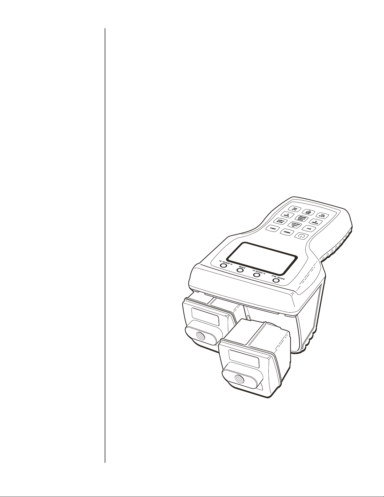
A standard system consists of a base unit and one or two
Quick-Select modules.
Quick-Select pressure modules are available in over 50 standard
pressure ranges in gauge, absolute, vacuum and compound
ranges capable of measuring pressures from 0.25 inches water
column up to 10,000 pounds per square inch.
Quick-Select temperature modules are designed to work with
several common RTD types including Pt1000, Pt100, Ni120,
Cu10, and up to six programmable resistance curves. Thermocouple temperature modules work with Types J, K, T, E, R, S, B
and N thermocouples.
in H20
0.86
PS I
0.054
7
Page 10

SECTION 3.0 PRODUCT SPECIFICATIONS
BASE UNIT PHYSICAL SPECIFICATION
Dimensions 8.7” L X 5.1” W X 3.8” H
Weight 2.4 pounds (includes two modules installed)
Case Material High Impact PC-ABS with rubberized sections
Sensor Module Capacity 2, hot swappable, modules are fully recognized automatically
Display 1.5” X 2.5” Graphic LCD Display with backlight
Power Source/Requirements 4 x AA Batteries (6.4VDC maximum) Duracell Alkaline MN1500,
or via USB port from PC or wall supply (5.25 VDC
maximum, 0.375 Amps maximum)
Real Time Clock Battery Panasonic BR1225, Lithium ion (not field replaceable)
Battery Life 50 hours with 1 module, with no back light at 70°F
40 hours with 2 modules, with no back light at 70°F
AC/DC adaptor (USB Port) USB Micro-B Connector
Electrical Connection 4mm “Banana Jack” sockets, quantity 3 or 4
Electrical Output 24 VDC output, 35mA maximum
Current Input 0-22mA
Voltage Input 0-33 VDC
Interface USB 2.0
Removable Data Storage Type SD
BASE UNIT ENVIRONMENTAL SPECIFICATION
Temperature Effect ±.004%Sp / ° F over compensated range
(+20/+120°F (-7/+50°C)
Enclosure
IP Rating (with modules) NEMA 4X / IP65, suitable for Indoor and Outdoor use
Impact / Drop Resistance IEC 60079 - 0
Warm-up time (to full accuracy) Less than 5 min.
Agency Approvals (w/modules) CE EMC Directive, IEC-61326-1: 200
FCC FCC CFR 47, Part 15, section 15.5 and 15.29
UL UL-61010-1, File # E171189
Optional Agency Approvals
(with modules)
FM Intrinsically Safe Class 1, Division 1, Groups A,B,C,D.
CSA Intrinsically Safe Class 1, Division 1, Groups A,B,C,D,
ATEX Ex ia ll C T4 Ga -20C<Ta<+50C, File
BASE UNIT PERFORMANCE SPECIFICATION
Update Rate 100 milliseconds per parameter measured. 300 milliseconds max
when 2 modules and current/ voltage monitoring is active
Resolution ± 0.001% of span, 99,999 counts (max, for 110% of pressure
range)
Interface Serial USB, 2.0 ISO 1745
Electrical Measurements
Accuracy (% Span)
0-20 mA, or 0-30VDC (with auto-ranging)
0/10VDC ±0.025
10/30VDC ±0.1
0/20mA ±0.03
Temp. Effect (%Span / F) ±0.001
Temperature Measurements RTD or Thermocouple
On-Board Power Source 24VDC, for use with 4-20mA & voltage output transducers 35ma
maximum
Compatible w/ Custom Firmware Modbus (Optional), Medical Instrument Base (Optional)
Flash Firm Ware upgrade through USB Port possible. (Approximate update time 15 minutes)
FM Project #3043711
CSA Report #150912-2653569
# FM12ATEX0035X
8
Page 11

SECTION 3.0 PRODUCT SPECIFICATIONS CONT.
Activated Activated
Feature or Function from Key Pad from Menu
On/Off X
Backlight X
Esc X
Menu X
Flip Screen X
Navigation Keys (4) X
Port Select X
Zero X
mA / V X
Damping X
Tare Capability X
Min / Max Tracking X
Data-Logging w/auto start/auto stop X
Field Calibration (Base Unit and
pressure modules) X
Passcode Lock X
Selectable Eng. Units (12 pre-
programmed and 1 user defined) X
Trip Detect / Dead band Function X
% Error Display X
Dual Mode measurement (DP, Sum) X
Loop Power Supply Activation
(Non-Intrinsically Safe Only) X
SD Memory Card Functions X
9
Page 12
UNIT OF PRESSURE
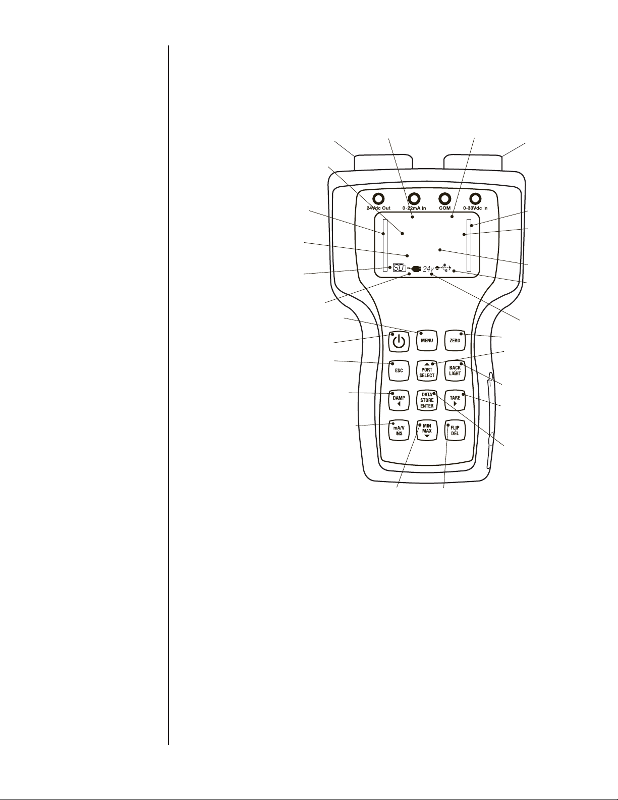
SECTION 4 BASE UNIT OVERVIEW
The base unit functions as a host for the Quick-Select pressure
and temperature modules. The base unit includes two bays for
installation of pressure or temperature modules, an LCD graphic
display with back light, a key pad, a USB micro B receptacle for
communication with a PC, an SD memory card slot and banana
jack connections for DC voltage supply and signal monitoring.
The enclosure is rated to IP65 water resistant.
CHANNEL 1
MODULE
CH1 MODULEENGINEERING UNITS
CH1 MODULEBAR GRAPH
VOLT/MILLIAMP
INDICATOR
SD CARD
INDICATOR
USB/BATTERY
POWER INDICVATOR
MENU KEY
POWER
ESCAPE
DAMPING/
LEFT ARROW
MILLIAMP/VOLT
SELECT INSERT
CH1 MODULE
READING
-
0.12
in H20
0.000
volts
CH2 MODULE
READING
-
0.001
PSi
CHANNEL 2
MODULE
CH2 MODULE/
BAR GRAPH
EXTERNAL
VOLT/MILLIAMP
READING
USB INDICATOR
24VDC
POWER SUPPLY
INDICATOR
ZERO FUNCTION
PORT SELECT/
UP ARROW
BACK LIGHT
TARE/
RIGHT ARROW
DATA STORE/
ENTER
10
MIN/MAX FUNCTION/
DOWN ARROW
FLIP DISPLAY/
DELETE
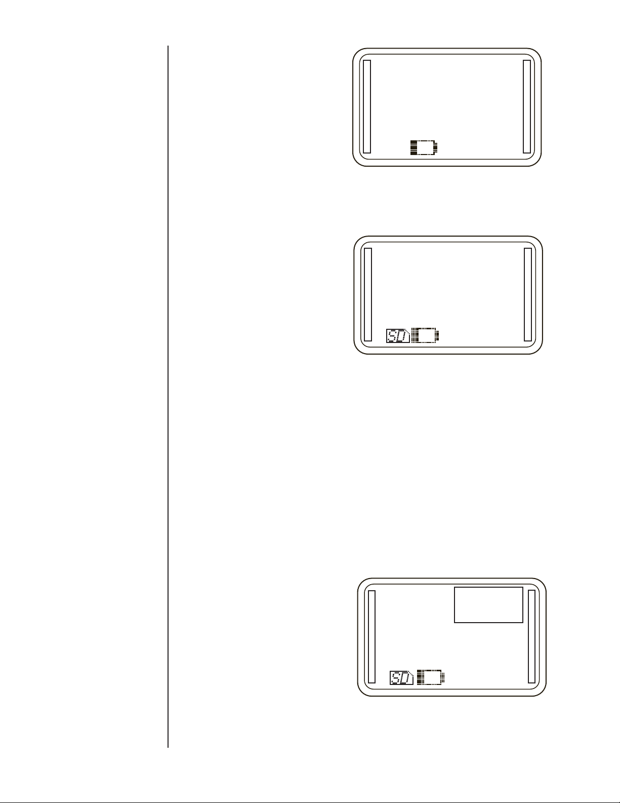
When pressure and or temperature modules are installed and
the base unit is powered on, it will briefly display the brand name,
data regarding installed modules. Then the HHC will go into measurement mode where it will display up to three values as well as
their respective engineering units of measure. The base unit is
pre-programmed with twelve units of pressure measurement, four
units of temperature measurement, DC voltage 0-30 VDC, DC
current 0-20 ma and also allows the user to program a custom
pressure unit of measure. In measurement mode, the display will
show Battery status, USB connection status, one or two vertical
bar graph indicators indicating percentage of full scale pressure
and other user interface and warning messages when applicable.
The calibrator is equipped with internal memory capable of
storing up to 16,000 records. Datalogs can be transferred to an
optional on board SD memory card to clear internal memory and
allow further data collection. Datalogs can be transferred to a PC
from the SD card and are presented in .csv files which can be
opened by Microsoft Excel software.
Page 13

SECTION 4 BASE UNIT OVERVIEW CONT.
The operator can program several parameters in the calibrator
which are further detailed in this manual. Programmable parameters include:
• Date and time
• Owner name
• Auto off time
• Port selection
• Select Voltage (v) or current (mA) monitoring
• Enable/Disable 24VDC power supply
• Zero modules
• Tare
• Damping
• Percent error function
• Engineering units select
• User defined unit of measure
• Dual sensor mode
• Pressure or Temperature switch test mode
• Calibration of base unit
• Module calibration
• Datalogging via USB
• Datalogging to internal memory
• Transfer datalog to SD card
SECTION 5 HOW TO OBTAIN PROGRAMMING
PASSCODES
USB PORT SD CARD PORT
USB MICRO B
CONNECTOR
Owner name and base unit calibration functions are password
protected. The passwords may be obtained by contacting the factory or downloading the “HHC Secure” application from the web
site. “HHC Secure” will generate the HHC’s unique pass codes
based on user input of the base unit serial number. Make a note
of these pass codes
Owner Pass code_______________________________
Calibration pass code _________________________________
SECTION 6 QUICK-SELECT MODULE
OVERVIEW
Quick-select modules are available for measuring a wide variety
of pressure and temperature ranges. They can be “hot swapped”
within the base unit while it is powered on without causing any
damage to the base unit or the module. “Hot Swap” refers to
installing or removing modules while the base unit is powered
on. The base unit will recognize the module and display the unit
of measure in which the module was originally calibrated and
labeled. Quick-Select pressure modules are available in accuracies from ±0.1% to ±0.025% of span.
11
Page 14

SECTION 6 QUICK-SELECT MODULE
OVERVIEW CONT.
Quick-Select modules when installed in the base unit are referred
to as Channel 1 and Channel 2. Channel 1 is always the module
on the left side of the calibrator when it is held upright with modules at the top of the calibrator and the LCD display facing the
operator. Channel 2 is on the right side when the base unit is
held in the same position.
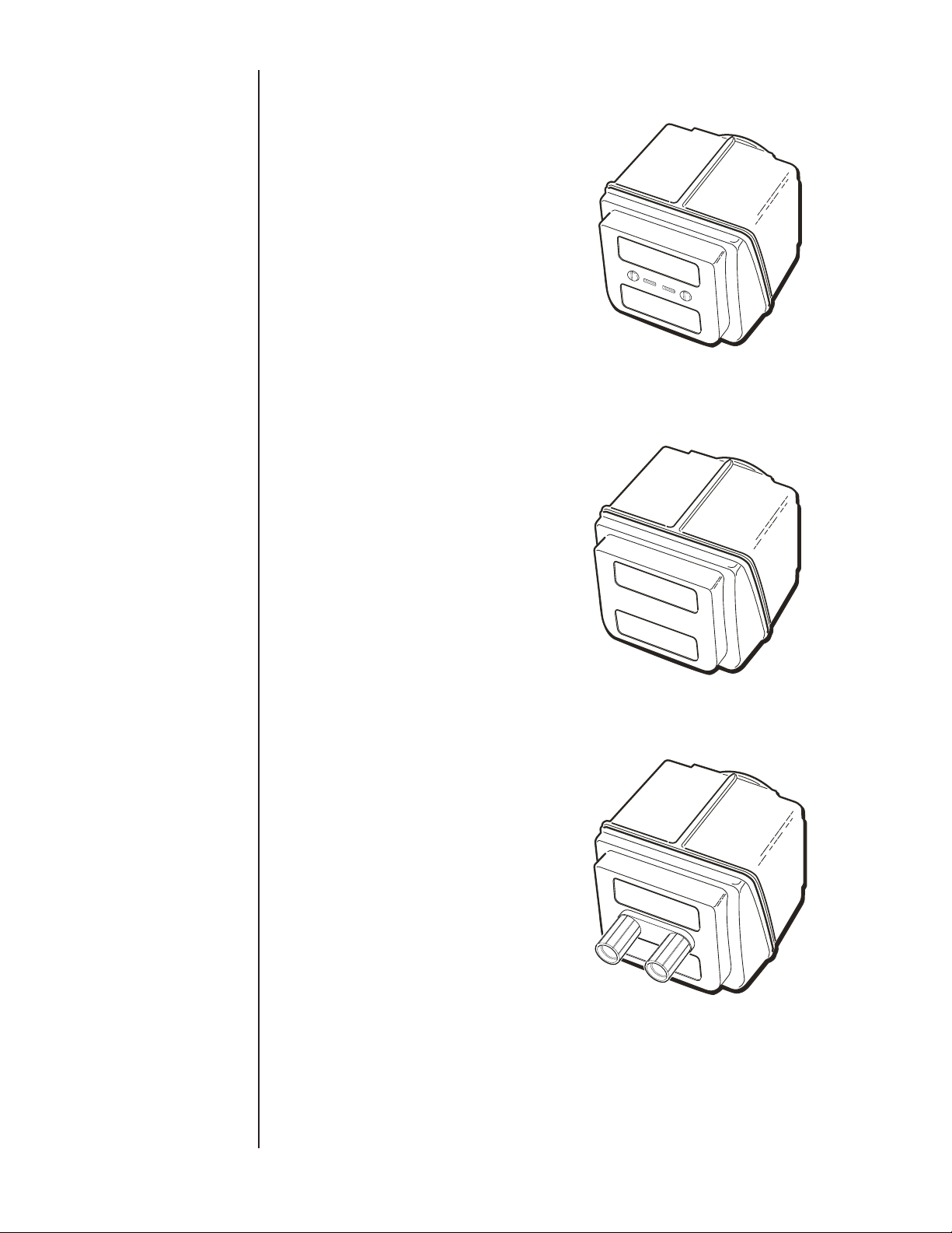
AM2-1 pressure modules are low pressure measurement devices
based on micro machined silicon variable capacitance sensors.
They are intended for use with clean dry, nonconductive, noncorrosive gases. They are available in ranges from 0.25 to 200
inches of water column and can be configured to provide differential, gauge or compound readings.
AM2-2 are high pressure measurement devices. They are single-port modules based on sensors capable of measuring gauge,
absolute, compound or vacuum with ranges spanning from
vacuum to 5 psi to 10,000 psi. All wetted parts are 316 stainless
steel (except for 10k psi module which has 17-4ph stainless
steel) and are intended for use with any pressure medium compatible with stainless steel.
AM2-RT1 and RT2 modules are RTD temperature measurement
modules compatible with Pt100, Pt1000, Ni120, Cu10, and up to
six user programmable resistance curves. Measurements can be
displayed in degrees Fahrenheit, Celsius, Kelvin, Rankin or ohms.
The setup menu allows the operator to choose configurations
for 2, 3 or 4 wire RTD probes. In addition, the setup menu also
allows selection of 1, 0.1, 0.01 or 0.001 decimals of resolution.
Accuracy specifications are detailed in the data sheet.
12
Page 15
SECTION 6 QUICK-SELECT MODULE
OVERVIEW CONT.
AM2-TC1 temperature modules read types J, K, T, E, R, S, B
and N thermocouples and display the measurement in units of
degrees Fahrenheit, Celsius, Kelvin, Rankin or millivolts.
System protection modules AM2-XS are used to protect unused
sensor bays in the base unit from moisture or other contamination ingress as well as EMI/RFI interference.
Calibration Module AM2-CM allows the operator to easily make
contact with internal connection pins necessary to apply the
required voltage levels for recalibration of the HHC base.
13
Page 16
SECTION 7 UNPACKING
SECTION 8 STORAGE
SECTION 9 CLEANING
SECTION 10 BATTERY INSTALLATION
Prior to removing the HHC from the packaging material, inspect
all cartons for shipping damage. Document any damage evident
in the event that a damage claim must be made against the shipper. After inspection, remove the base unit, module(s), manual
and any accessories purchased from the packaging material.
Retain the packaging for use in returning the HHC to the factory
for future calibration or repair.
Store in an area that is maintained in the temperature range
indicated in the storage temperature in the product specification,
-4/+158F (-20/+70C). Storage of product in environments that
will exceed this temperature limit increases the risk of product
damage.
Note: It is recommended that the product not be left in closed
cars or truck cabs as temperature damage can easily occur due
to drastic temperature changes.
Clean with a cloth moistened with a warm water/ mild detergent
mixture.
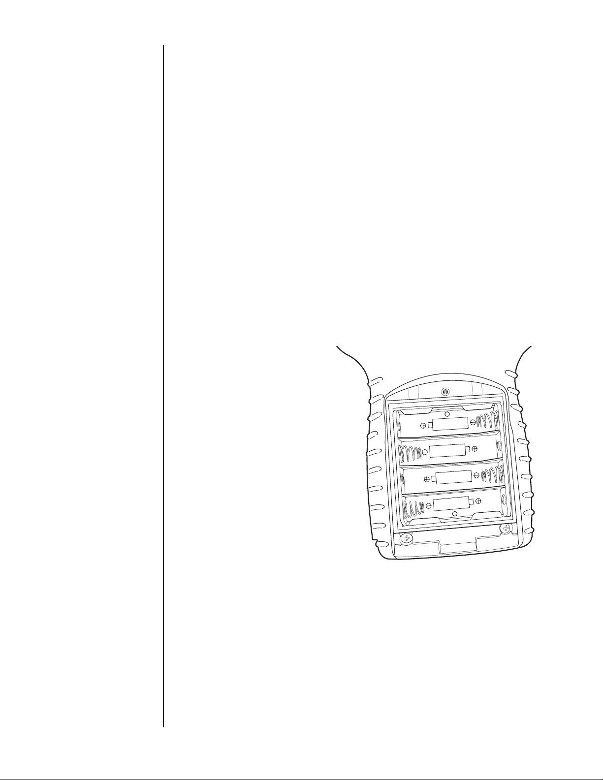
1. To gain access to the battery compartment, loosen the strap
assembly by detaching the Velcro connection and move the
strap to the side to allow access to the Phillips head screw on
the battery cover door.
2. Open the battery compartment by loosening the Phillips head
screw located in the battery compartment door immediately
above the product label.
3. Using thumb and forefinger gently lift battery door up and
toward the top of the calibrator to remove door.
OR U M-3X4
SIZE “AA” OR E QUIV
4. I nstall four new AA Alkaline batteries. (Only Duracell Alkaline
part number MN1500 for I.S. units.) Observe polarity markings
to install batteries correctly. Never mix old and new batteries.
5. Reinstall battery door. Be sure that the lower latch tab is
engaged beneath the clasp hook to ensure proper watertight
sealing of the battery compartment.
6. Tighten Phillips head screw in top of cover.
7. Replace strap by tightening strap and secure with Velcro.
Note: if unit will be stored for six months or more be sure to
remove batteries before storage to prevent possible battery
leakage.
14
Page 17
SECTION 11 MODULE INSTALLATION
1. Hold the base unit, in one hand, with the keypad side DOWN.
2. Holding the Quick-Select module to be installed in the other
hand, align the module with the locking tab up, with the module
bay on the base unit.
3. Slide the Quick-Select module into the base unit until the
retaining/release tab catches in the square cutout in the module
bay of the base unit. This will lock the Quick-Select module into
the base unit. Installation is now complete
Note:
If only one module is to be used, install the Quick-Select System
Protection module provided. Follow the same procedure to install
the system protection module as described above.
SECTION 12 STARTUP BASIC FUNCTION
Removal of Quick-Select modules
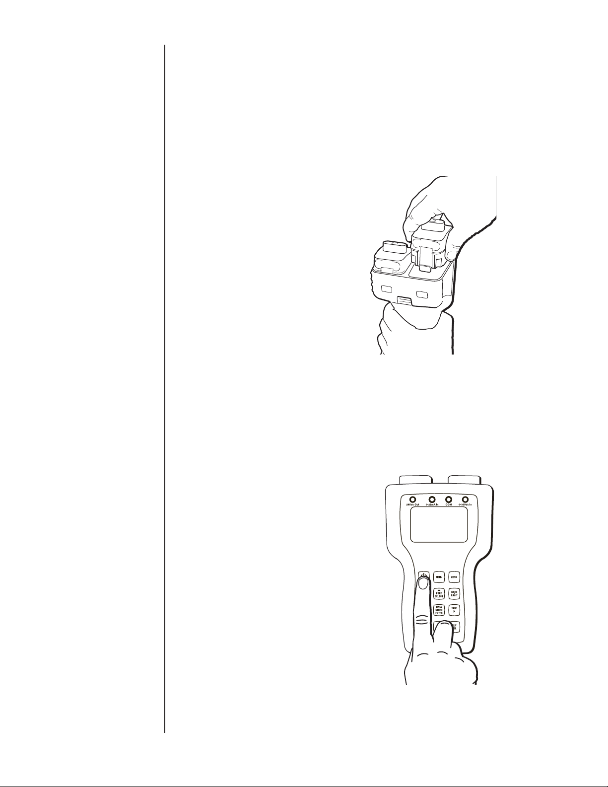
1. Hold the base unit, in one hand, with the keypad side DOWN.
2. Press the locking tab DOWN to release the module.
3. Grasp the Quick-Select module to be removed in the other
hand and gently pull to remove the module. There may be significant resistance to pulling due to O-ring seals on the module
needed to maintain water tight integrity.
After the desired Quick-Select module(s) have been installed,
power the calibrator on by pressing the green power key.
0.86
0.054
inH20
PSI
When powering on, the LCD display will briefly indicate the
calibrator model number, serial number, owner information
and whether it is an intrinsically safe or not intrinsically safe
model. If pressure or temperature modules are installed, serial
15
Page 18
SECTION 12 STARTUP BASIC FUNCTION CONT.
number, range and calibration data for each module will be briefly
displayed before booting up in Measurement Mode.
-
0.17
inH20
The HHC is now ready for basic pressure or temperature
measurement.
Pressure readings from installed modules will be displayed in the
engineering unit in which the module was originally calibrated.
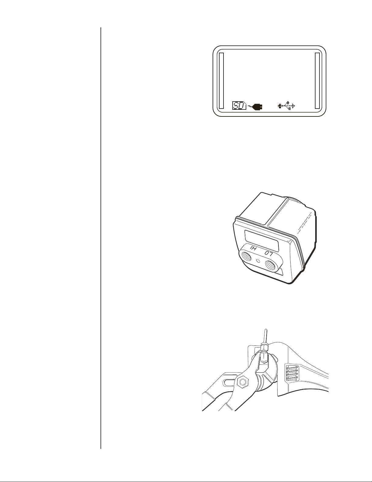
Connect the pressure port(s) of the Quick-Select pressure module(s) to be used to the pressure source to be measured. If a
gauge pressure measurement is to be made using a low differential pressure Quick-Select pressure module, be sure to connect
the pressure to be measured to the high pressure port on the
Quick-Select pressure module.
-
0.004
PSi
Note: When making connections to pressure ports on QuickSelect modules always use proper tools such as the proper size
wrench, slip joint pliers or locking jaw pliers to hold the stainless
steel manifold and use a second tool such as a properly sized
wrench to tighten the connection. NEVER tighten the fitting by
holding it only in the base unit
For temperature measurement, connect the RTD probe to be
used to the Switchcraft connector on the interface module then
proceed to Section 15j or 15k for instructions on setting up the
calibrator for temperature measurement.
16
Page 19
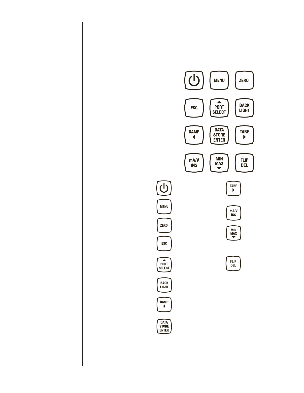
SECTION 13 KEY FUNCTION OVERVIEW
The most common functions are accessible by dedicated keys on
the keypad. More complex and less often used functions and programmable features are accessible through an easy-to-navigate
MENU system. A number of the keys have different functions
depending in which mode the HHC is operating. These keys have
white and yellow lettering and icons. The white lettering indicates
the primary key function. Yellow is the secondary function. A brief
overview of the keypad keys and functions follows:
Power Key is used to
switch the HHC on and off.
The MENU key is used to
enter and exit the programming MENU
To Zero installed QuickSelect Pressure modules
Escape Key to go back one
level when in MENU Mode
or to escape any special
display mode. Also aborts
auto datalogging.
To select installed modules
to apply various f unctions.
In MENU Mode, to increment a selected parameter
up once per press.
To switch back light on
and off.
To adjust damping level of
installed module(s) in Measurement Mode. In MENU
Mode it is used as a LEFT
ARROW key.
Multi-function key. In
Manual Datalog Mode,
stores one data point of
value presently shown on
the display. When in Automatic Datalog Mode will
begin or end auto logging
at the programmed interval. When in programming
mode, it is used as the
Enter key to save selected
parameters.
Used to activate the tare
function on installed
Quick-Select modules when
in Measurement Mode. In
MENU Mode used as RIGHT
ARROW key.
T o activate measurement of
milliamps or DC voltage in
Measurement Mode.
To display Minimum and
Maximum measured values
in Measurement Mode for
selected channels. In MENU
Mode, it is used to increment
a selected parameter DOWN
once per press.
To rotate LCD display 180°
in Measurement Mode. In
Programming Mode to zero
numeric characters or change
alpha characters to a blank
space.
17
Page 20
SECTION 14 a. ESC FUNCTION
During any programming operation pressing the ESC key will
cause the HHC to exit any special display mode or, step back one
programming level if in Programming Mode.
SECTION 14 b. PORT SELECT FUNCTION
SECTION 14 c. DATA STORAGE FUNCTION
PORT SELECT function is used in several programming applications including zero, min/max, tare and damping. This allows
the user to choose between installed modules to which an action
is to be performed. PORT SELECT is enabled following the initialization of a desired function such as zero. The selected module(s) will be indicated by having a rectangular box surrounding
the measurement indication. Pressing the PORT SELECT key
repeatedly will allow the user to select the Channel 1 , Channel
2 or both channels if applicable. When desired channel (s) are
selected the ENTER key is pressed to finalize the selection.
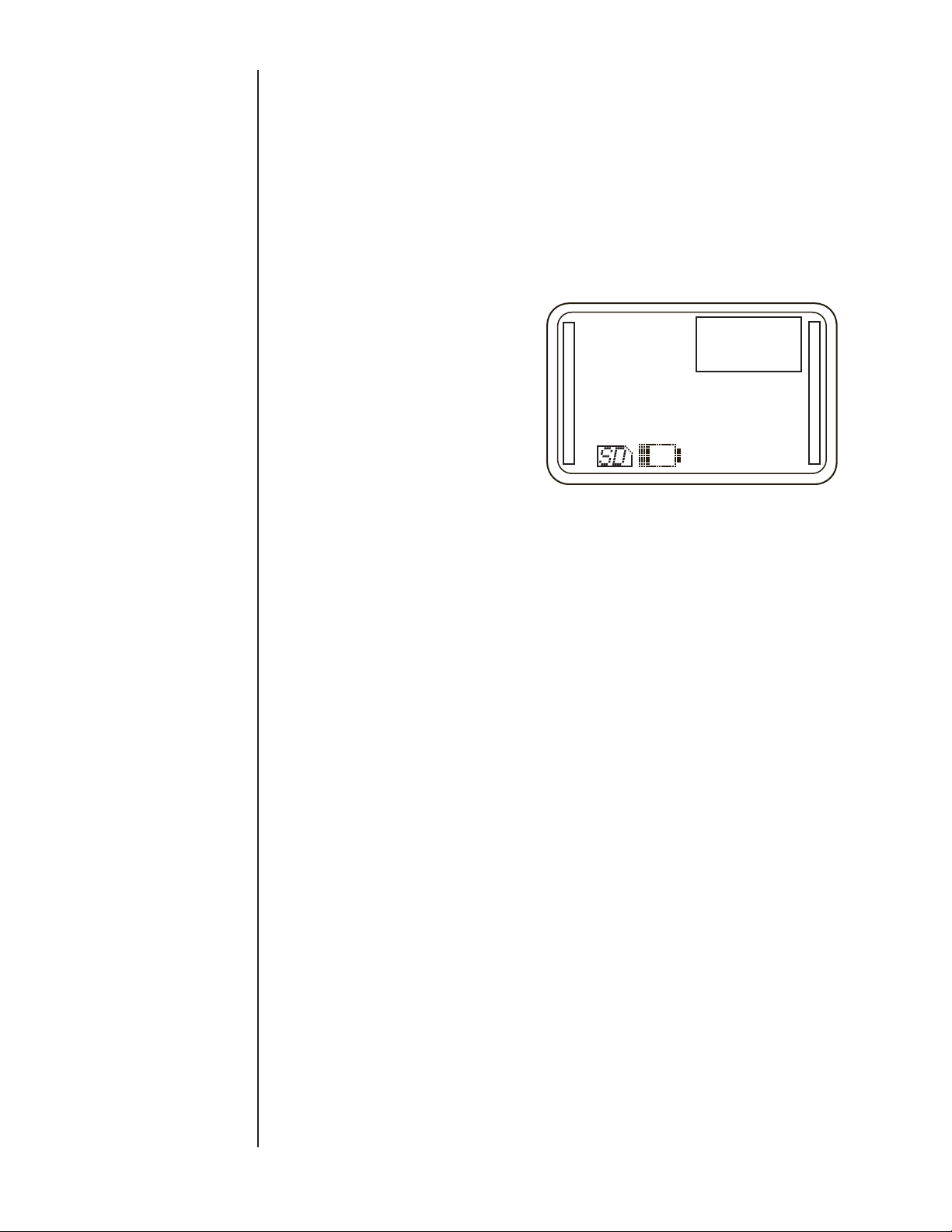
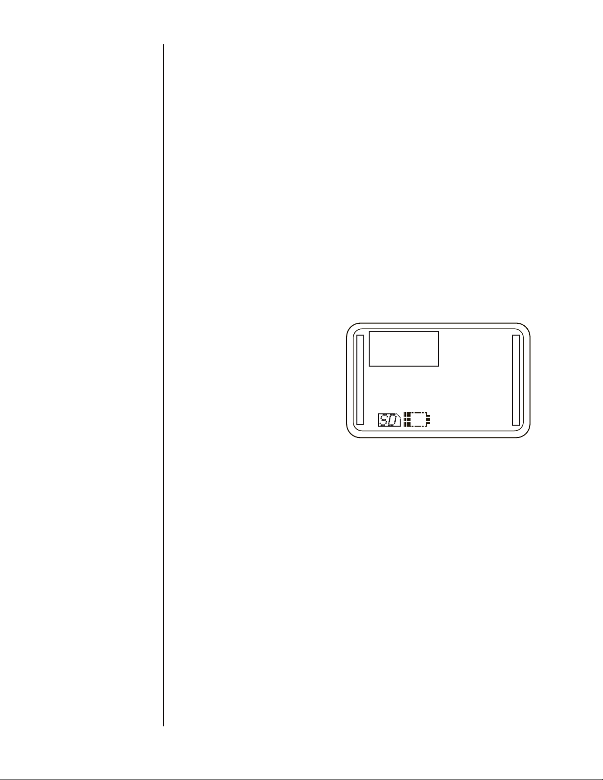
-
–
0.12
in H20
The default Data Storage mode is manual and is described in
section 14g and 15f. The HHC is capable of storing pressure,
temperature, voltage or current data for any combination of
installed modules, voltage or current inputs that are active, up
to three simultaneous data points. Each data record will include
a time stamp and up to three measurement values. Headers in
the Datalog report label columns with date, user-programmable
module description (default values are Channel 1, Channel 2,
Ext.) and the engineering unit of measure. Up to 16,000 records
can be recorded. Data records are grouped in Datalogs which
can be manually initiated or automatically logged at user definable time intervals between 100 milliseconds and 24 hours.
0.012
PSi
SECTION 14 d. ZERO FUNCTION
SECTION 14 e. BACK LIGHT FUNCTION
Utilized to remove zero offset, up to 10% of full scale range, when
zero pressure is applied.
1. Press the ZERO key. PORT SELECT MENU is entered with
the Channel 1 module selected.
2. Use the PORT SELECT key to select Channel 1, Channel 2 or
both Channels.
3. Press ENTER to zero the selected module or modules, or
press ESC to cancel and return to Measurement Mode
A module must be installed in the HHC base unit to be zeroed.
Additionally, it must be a pressure module, and must be within
10% of full scale of its factory programmed zero.
In the event an attempt is made to zero a module that is absent,
or which is not a pressure module a warning will be displayed in
the notice area stating:
“CH(X) not a pressure mod”.
In the event an attempt is made to zero a module that is more
than 10% of full scale from its factory programmed zero, a warning will be displayed in the notice area stating:
“CH(X) zero out of bounds”
Press the Back Light key to toggle the light on/off. A user programmable back light auto off timer can be used to preserve
battery life. Press any key to reset the backlight auto off timer.
18
Page 21
SECTION 14 f. DAMPING FUNCTION
The Damping Function stabilizes a measured pressure signal.
When damping is activated, the value displayed, saved to a
Datalog or transmitted to a journal (eg. To HyperTerminal) is a
filtered value. The filtering is programmable to 16 incremental
levels, allowing the damping function to be tailored to the specific requirements of most any application. The default damping
level is 1. As the damping level is increased, additional electronic
filtering is applied and the response time is slowed. Values are
displayed on the HHC screen, and recorded by Datalogging at
the fastest update rate between 100 and 300 milliseconds, based
on how many inputs are active. As damping level is increased the
update time increases approximately 100 milliseconds per damping level. With a single pressure module installed and damping
set to maximum level 16 the display output can lag by up to 1.6
seconds from the actual process pressure. If two modules are
installed and or voltage/current monitoring is active the system
display and Datalog values lag will also increase. The longest
display lag with two pressure modules programmed for maximum
damping and the voltage/current monitor active is 4.8 seconds.
Set up of Damping Function
When in Measurement Mode:
1. Press DAMP key.
2. Press PORT SELECT key to choose Channel 1, Channel 2, or
both modules.
3. Press RIGHT ARROW and LEFT ARROW to move cursor to
desired damping level (16 possible positions).
SECTION 14 g. MANUAL DATALOG FUNCTION
-
–
0.12
in H20
0.012
PSi
<----------|----->
4. Press ENTER to save the value and activate damping.
Once established in the set up MENU the damping process may
be enabled or disabled through the use of the DAMP key on the
keypad. To activate/deactivate the damping function:
1. Press the DAMP key on the keyboard.
2. Press PORT SELECT key to choose Channel 1, Channel 2, or
both modules.
3. Press ENTER to activate damping. Damping level will be
indicated below units of measure.
The HHC has two Datalogging modes, Manual and Automatic. Manual mode is the default. Automatic Datalog mode is
described in MENU programmable features section 15f.
The first time the DATA STORE key is pressed following power
up of the HHC, a new Datalog file will be created. The Datalog
column headers will be labeled with date, user programmable
module description (default values are Channel 1, Channel 2,
Ext.) and the engineering unit of measure. Programming channel
and tag names are covered in the MENU driven Datalogging
set up section 15f. The first row of the Datalog will be populated
with measurements as shown on the LCD display. Subsequent
presses of the DATA STORE key will create manual data records
into this initial Datalog.
19
Page 22
SECTION 14 f. DAMPING FUNCTION CONT.
SECTION 14 g. MANUAL DATALOG FUNCTION
CONT.
To close a Datalog and prepare the HHC to begin a new Datalog
press the ESC key. The next press of the DATA STORE key will
begin a new Datalog and will continue to record data in the new
log with every subsequent press of the key.
Up to 64 individual logs can be stored in the on board memory
with a total of 16,000 individual records.
SECTION 14 h. TARE FUNCTION
The HHC has the ability to Tare (subtract an operator selected
value) from the displayed pressure measurement value of either
one or two installed Quick-Select modules. This function is applicable to pressure measurements only. This is most commonly
required in applications where a pressure pre-load, such as in a
weighing application, must be subtracted from the displayed pressure measurement. If the HHC is being used with two Quick-Select modules, independent tare values can be entered for each
of the pressure modules. When tare function is active bar graph
displays will indicate actual percentage of full scale pressure not
the tare value. When the HHC is in tare mode the word “tare” will
appear below the engineering units.
There are two methods to select a tare value, automatic and
manual. Automatic Tare Mode will subtract the actual pressure
applied to the module at the time tare function is activated.
Manual Tare Mode allows the operator to enter a pressure value
to be subtracted from the actual pressure applied to the module.
Automatic tare is the default condition. If Manual Tare Mode is
desired go to the section named Program Manual Tare Value
below the next section.
Activate Tare Mode
To activate either Automatic or Manual tare Mode.
When HHC is in Measurement Mode
Press TARE key
Press PORT SELECT key repeatedly to select Channel 1,
Channel 2, or both active pressure modules
Press ENTER
Selected modules are now in Tare Mode. The value displayed is
equal to the actual applied pressure less the tare value.
When TARE function is active the word “Tare” will be displayed
below the engineering units.
20
Page 23

SECTION 14 h. TARE FUNCTION CONT.
-
–
0.000
PSi
Tare
0.24
inH20
0.000
mA
Exit Tare Mode
Press TARE key
Press PORT SELECT key repeatedly to select Channel 1,
Channel 2, or both active pressure modules
Press ENTER
Selected modules are now in Measurement Mode without a tare
value.
Program Manual Tare Value:
Press MENU key
Press DOWN or UP ARROW key to highlight “Modes…”
Press ENTER
Press DOWN or UP ARROW key to highlight “Tare…”
Press ENTER
Press DOWN or UP ARROW key to highlight “CH1 auto/manual
or CH2 auto/manual”
Press ENTER
Press DOWN or UP ARROW key to highlight Auto or Manual
Select “manual” and press “ENTER” to advance to “Enter CHx tare”
Enter CH1 tare
00020.00000
^
p si
Enter to accept
Esc to cancel
Press left or RIGHT ARROW key to select digit
Press UP and DOWN ARROW keys to advance numeric values
When desired tare value is displayed
Press ENTER
The HHC will enter Measurement Mode.
Select Automatic Tare Mode
Note that the default tare mode is Automatic. Tare Mode will be
reset to automatic when the unit is turned off. It is unnecessary to
program automatic tare mode unless manual mode was used in
the same session.
Press MENU key
Press DOWN or UP ARROW key to highlight “Modes…”
Press ENTER
Press DOWN or UP ARROW key to highlight “Tare…”
Press ENTER
Press DOWN or UP ARROW key to highlight “CH1 auto/manual
or CH2 auto/manual”
Press ENTER
Press DOWN or UP ARROW key to highlight Auto or Manual
Select “auto” then press ENTER to exit back to Measurement
Mode
21
Page 24

SECTION 14 i. mA/V FUNCTION
The HHC has the capability to monitor either DC milliamp current
0-22 mA or DC voltage 0-33 Vdc. Use of this feature requires
connection to the voltage or current source via the 4mm “Banana
Jacks” located above the units LCD. Note that this calibrator can
monitor only one parameter, either voltage or current, at a time.
To monitor voltage connect the negative lead of the voltage
source to the socket labeled “COM” with a black ring surrounding
the socket. Connect the positive lead of the voltage source to the
red ringed terminal labeled “0-33Vdc In”.
To monitor current connect the negative lead to the black ringed
terminal labeled “COM. Connect the positive current source to
the red ringed terminal labeled “0-22mA In”.
Devices under test may be powered by an external power source,
or by the 24 Vdc power supply built into standard (non-intrinsically
safe) HHC base units. See wiring diagrams in section 14j.
Press the mA/V key to activate voltage and current monitoring.
Press again to rotate through Volts, mA and pressure only
measurement.
SECTION 14 j. WIRING DIAGRAMS
4/20 TRANSMITTER HOOK UP USING, INTERNAL SUPPLY
4/20
TRANSMITTER
+ –
+24V ma Comm Vdc
4/20 TRANSMITTER HOOK UP USING, EXTERNAL SUPPLY
24 Vdc
+
EXTERNAL
SUPPLY
–
+24V ma Comm Vdc
4/20ma
TRANSMITTER
+ –
V OUT TRANSDUCER HOOK UP USING, INTERNAL SUPPLY
V OUT
TRANSDUCER
24 Vdc
SUPPLY
+
–
+
V OUT
TRANSDUCER
–
+ –
+24V ma Comm Vdc
V OUT TRANSDUCER HOOK UP USING, EXTERNAL SUPPLY
EXTERNAL
+24 ma Comm Vdc
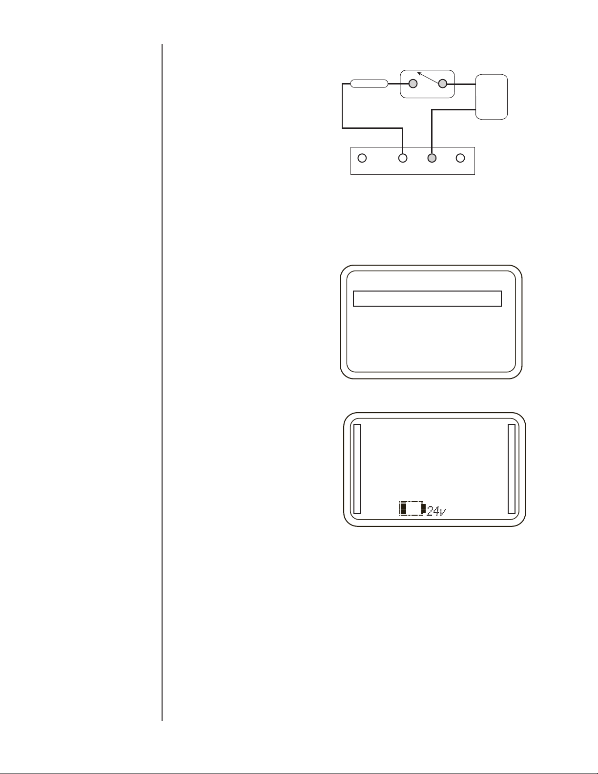
Note that you can use a normally closed switch as well
SWITCH HOOKUP
USING INTERNAL
SUPPLY SWITCH
NORMALLY OPEN
24Vdc Out
0-22mA In
COM
0-33Vdc In
22
EXTERNAL
24 VDC SUPPLY
+
–
24Vdc Out
0-22mA In
SWITCH HOOKUP
USING INTERNAL
SUPPLY SWITCH
NORMALLY OPEN
COM
0-33Vdc In
Page 25
+
–
0-33Vdc In
COM
24Vdc Out
0-33Vdc In
0-22mA In
COM
SWITCH HOOKUP
USING INTERNAL
SUPPLY SWITCH
NORMALLY OPEN
EXTERNAL
24 VDC SUPPLY
SECTION 14 j. WIRING DIAGRAMS CONT.
RESISTOR*
SWITCH HOOKUP
USING INTERNAL
SUPPLY SWITCH
NORMALLY OPEN
EXTERNAL
24 VOLT DC
+
–
SECTION 14 k. 24 VDC POWER SUPPLY ENABLE
AND DISABLE
24Vdc Out
*Resistor should be sized to allow current as follows:
2 mA < I < 36 mA, 2 mA 12 k , 35 mA 686
0-22mA In
COM
0-33Vdc In
Enable and Disable 24 Vdc Power Supply
(Non-intrinsically safe version only)
Press MENU key
Press DOWN or UP ARROW key to highlight “24v Loop Supply
On/Off”
Press ENTER
Main Menu
24v Loop Supply On/Off
Units…
Setup…
Modes…
Calibrate…
HHC will return to Measurement Mode and “24v” is shown on
center bottom of display to indicate power supply is activated.
–0.07
inH2O
0.005
psi
To Disable 24V Power Supply
Press MENU key
Press DOWN or UP ARROW key to highlight “24v Loop Supply
On/Off”
Press ENTER
HHC will return to Measurement Mode, “24v” has been removed
from the display. Power supply is now deactivated.
Note: In power supply off condition leakage of approximately
1.0 V and 0.03 mA will be measurable, this voltage and current is
not adequate to drive most loads.
Loop Power Overload and Reset
The 24v loop supply is rated to source up to 35 mA of current.
Overload protection is activated at approximately 54 mA. If the
load current exceeds this value, the overload protection function
deactivates the loop supply and will switch off the “24V” icon on
the LCD display. In the event of an overload the following Error
message will be displayed:
23
Page 26
SECTION 14 k. 24 VDC POWER SUPPLY ENABLE
AND DISABLE
0.10
inH2O
15.34
PSi
0.000
mA
Loop supply overloaded
Remove the excessive load from the circuit and attempt to activate
the 24v loop power supply via the MENU as described above.
If the excessive load is not removed from the circuit upon activation, the loop supply will be disabled and the following warning
message will be displayed
0.11
inH2O
15.29
PSi
0.033
mA
Loop supply reset failed
Note: A direct short between 24Vdc out and COM terminals will
cause complete shut down of the base unit. Remove shorted leads
and power the HHC on with the power key. Base unit will not be
damaged, however warning messages will not be displayed.
If the user correctly removes the excessive load and resets the
loop supply successfully via the MENU 24v loop supply indicator
turns back on and normal function is restored.
SECTION 14 l. MIN/MAX FUNCTION
Display the minimum and maximum pressure or temperature
readings measured by the installed modules. This function can
be performed once the HHC has been powered on, module “hot
swapped” into the HHC, or values that were zeroed.
Min /Max function is actively updating the display continuously
once it is activated.
To enter Min/Max mode
Press Min/Max key
Press PORT SELECT key to select Channel 1, Channel 2, or
both modules.
Press the ENTER key
-
–
0.12
in H20
0.012
PSi
24
Page 27

SECTION 14 l. MIN/MAX FUNCTION CONT.
Max: 6.21
Min: –11.20
inH20
–
0.010
PSi
0.000
mA
To clear active Min/Max measurements press the ZERO key.
To exit Min/Max mode completely press the ESC key.
Note: Datalogs recorded while in Min/Max Mode will record the
real time pressure measurements at the time of writing to the
Datalog, not the min/max values. If minimum and maximum
values occur between log entries, the data will NOT be included
in the Datalog.
SECTION 15 MENU MODE FUNCTIONS
SECTION 15 a. MENU MODE GENERAL KEY
FUNCTIONS
MENU Mode is where more sophisticated HHC functions are
programmed. Not all users will need to access all features available in MENU Mode. Some features, such as setting user name,
date and time will be done once or twice in the life of the calibrator. Others such as transferring Datalogs may be used several
times per day. There are several safeguards built into the HHC to
prevent a user from accidentally changing parameters or deleting
information. Be aware that there are functions such as erasing
Datalog memory that are permanent and cannot be restored
once they are completed.
MENU key
Enter MENU Mode by pressing the MENU key
Exit MENU Mode directly to Measurement Mode at any time by
pressing the MENU key
ESC function
During any MENU operation pressing the ESC key will prompt
the unit to step back one programming level.
ENTER function
The DATA STORE/ENTER key is a dual function key. In MENU
Mode this key is used to acknowledge and save a parameter
being programmed or selected.
UP and DOWN ARROW keys
PORT SELECT/UP ARROW and MIN/MAX/DOWN ARROW keys
are dual function keys. When in Menu Mode these keys are used
25
Page 28

SECTION 15 a. MENU MODE GENERAL KEY
FUNCTIONS CONT.
to move the selection box in a MENU UP or DOWN, and are also
used to scroll through programmable parameters such as alpha
numeric characters when programming names.
LEFT and RIGHT ARROW Keys
DAMP/LEFT ARROW and TARE/RIGHT ARROW keys are dual
function keys which are used in MENU Mode to move the cursor
to the right or left.
FLIP/DEL key when in Programming Mode is used to zero a
numeric character or advance an alpha character to a blank
space.
Upon entering MENU Mode the display will show “Main Menu”
and a list of MENU selections will appear below.
Use the UP and DOWN ARROWs to scroll to the desired parameter then press ENTER to begin working with that parameter.
Main Menu
24v Loop Supply On/Off
Units…
Setup…
Modes…
Datalog…
SECTION 15 b. BASE UNIT SET UP
SECTION 15 b. i. Programming Date & Time
The HHC allows the user to set up several parameters which
remain stored in memory for the life of the base unit, or need to
be reprogrammed very infrequently. These parameters include
date, time of day, Owner, and auto off timers.
Note: Date and time will need to be reprogrammed following
factory replacement of the real time clock battery approximately
once every 6 years.
Programming Date and Time
Note: time is entered in 24 hour military format.
Press MENU key
Press DOWN or UP ARROW key to highlight “Setup…”
Press ENTER
Press DOWN or UP ARROW key to highlight “System”
Press ENTER
Press DOWN or UP ARROW key to highlight “Date/Time…”
Press ENTER
Enter Date/Time
MM/DD/YY HH:MM:SS
12/25/93 14:26:07
^
Enter to accept
Esc to cancel
Press LEFT or RIGHT ARROW to select numeric position for
month, date, year, hour, minute and second
Press UP or DOWN ARROW to change numeric values
When correct MM/DD/YY and HH:MM:SS values are displayed
press ENTER to accept and save
The HHC will save and exit to Measurement Mode.
Note: if an inappropriate date or time value is used, the HHC will
display an error message ”Date Set Failed” and prompt the user
to retry or abort the attempt to program.
26
Page 29

SECTION 15 b. ii. Programming Owner Name
Programming Owner Name (15 Characters max)
Press MENU key
Press DOWN or UP ARROW key to highlight “Setup…”
Press ENTER
Press DOWN or UP ARROW key to highlight “System”
Press ENTER
Press DOWN or UP ARROW key to highlight “Owner…”
Press ENTER
Owner Password screen appears. If the Owner Password is not
known, see section 5 to obtain owners password.
Owner Password
00000
^
Enter to accept
Esc to cancel
Press left and RIGHT ARROWs to position cursor beneath
desired character
Press UP and DOWN ARROWs to increment numeric characters
When the password is correct press ENTER
“Enter Owner name” screen appears
Note: If the incorrect password is entered, the HHC display will
show a message “Bad Owner PW”, and the user will be asked to
Retry or Abort.
SECTION 15 b. iii Program Auto Off Timers
Enter Owner Name
Joe Smith
Enter to accept
Esc to cancel
Press LEFT and RIGHT ARROWs to position cursor beneath
desired character
Press UP and DOWN ARROWs to increment alpha and numeric
characters
When the Owner name is correct press ENTER
The HHC will save and exit to Measurement Mode.
The HHC has two programmable auto off timers designed to
maximize battery life. The “Power Off” timer will shut down the
HHC base unit completely after a user selected time. The “Backlight Off” timer controls the backlight function only. It is possible to
have two different times programmed for these features. Selecting
the option “Never” for either function will disable the timer altogether and the user must manually switch the base unit and back
light on/off by pressing the proper key.
Note: When the HHC base unit is powered via the USB port or is
auto datalogging, auto off timers are both disabled.
Program Auto Off Timers
Press MENU key
Use DOWN or UP ARROW to highlight “Setup”
Press ENTER
Use DOWN or UP ARROW to highlight “System…”
^
27
Page 30

SECTION 15 b. iii Program Auto Off Timers Cont.
Press ENTER
Use DOWN or UP ARROW to highlight “Auto off timer…”
Press ENTER
Use DOWN or UP ARROW to highlight “Power off”…
OR
Use DOWN or UP ARROW to highlight “Backlight off”…
Auto Off Modes
Power Off…
Backlight Off…
Press ENTER
Use DOWN or UP ARROW to highlight desired time in minutes or
“Never”
Power Off Times
Never
5 Minutes
15 Minutes
30 Minutes
60 Minutes
SECTION 15 c. ENGINEERING UNITS SELECTION
Press ENTER
HHC will return to Measurement Mode with values being saved
Select Engineering Units
Press MENU key
Press DOWN or UP ARROW key to highlight “Units…”
Press ENTER
Press DOWN or UP ARROW key to highlight “Select Units”
Press ENTER
Press DOWN or UP ARROW key to highlight “Channel 1
Module”, “Channel 2 Module”
Press ENTER
Press DOWN or UP ARROW key to highlight desired engineering
unit
Select Ch1 Unit
psi
inH2O
inHg
kPa
1 of 13 units
Press Enter to select unit and exit to Measurement Mode.
Note: The HHC has 99,999 counts of resolution. The display is
capable of displaying five digits up to 99,999. Selecting engineering units which approach 99,999 counts of resolution could result
in the least significant digits to appear unstable.
Note: Units of measure whose full scale value exceeds 99,999
will not be available to be selected.
28
Page 31

SECTION 15 d. H2O TEMPERATURE CONVERSION
SELECTION
If the user selects an engineering unit which references water
column pressure, they can select a water temperature to factor
into the conversion. The pressure generated by a column of water
will vary with the temperature of the water. As there are industry
standard temperatures used as conversion factors when calibrating pressure measurement devices in terms of the height of a
column of water, the HHC uses three(3) conversion factors, (20°C
<factory default>, 60°F and 4°C).
The user may select one to use with the water column based
pressure units.
Temperature Selection for H2O Conversion Factor
To select the reference water temperature:
Press MENU key
Press DOWN or UP ARROW key to highlight “Units…”
Press ENTER
Press DOWN or UP ARROW key to highlight “H2O ref temp”
Press ENTER
Press DOWN or UP ARROW key to highlight “4 Deg C”, “60 Deg
F” or “20 Deg C”
Select H2O Ref
20C
60F
4C
SECTION 15 e. PROGRAMMING USER DEFINED
UNITS OF MEASURE
Press ENTER to select temperature and exit to Measurement
Mode.
If one of the preprogrammed engineering units of pressure measure is not acceptable, the user can program the HHC to read in
a user defined unit.
Note: That the conversion factor programmed is always programmed in relation to PSI engineering units regardless of the
pressure units that the pressure module is calibrated in. The
conversion factor is 1.0 PSI= X custom units.
Programming User defined Units of Measure for
Pressure Modules
Press MENU key
Press DOWN or UP ARROW key to highlight “Units…”
Press ENTER
Press DOWN or UP ARROW key to highlight “User Units”
Press ENTER
Press UP and DOWN keys to select “Name” or “Conversion
Factor”
Programming Unit of measure Name (up to 6 characters)
Select “Name”
Press ENTER
“Enter Unit Name” screen appears
Enter Unit Name
Newton
^
29
Enter to accept
Esc to cancel
Page 32

SECTION 15 e. PROGRAMMING USER DEFINED
UNIT OF MEASURE CONT.
Press left and RIGHT ARROWs to position cursor beneath
desired character
Press UP and DOWN ARROWs to increment alpha and numeric
characters
When the Unit name is correct press ENTER
HHC will return to “User Units” screen
Note: Unit of Measure names are limited to six characters.
Programming User Units Conversion Factor
Note: The User Units Conversion Factor is always programmed in
relation to psi engineering units regardless of the pressure units
that the pressure module is calibrated in. The conversion factor is
1.0 PSI= X custom units.
From the “User Units” Screen
Press the UP and DOWN ARROW keys to select “Conversion
Factor”
Press ENTER
“Enter Conversion” screen appears
Enter Conversion
00800.00000
^
Enter to accept
Esc to cancel
SECTION 15 f. DATALOG SETUP
Press left and RIGHT ARROWs to position cursor beneath
desired numeric character.
Press UP and DOWN ARROWs to scroll numeric values.
When desired numeric value is displayed in proper decimal
position press ENTER to accept.
HHC will save the value and exit to Measurement Mode.
The user defined unit of measure name will now appear in the list
of engineering units listed under the Engineering Units programming MENU and can be applied to any active pressure module
installed in the HHC.
The HHC includes manual and automatic logging. Manual logging is performed by pressing the DATA STORE key. This action
will save the measured values presently read in a Datalog in the
internal memory of the HHC. Automatic Datalogging allows the
user to program a timed interval between measurements which
will be saved in one Datalog in the internal memory.
Up to 64 individual logs can be stored in the on board memory
and a total of 16,000 individual records.
Default Datalog tag names are as follows:
Datalog name XXMMDDYY, XX= sequential number of Datalog
(01-64). Datalog name is generated by the HHC and is not user
programmable.
The default channel tag names are:
Channel 1 = CH1
Channel 2 = CH2
Voltage or current monitor = Ext
30
Page 33

SECTION 15 f. i. Program Channel Tag Names
Program Channel Tag Names (up to 7 characters)
The default channel names, Channel 1, Channel 2 and Ext can
be re-programmed by the user.
Press MENU key
Use DOWN or UP ARROW to highlight Datalog…
Press ENTER
Use DOWN or UP ARROW to highlight Set channel tags……
Datalog
Manual/Auto
Review data
Set channel tags
Export to SD
Clear internal storage
Press ENTER
Use DOWN or UP ARROW to highlight Channel 1, Channel 2 or
external input…
Press ENTER
Display will show “Enter CH 1 Tag”
Enter CH1 tag
Ch1
^
SECTION 15 f. ii. Program Auto Datalog Time
Enter to accept
Escape to cancel
“^“ Beneath a character or space indicates which character in the
tag name is being configured.
Use the DOWN or UP ARROW to scroll through alpha and
numeric characters
Note: Pressing the DEL key will advance the alpha numeric character to the blank space character which is the divider between
numeric and lower case alpha characters.
Use the left and RIGHT ARROWs to move the cursor.
When tag name is displayed as desired press ENTER
Display will return to the “Select Channel” MENU
Choose another channel to program or press MENU to exit
to Measurement Mode or ESC to move back to the “Datalog
“MENU.
Program Auto Datalog Time
Auto Datalogging allows the user to program a Datalogging interval between 0.1 second and 86,400 seconds (24 hours).
Press MENU key
Use DOWN or UP ARROW to highlight “Datalog…”
Press ENTER
Use DOWN or UP ARROW to highlight “Manual/Auto…”
Press ENTER
Use DOWN or UP ARROW to highlight Manual or Auto, select
“Auto”…
Press ENTER
Display will show “Set Log Interval”
31
Page 34

SECTION 15 f. ii. Program Auto Datalog Time
Cont.
Set log interval
Desired: 00001.0 sec
Actual: 00001.2 sec
Enter to accept
Esc to cancel
“^ “Beneath a digit indicates which character in the time interval
name is being configured.
Press UP or DOWN ARROW to scroll through numeric values
Use left or RIGHT ARROW to move cursor to next desired
position.
When the desired time interval in seconds is displayed, press
ENTER
The HHC will return to Measurement Mode.
*NOTE*
Note: When programming, the display will show “Desired” interval
and “Actual” interval. Actual interval may not match the desired
value. The minimum sample rate changes are based on the
number of inputs installed in the base unit. The sample rate
increase 0.1 seconds per input (0.1, 0.2 or 0.3 seconds). The
actual interval must be an even multiple of this value. For example, if there are two pressure modules and a voltage input active,
the minimum sample rate is 0.3 seconds or even multiples of 0.3
seconds. If the desired value entered is 0.1 seconds the actual
value will remain 0.3 seconds.
SECTION 15 f. iii. Initiate Auto Datalog
SECTION 15 f. iv. Initiate Manual Datalog
Initiate Automatic Datalog
To initiate an automatic Datalog after programming desired channel tag names and logging interval press DATA STORE key. The
display will show a message saying “Auto-logging”
-
0.11
inH20
-
0.011
PSi
0.000
Auto–logging
To disable auto logging press either DATA STORE key or ESC key.
Initiate a Manual Datalog
After programming desired channel tag names
Press MENU key
Use DOWN or UP ARROW to highlight “Datalog…”
Press ENTER
volts
32
Page 35

SECTION 15 f. iv. Initate Manual Datalog Cont.
Use DOWN or UP ARROW to highlight “Manual/Auto…”
Press ENTER
Use DOWN or UP ARROW to highlight Manual or Auto, select
“Manual…”
Press ENTER
Display will return to Measurement Mode.
Press DATA STORE to begin a new manual Datalog.
Display will briefly show “Data point Taken” then will display
“Manual log enabled”
-
0.11
inH20
-
0.011
PSi
0.000
Manual log enabled
Subsequent presses of DATA STORE will add one new data point
for each key press.
To close a manual Datalog press ESC
The next press of Datalog key will begin a new Datalog file.
volts
SECTION 15 f. v. Review Datalog Data
Datalogs stored on the internal memory can be reviewed on the
HHC display.
Review Datalogs
Press MENU key
Use DOWN or UP ARROW to highlight Datalog…
Press ENTER
Press DOWN or UP ARROW to highlight Review data…
Press ENTER
“Select datalog” screen will appear.
Select datalog
01.05/27/2014
Ch1: inH2O
Ch2: psi
Ext: volts
5 records
Use up and DOWN ARROWs to scroll through saved Datalogs.
Press ENTER when desired name appears
Review Data screen appears
Review data
09:41:54.47
Ch1: 0.11 inH2O
Ch2: 46.96 psi
Ext: 24.134 volts
Record 1 of 5
Press DOWN or UP ARROW to review individual data records.
Exit Data review mode completely by pressing MENU.
33
Page 36

SECTION 15 f. v. Review Datalogs Cont.
SECTION 15 f. vi. Export Datalogs to SD Card
Or
Press ESC to go back to “Select Datalog” screen and choose
another log to review.
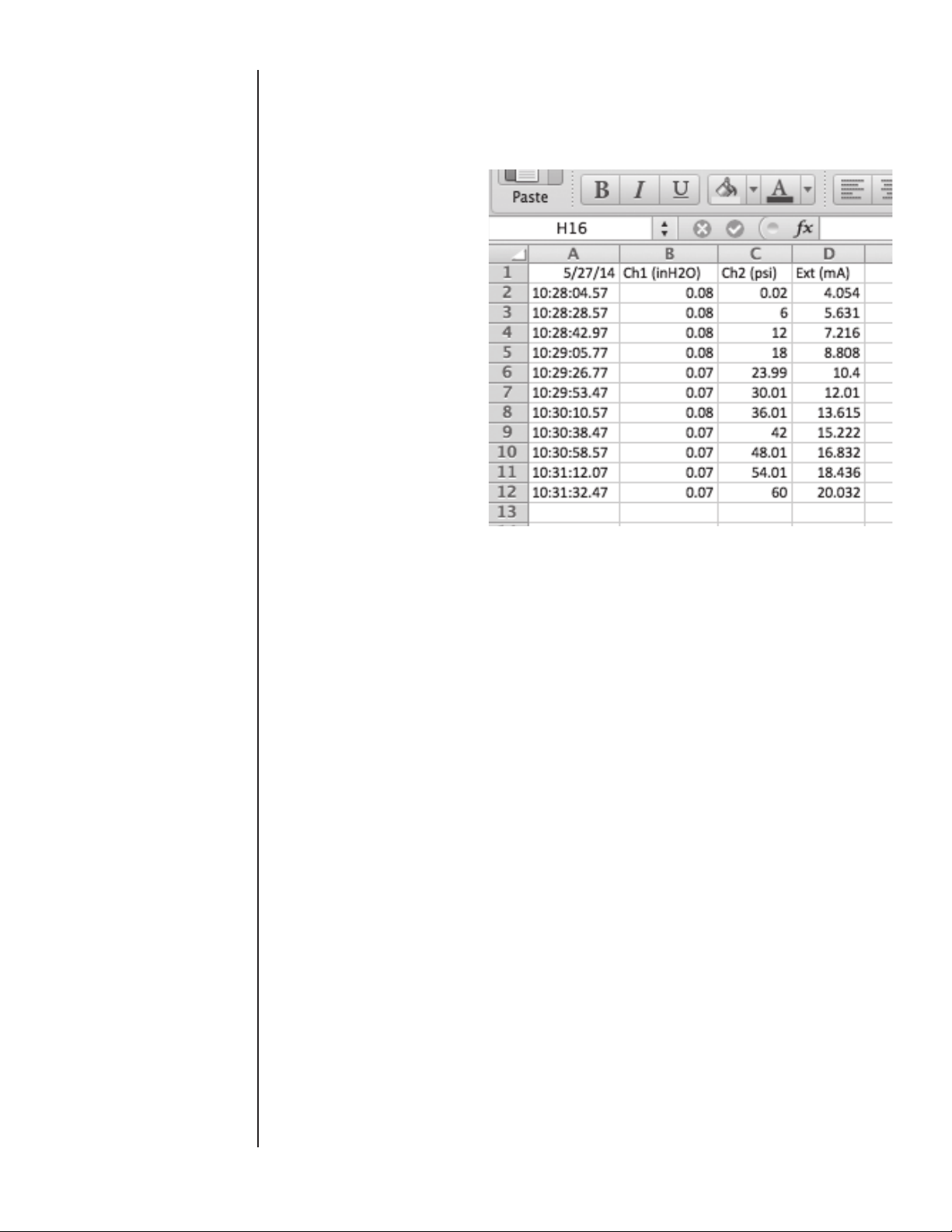
The HHC contains a slot for a standard SD memory card. When
a card is installed Datalogs can be exported to the card in .CSV
(Comma Separated Values) files which are able to be read by
Microsoft Excel or other spread sheet software. One .CSV file is
generated per Datalog.
Datalog file name XXMMDDYY, XX= sequential number of Datalog (01-64). Datalog name is generated by the HHC and is not
user programmable.
TO EXPORT DATALOGS
Press MENU key
Use DOWN or UP ARROW to highlight Datalog…
Press ENTER
Press DOWN or UP ARROW to highlight “Export to SD”
Datalog
Manual/Auto…
Review data…
Set channel tags…
Export to SD
Clear internal storage
SECTION 15 f. vii Clear Internal Memory Storage
Press ENTER
“Exporting logs” screen will appear and remain on until transfer
operation is complete.
When the export process is completed successfully a message
reading “Exported logs to SD” will appear briefly before the HHC
returns to Measurement Mode.
Exp orting log s…
Exporting datalogs to
SD card. This may take
a little while.
Datalogs will appear in a folder on the SD card labeled
DATALOGS.
If a new or formatted SD card is used the HHC will create the file
folder and deposit the logs there.
Note: if an SD card is not installed or if there is a problem writing the Datalog to the SD card a warning message “No SD card
present” will be displayed. Check that the SD card is installed
properly in the slot and attempt to download again.
WARNING: This command PERMANENTLY DELETES ALL
Datalog FILES stored in the internal memory. This
process does not effect datalogs transferred to
the SD card.
Press MENU key
Use DOWN or UP ARROW to highlight “Datalog…”
Press ENTER
Press DOWN or UP ARROW to highlight “Clear Internal Storage”
Press ENTER
“Delete all logs?” screen will appear
34
Page 37

SECTION 15 f. vii Clear Internal Memory Storage
Cont.
SECTION 15 g. SWITCH TESTING FUNCTION
Delete all
logs?
Are you sure you want to
clear all internal storage?
Yes
No
Use DOWN or UP ARROW to highlight Yes or No
Press ENTER
Selecting “no” will return to the Datalog MENU
Selecting “yes” will proceed to “Clearing Logs…” screen.
Clearing log s…
Clearing all internal
storage: this may take
a little while.
When the operation is complete the HHC will return to
Measurement Mode.
The HHC can be used to test pressure and temperature switches.
Onboard firmware provides the ability to verify switch trip point,
reset point and to calculate deadband of a pressure switch.
The HHC looks for a change of state that produces either 2 volts
or a 2 mA change across the corresponding voltage or current
input terminals.
Prior to initiating this test procedure the required electrical set up
should be configured to provide the necessary signal levels per
the wiring diagrams presented in section 14j.
Note: Switch test requires slow changes in process pressure. See
damping to minimum setting.
Set up switch test
The operator must program the following parameters before
beginning switch testing:
• Measurement Channel (Channel 1, Channel 2)
• Input Signal type (Voltage or current)
• Switch type (Normally open or closed).
• See wiring diagrams in Section 14j
Press MENU key
Use DOWN or UP ARROW to highlight “Modes…”
Modes
Dual module functions…
Percent error…
Switch testing…
Communications…
Press ENTER
Use DOWN or UP ARROW to highlight “Switch testing…”
Press ENTER
35
Page 38

SECTION 15 g. SWITCH TESTING FUNCTION
CONT.
Use DOWN or UP ARROW to highlight “Measurement Channel…”
Press ENTER
Use DOWN or UP ARROW to highlight “CH1” (Channel 1
module) or “CH2” (Channel 2 module)…
Press ENTER
HHC will go back to Switch Testing MENU
Use DOWN or UP ARROW to highlight “Signal Type…”
Press ENTER
Use DOWN or UP ARROW to highlight “Current or Voltage…”
Press ENTER
Use DOWN or UP ARROW to highlight “Switch Type…”
Press ENTER
Use DOWN or UP ARROW to highlight “Normally Open or Normally Closed…”
Press ENTER
Display will briefly display the message “Begin Test” then immediately enter switch test mode.
27.876
Live(PSi)
---
Reset (PSi) DB(PSi)
In Switch Test Mode the display will initially show the Live pressure (pressure being applied at that time), and units of measure.
The switch trip point, reset point and dead band (DB) will be
blank indicated by “---“
Setup is now complete and switch testing can begin. Depending
on the options chosen above either apply additional pressure or
release pressure slowly.
Note: depending on number of modules installed the update rate
will be either 0.2 or 0.3 seconds. A rapid increase or decrease
in pressure near the switch setpoint can result in inaccurate
readings
When the switch opens or closes the pressure/temperature reading and units of measure will be displayed as “trip” point.
Slowly release or increase pressure (opposite of the action taken
in the earlier step) until switch state changes again. This value
will be displayed as the “reset” value along with units of measure.
The deadband (DB) will also be calculated and displayed. This
value is the difference between the trip point and reset point.
Trip(PSi)
---
---
28.241
Live(PSi)
28.412
Reset (PSi) DB(PSi)
If desired, record the readings displayed on the screen. These
values are not included in the manual Datalog.
To reset switch test and maintain the same parameters press the
ZERO key to return to initial testing screen.
To exit switch test mode press ESC
To enter Main MENU Programming Mode press MENU.
36
31.353
Trip(PSi)
2.942
Page 39

SECTION 15 h. PERCENT (%) ERROR FUNCTION
The Percent Error Function allows the user to display the output
from a device under test in terms of percent error of the full scale
range of that device. This function applies to the calibration of
both temperature and pressure devices. Percent error mode
eliminates the need for manual calculations to determine the level
of accuracy of the device under test.
The HHC is capable of comparing two measurements in several
configurations
• Pressure or temperature input to current output device, such as
a transducer with 4-20 mA output
• Pressure or temperature input to voltage output device, such as
a transducer with 0-10 Vdc output
• Pressure to pressure device, such as a pneumatic controller
• Current input to pressure output device such as a pressure
regulator with 4-20 mA input signal
All input and output parameters can be programmed by the
operator.
Datalogging is possible while using the HHC in Percent Error
Mode. Datalogs will include only the actual values measured. Datalogs will not include the percent error calculation as displayed
on the HHC screen.
For example, if the HHC is being used to calibrate a 0-100 psi
transmitter with 4-20 mA output the HHC will display the following
data:
• Input pressure, as measured by Quick-Select pressure module
in selected engineering units that is being applied to the device
under test. This is the standard against which the device under
test is being compared.
• Output, from the transducer under test in output units (milli-
amps)
• Percent error, calculated by comparing the theoretical milliamp
output of the device under test based on the measured pressure reading, against the actual measured output of the device
under test. The HHC will indicate whether this error is positive
or negative as compared to the theoretical output.
If 50.00 psi is applied to a 0-100 psi pressure transducer with a
1-5 Vdc output, the theoretical output will be 3.000v. If the measured output from the transducer is 3.015v, the HHC will display
the following:
50.000
In(PSi)
% error
% Error terms
Input refers to any pressure or electrical signal input to both the
device under test and the pressure or temperature module in the
HHC.
Input Channel refers either to a pressure or temperature module
installed in the base unit (CH1 or CH2), or a voltage or current
signal connected to the common and input jacks.
Input Range refers to the numeric full scale range of the input
parameter. It is not necessary to program an engineering unit for
the input range. For example, a pressure transducer with a measurement range of 0 to100 psi. The engineering unit is automatically determined by the channel selected (pressure, temperature,
voltage or current).
2.423
Out(volts)
0.38
37
Page 40

SECTION 15 h. PERCENT (%) ERROR FUNCTION
CONT.
Output refers to any output signal from the device under test.
Output channel refers to the channel on which the device under
test is sending its output signal. For example a pressure transducer with 0-10 VDC output would be connected to the HHC’s
External input, referring to the banana jacks labeled COM and
0-33 Vdc In.
Output range refers to the numeric range of the output of the
device under test. In the example above the range would be 0 to
10. Engineering units are determined by the channel on which
the output signal is transmitted.
There is no need to program parameters referring to modules
installed in the HHC as they are recognized by the base unit.
To set up the Percent Error Function the HHC must be properly connected to the device under test and have appropriate
Quick-Select modules installed.
If testing pressure transducers, a pressure source such as a
hand pump, regulated clean shop air or dry nitrogen is required
to apply pressure to the device under test and the HHC pressure
module.
Note: See section 14j for wiring diagrams.
If using the internal power supply be sure that it has been turned
on in the main MENU and “24v” is indicated on the display.
Note: If the device under test is a voltage or current output device,
the “mA/V” key must be used to activate current or voltage monitoring prior to programming the test parameters.
For the following procedure description assume that the device
under test is a pressure transducer measuring 10-110 psi with a
voltage output of 1-6 Vdc.
Programming set up for Percent Error function
Press MENU key
Use DOWN or UP ARROW to highlight Modes…
Press ENTER
Use DOWN or UP ARROW to highlight Percent error…
Press ENTER
Use DOWN or UP ARROW to highlight Input Channel…
Press ENTER
Percent Error
Input channel…
Input range…
Output channel…
Output range…
Enter % Error Mode
Use DOWN or UP ARROW to highlight “CH1” (Channel 1
Module) or “CH2” (CHANNEL 2 module) or “External Input…”
Press ENTER
HHC will go back to Percent Error MENU and advance to the next
programmable parameter...
Use DOWN or up ARROW to highlight “Input range…”
Press ENTER
HHC will display Input Range selection screen
38
Page 41

SECTION 15 h. PERCENT (%) ERROR FUNCTION
CONT.
Inp ut rang e
4-20
0-x
1-x
Custom
Use DOWN or UP ARROW to highlight 4-20, 0-X, 1-X or Custom
Note: If a range ending in “–X” or “Custom” is selected the operator
can program the numeric value for the variable as follows
If a custom range is required:
Use DOWN or UP ARROW to highlight “Custom”…
Note: programming of Custom and “X” values uses similar proce-
dures for setting numeric values and decimal positions.
Input Zero screen will be displayed.
Input Zero
00001.00000
^
Enter to accept
Esc to cancel
Press left and RIGHT ARROWs to position cursor (^) beneath
desired numeric character.
Press UP and DOWN ARROWs to scroll numeric values.
When desired numeric value is displayed in proper decimal
position
Press left or RIGHT ARROW to move cursor beneath the next
digit to be programmed.
When desired Zero input value is displayed on screen for example
00010.00000
Press ENTER to accept
Input FS (Full Scale) screen will be displayed.
Input FS
00006.00000
^
Enter to accept
Esc to cancel
Press left and RIGHT ARROWs to position cursor beneath
desired numeric character.
Press UP and DOWN ARROWs to scroll numeric values.
When desired numeric value is displayed in proper decimal
position
Press left or RIGHT ARROW to move cursor beneath the next
digit to be programmed.
39
Page 42

SECTION 15 h. PERCENT (%) ERROR FUNCTION
CONT.
When desired FS input value is displayed on screen for example
00110.00000
Press ENTER to accept
HHC will go back to Percent Error MENU and advance to the next
programmable parameter.
Use DOWN or UP ARROW to highlight “Output channel…”
Press ENTER
Use DOWN or UP ARROW to highlight “CH1” (Channel 1
Module) or “CH2” (Channel 2 module) or “External Input…”
Note: Typically external input is used with transducers that pro-
vide voltage or current output signals.
Press ENTER
HHC will go back to Percent Error MENU and advance to the next
programmable parameter..
Use DOWN or UP ARROW to highlight “Output range…”
Note: Typically this is the output range of the device under test.
For this example the unit under test has 0-6Vdc output.
Outp ut Rang e
4-20
0-x
1-x
Custom
Use DOWN or UP ARROW to highlight “4-20”, “0-X”, “1-X” or
“Custom”
If a range ending in “–X” or “Custom” is selected the operator can
program the numeric value for the variable as follows
Use DOWN or UP ARROW to highlight “0-X”
Output “0-X” screen will be displayed.
Outp ut 0-x
0-5
0-10
0-60
0-100
Custom
Use DOWN or UP ARROW to highlight “0-5” through “0-100”, if
desired value is not displayed select “Custom”
If a custom range is needed:
Select “Custom”
Press ENTER
Display shows “Input FS screen”
40
Page 43

SECTION 15 h. PERCENT (%) ERROR FUNCTION
CONT.
Output FS
00006.00000
^
Enter to accept
Esc to cancel
Press left and RIGHT ARROWs to position cursor beneath
desired numeric character
Press UP and DOWN ARROWs to scroll numeric values.
When desired numeric value is displayed in proper decimal
position
Press left or RIGHT ARROW to move cursor beneath the next
digit to be programmed
When desired Full scale value is displayed on screen for example
00006.00000
Press ENTER to accept
HHC will go back to Percent Error MENU and advance to the next
programmable parameter.
Use DOWN or UP ARROW to highlight “Enter % Error Mode”
Press ENTER
The HHC is now actively measuring the Percent Error of the
device under test.
SECTION 15 i. DUAL MODE FUNCTION
50.000
In(PSi)
% error
The HHC is equipped with firmware that can add or subtract the
measured pressure values from two installed Quick-Select pressure modules. This allows for measurement of what are commonly referred to as “high-line” or elevated static differential pressures. The ability to add the measured values of the two installed
Quick-Select pressure modules allows for the addition of a measured barometric pressure from an absolute pressure module to
the measured pressure from a gauge or differential pressure. This
capability can use gauge measurement Quick-Select pressure
modules for absolute pressure measurement.
Accuracy of Dual Module Measurements
The accuracy of measurements made using the difference or
sum of two modules is a function of the full scale range of the
Quick-Select pressure modules used and, in the case of differential pressure measurements, the magnitude of the differential
pressure range.
For dual sensor summation measurements:
The worst case inaccuracy would be the sum of the inaccuracies
of the two Quick-Select modules used for the measurement. For
example, if the measurement is made with two +0.1% full scale
modules the maximum inaccuracy would be +0.2%. In actual
use, it is generally acceptable to use the Root Sum of the Square
(RSS) method of determining the accuracy of a multiple component measurement system. Using the RSS method the accuracy
of the dual module summation is approximately +0.14% of span.
2.423
Out(volts)
0.38
41
Page 44

SECTION 15 i. DUAL MODE FUNCTION CONT.
Dual sensor differential measurements will have similar accuracy
specifications.
To access Dual Module Functions:
Press MENU key
Use DOWN or UP ARROW to highlight “Modes…”
Press ENTER
Use DOWN or UP ARROW to highlight “Dual module functions…”
Modes
Dual module functions…
Percent error…
Switch testing…
Communications…
Press ENTER
Press DOWN or UP ARROW to highlight “Differential CH1-CH2”,
“Differential CH2-CH1”, or “Additive (CH1+CH2)”
SECTION 15 j. RTD TEMPERATURE
MEASUREMENT
Dual sensor
mode
Differential CH1-CH2
Differential CH2-CH1
Additive (CH1+CH2)
Press ENTER
Display will show a single value indicating desired pressure
calculation.
425.4
1+2 inH2O
The HHC can be used with most standard RTD (Resistive Temperature Detector) probes to provide precision temperature measurements. An XXX –RT1 or XXX –RT2 Quick-Select module
is needed to interface an RTD probe to the HHC. There are two
XXX -RT Quick-Select module types available to support RTD
resistance levels and capabilities indicated in the table below:
42
Page 45

SECTION 15 j. RTD TEMPERATURE
MEASUREMENT CONT.
XXX-RT1 XXX-RT2
Ohms Measurement
Range
Factory Programmed
RTD Probe 01
Factory Programmed
RTD Probe 02
Factory Programmed
RTD Probe 03
Factory Programmed
RTD Probe 04
Available User
Programmable R TD
Probes
Ohms
0 - 400 ohms 0 - 4000 ohms
Pt100 385: -200 to
500C ±0.15C
Pt100 392: 550 to
850C ±0.2C
Ni 120: 80 to 260C
± 0.1C
Cu 10: 70 to 150C
± 0.6C
4 7
+0.01% reading
+0.02ohms
Pt1000: 184 to 275C
±0.15C
----
----
----
+0.01% reading
+0.2ohms
Both modules can display temperature units of Fahrenheit,
Celsius, Kelvin, Rankine, and also support reading output in units
of ohms.
The electrical interface of the probe to the module incorporates
a Switchcraft TA4M type connector and requires an RTD with the
appropriate mating connector. The connector is available through
the supplier of your choice.
Setting up the PTE-2 for an RTD Temperature Measurement
Insert the appropriate XXX-RT Quick-Select RTD Interface
Module.
Connect the desired RTD probe to the Switchcraft connector on
the XXX-RT module.
Note: RTD probes can be connected using two, three or four wire
configurations. Use of four wire configuration is recommended for
optimum accuracy. RTD probes provided by this manufacturer are
of the four wire configuration.
To select RTD probe characteristics
Install an RTD Quick-Select Module and Probe in the HHC
Base Unit.
Press MENU key
Use DOWN or UP ARROW to highlight “Setup…”
Press ENTER
Use DOWN or UP ARROW to highlight “Module…”
Press ENTER
Use DOWN or UP ARROW to highlight “RTD…”
Press ENTER
RTD Module programming screen will appear
43
Page 46

SECTION 15 j. RTD TEMPERATURE
MEASUREMENT CONT.
RTD Module
Channel…
Probe connection…
Probe Select…
Resolution…
Apply
Use DOWN or UP ARROW to highlight “Channel”…
Press ENTER
Use DOWN or UP ARROW to highlight “CH1” “CH2”
Press ENTER
Note: If the incorrect type of module is installed a “MODULE
ERROR” message will be shown.
Return to RTD Module screen
Use DOWN or UP ARROW to highlight “Probe connection…”
Press ENTER
Use DOWN or UP ARROW to highlight “2-wire…”, “3-wire…”, or
“4-wire…”
Press ENTER
Return to RTD Module screen
Use DOWN or UP ARROW to highlight “Probe select…”
Press ENTER
Use DOWN or UP ARROW to highlight “Probe 01 through 08…”
(per table above)
Press ENTER
Return to RTD Module screen
Use DOWN or UP ARROW to highlight “Resolution…”
Press ENTER
Use DOWN or UP ARROW to highlight “1”, “0.1”, ”0.01”or “0.001”
Press ENTER
Return to RTD Module screen
Use DOWN or UP ARROW to highlight “Apply”
Press ENTER
Programmed settings are saved to memory and HHC returns to
Measurement Mode with RTD operating as programmed above.
–0.017
PSi
Note: The maximum resolution that the combination of the HHC
base unit and the RTD interface module and probe can support
can be determined as follows:
The resolution of the RTD module is 0.001% of the full scale
resistance of the reference resistor used in the module. The XXXRT1 incorporates a 400 ohm reference resistor and the XXX-RT2
incorporates a 4000 ohm resistor.
Using the XXX-RT1 with a PT100 probe as the example the
maximum resolution is:
0.001% of 400ohms = 0.004 ohms
0.004 ohms/(100 ohms x 0.00385 ohms/degree) =0.0104
degrees C
Therefore rounding to the nearest digit results in a resolution of
44
77.9
degF
Page 47

SECTION 15 j. RTD TEMPERATURE
MEASUREMENT CONT.
0.01 degrees C.
Supported Resolutions for Factory Programmed Probes:
XXX-RT1 Pt100 0.01 degrees C (385 & 392)
XXX-RT1 Ni 120 0.1 degrees C
XXX-RT1 Cu 10 0.1 degrees C
XXX-RT2 Pt1000 1.0 degrees C
SECTION 15 k. THERMOCOUPLE TEMPERATURE
MEASUREMENT
The HHC can be used with several standard Thermocouple types
for precision temperature measurements. The Thermocouple
Interface Module XXX-TC1 allows the HHC base unit to read the
input of a thermocouple measuring device. The XXX-TC-1 thermocouple modules support the following thermocouple types:
TYPE Material
J Iron & Copper (Constantan)
K Nickel-Chromium & Nickel-Aluminum
T Copper & Copper-Nickel (Constantan)
E Nickel-Chromium & Copper-Nickel (Constantan)
R Platimun-13% Rhodium & Platinum
S Platimun-10% Rhodium & Platinum
B Platimun-30% Rhodium & Platinum-6% Rhodium
N Nickel-Chromium-Silicon & Nickel-Silicon-Magnesium
Several parameters associated with Thermocouple temperature
measurement can be selected including:
• Engineering units or direct millivolt readout for any type of ther-
mocouple
• Choice of internal or external reference junction
• Selectable resolution or automatic resolution (selects maximum
possible )
1. Attach the thermocouple to a male miniature thermocouple
connector (Omega type SMPW) to the module. Install the
thermocouple into the interface module by inserting the metal
blades of the miniature connector into the slots in the receptacle
located on the thermocouple interface module.
Note: Connectors are specifically manufactured for each thermocouple type and will be marked accordingly. Failure to use the
properly mated connector will result in additional inaccuracy.
2. Install the thermocouple interface module into either of the two
HHC module bays.
To Setup Thermocouple Module and Probe Type.
Press MENU key
Use DOWN or UP ARROW to highlight “Setup…”
Press ENTER
Use DOWN or UP ARROW to highlight “Module…”
Press ENTER
Use DOWN or UP ARROW to highlight “Thermocouple””
Press ENTER
“TC Module” programming screen will appear
45
Page 48

SECTION 15 k. THERMOCOUPLE TEMPERATURE
MEASUREMENT CONT.
TC Module
Channel…
Junction type…
Auto/manual ref…
Resolution…
Apply settings
Use DOWN or UP ARROW to highlight “Channel…”
Press ENTER
Use DOWN or UP ARROW to highlight “CH1” “CH2”
Press ENTER
Note: If the incorrect type of module is installed a “MODULE
ERROR” message will be shown.
Return to TC Module screen
Use DOWN or UP ARROW to highlight “Junction type”…
Press ENTER
TC Junction type screen appears.
Use DOWN or UP ARROW to scroll through Thermocouple types
J,K, T, E, R, S, B,N “
When the desired TC type is displayed
Press ENTER
TC Junction Type
Thermocouple
Type:
J
Fe-Cu/Ni
Note; By selecting the thermocouple type the PTE-2 will access
the factory programmed coefficients in the module which will
allow the PTE-2 to display in a unit of temperature
Return to TC Module screen
Use DOWN or UP ARROW to highlight “Auto/manual ref…”
Press ENTER
Use DOWN or UP ARROW to highlight “Auto or Manual…”
By selecting the “Auto” mode, the calibrator will utilize the internal
thermistor/resistor based on the reference junction that is resident inside the interface module.
The “Manual” mode allows for the use of an external reference
junction. A stable temperature reference, usually in the form of
an ice bath, is required.
Press ENTER
If the “auto” mode was selected, the calibrator will now return to
TC Module screen with “Resolution” highlighted, skip to Resolution programming.
If Manual was selected continue below
TC Manual Ref
00000.00
^
Enter to accept
Esc to cancel
46
Page 49

SECTION 15 k. THERMOCOUPLE TEMPERATURE
MEASUREMENT CONT.
Press left and RIGHT ARROWs to position cursor beneath
desired numeric character.
Press UP and DOWN ARROWs to scroll numeric values.
When desired numeric value is displayed in proper decimal posi-
tion, press LEFT or RIGHT ARROW to move cursor beneath the
next digit to be programmed.
Continue until all required digits are populated on the display.
When desired Reference temperature value in selected engineer-
ing units is displayed on screen for example
0070.00
Press ENTER to accept
HHC will go back to TC Module MENU and advance to the next
programmable parameter “Resolution”….
With “resolution…” highlighted press ENTER
Use DOWN or UP ARROW to highlight “1, .1, .01 or Auto”
Note: If selecting “Auto”, the calibrator will adjust the display to
the greatest significant resolution.
Press ENTER
TC Module programming screen will appear with “Apply” high-
lighted.
If previously programmed settings are acceptable press ENTER
HHC will enter Measurement Mode and display temperature as
programmed.
SECTION 15 l. FIRMWARE UPDATE
The HHC is shipped with the latest firmware (application software) available at the time of manufacture. When firmware
updates are released, they will be made available on our website.
The following steps outline the process of updating the HHC’s
firmware:
1) Install the FDTI USB Driver on the Host PC.
2) Install the HHC Firmware updater on the Host PC.
3) Download the HHC Firmware Image to the Host PC.
4) Connect the HHC to the Host PC.
5) Run the HHC Firmware Updater on the Host PC.
6) Transfer the firmware file
1) Install the FTDI USB Driver on the Host PC:
Before connecting the HHC to your desktop computer, you must
install the correct USB driver. Installing this driver will allow Microsoft Windows to recognize the HHC as a standard COM port.
Windows will assign the next available COM Port Number to the
HHC. For example: COM4.
Note: This driver may already be installed on your PC.
This driver is available from a third party, Future Technology
Devices International, and is also included on the memory stick
that you received with your HHC.
The internet link to the driver is:
http://www.ftdichip.com/Drivers/CDM/CDM 2.08.30 WHQL
Certified.zip
On the supplied memory stick:
D:\HHC_Utilities\FTDI_Driver\CDM 2.08.30 WHL Certified.zip
2) Install the HCC Firmware Updater on the Host PC:
The “HHC Firmware Updater” is a Windows software utility that
allows you to transfer an HHC firmware image, in the form of a
“.cyacd” file, from your PC to the HHC via the USB Port.
D:\HHC_Utilities\HHCFirmwareupdater\setup.exe
Note: The installer may prompt you to install their “.NET” software
which is required by HHC Firmware Updater.
47
Page 50

SECTION 15 l. FIRMWARE UPDATE CONT.
48
Page 51

SECTION 15 l. FIRMWARE UPDATE CONT.
49
Page 52

SECTION 15 l. FIRMWARE UPDATE CONT.
3) Download the HHC Firmware Image to the Host PC:
HHC Firmware images have the filename extension “.cyacd”.
Example: “pte2 v_050-083.cyacd”
Simply copy this file onto your local hard drive, making a note of
its path so you can find it.
4) Connect the HHC to the Host PC:
Using the supplied USB cable, connect the HHC to an open USB
port on your Host PC.
Initiate Firmware Updater on HHC Base Unit
Power up the HHC and place it in “Firmware Updater “mode
using the following steps:
Press MENU key
Press DOWN or UP ARROW key to highlight “Setup…”
Press ENTER
Press DOWN or UP ARROW key to highlight “System…”
Press ENTER
Press DOWN or UP ARROW key to highlight “Firmware Update”
Press ENTER
Once in the Updater Mode, the HHC will display the power up
“Splash Screen” and freeze. The HHC is now ready to accept the
firmware download.
Note: If the application firmware is missing or corrupt, the unit
will remain in the “Firmware update” mode on power up. This
will allow you to run the “HHC Firmware Updater” and repair the
application.
5) Run the HHC Firmware Updater on the Host PC:
Double-click on the desktop icon for the “HHC Firmware Updater”
50
Page 53

SECTION 15 l. FIRMWARE UPDATE CONT.
Select the appropriate COM port.
TIP: When you pull DOWN “Select Com Port” it scans your
computer and presents a list of available COM Ports. If you do
this before and after connecting the USB cable to the HCC, you
should see an extra com port with the HHC connected. Select
that new port. If the HHC does not appear as a COM Port, make
sure that you have installed the FTDI USB Driver.
51
Page 54

SECTION 15 l. FIRMWARE UPDATE CONT.
Click [Connect].
Both the “Com port status” and the “Device Status” should
indicate “Connected”.
NOTE: If the “Com Port Status” is “Connected” and the “Device
Status” is “Disconnected” you most likely have the wrong COM
port or the device is not in the “Firmware Update” mode. If unsure
of the correct COM port number disconnect the USB cable from
the PC then reconnect to have the PC display a message stating
the new COM port number.
Select the desired Firmware Image File with the suffix “.cyacd” by
clicking the [Browse] button and locating the file.
Click [Update] to begin transfer
52
Page 55

SECTION 15 l. FIRMWARE UPDATE CONT.
Note: The File Transfer can take up to 15 Minutes.
53
Page 56

SECTION 15 l. FIRMWARE UPDATE CONT.
When the “Transfer Successful” message is displayed the process has completed. You can verify the update was successful
by powering on the HHC base unit and noting the new firmware
revision number displayed during boot up and in the “about this
HHC…” MENU under Setup/System.
54
Page 57

SECTION 15 m. COMMUNICATIONS INTERFACE
The HHC can be connected to a PC running Windows XP or Windows 7 or 8 via the USB port. Windows will recognize the HHC
as a Communications Port. The HHC has three communication
protocol modes:
Inquiry/Journal mode: These communications modes are
included in standard HHC models. HHC acquisition data can be
accessed via a Windows terminal emulation programs including
Windows HyperTerminal or TeraTerm.
Inquiry mode is similar to manual datalogging where a data point
will be sent to the PC based on a user defined character from the
PC keyboard.
Journal mode is similar to Automatic Datalogging mode where
the operator can set a timed interval between data points being
communicated to the PC.
In the Journal/Inquiry communications mode the HHC will output
a string indicating the current acquired data from modules and
external inputs. The string will contain the data and units for the
Channel 1, Channel 2 modules as well as the external input
(mA/V). Each item is delimited by a space character. The items
will be the same as are enabled on the HHC display.
<CH1 Module Value> <CH1 Units> <CH2 Module Value> <CH2t
Units> <External Value> <External Units>
for example:
SECTION 15 m. i. USB Cable Installation
Other communication protocols:
ISO1745: Using the standard ISO1745 communication protocol
format the HHC exposes commands for acquiring data, accessing internal calibration data, and accessing datalogs. ISO1745
commands and format are documented in Appendix C in section
16c of this manual.
MODBUS: This mode is optional. Using the standard MODBUS
RTU communication protocol format, the HHC exposes commands for acquiring data and accessing internal calibration.
MODBUS commands and format are documented in Section 16c.
Windows programming environments that support com ports,
(Visual Basic, Visual C#, LabView, etc.), may use one of the
above modes to acquire data from the HHC.
USB Cable Installation
To expose the com port, the access cover must be removed with
a Phillips head screwdriver.
55
Page 58

SECTION 15 m. i. USB Cable Installation Cont.
IMPORTANT NOTE for INTRINSICALLY SAFE APPROVED
VERSIONS OF THE Hand Held Calibrator
1. When access port is open, the device is not operating in
an Intrinsically Safe mode. As such it is not possible to
use the HHC in a hazardous area whenever the USB port
is exposed or if the port access door is not secured with
Philip’s head screw.
2. When using an Intrinsically Safe approved HHC in a
non-hazardous environment, the USB protection adapter
must be used to connect the HHC to a PC’s USB port.
Failure to install the USB protection adaptor can result in
damage to the electronics which could render the HHC no
longer intrinsically safe.
SECTION 15 m. ii. Driver Installation
Driver Installation
If the PC being used together with the HHC does not already
have the proper drivers installed it will be necessary to install a
driver to enable communication.
The HHC need not be powered on for the driver installation.
Place the memory stick that came with the HHC in one of the
PCs USB ports.
56
Page 59

SECTION 15 m. ii. Driver Installation Cont.
If the following dialog box appears, click “Browse my Computer”
The dialog below will appear. Click “Browse and navigate to the
drive with the memory stick, then click Next.
Windows will install the driver. Once complete an HHC will enumerate as a Communications Port on this computer. The driver
installation should not have to be performed again.
57
Page 60

SECTION 15 m. ii. Driver Installation Cont.
The HHC will appear as a Communications Port on a Windows
PC. It will be assigned the port number of the first available port
on the PC. To determine which port number has been assigned
look in the Windows Device Manager. This can be accessed by
the Windows Control Panel under System or by right clicking on
your My Computer Icon, selecting Properties and Device Manager.
In Device Manager expand Ports to see which USB Serial Port is
assigned to the HHC. In the example below the HHC is shown as
COM 8. You may connect more than one HHC to a PC; each will
have its own COM Port assignment.
SECTION 15 m. iii. Terminal Setup
Terminal or Programming environment setting
The Com Port Selection in the software must be set to the com
port number shown in Device Manager. This Com Port appears
only while the HHC is connected.
Configuration Settings to use:
9600
8 Data Bits
1 stop
No Parity
No handshaking
Note for Terminals: The HHC does not echo characters received,
the user may want to enable local echo.
Modes of Communication:
The HHC can automatically determine which of its three modes is
to be used (Inquiry/Journal, ISO1745 or MODBUS). After Power-on the HHC uses the first received command from the PC to
establish which mode it will operate in. It will recognize the format
of the first command and remain in that mode until switched by
the user via the Setup Communications Mode MENU or the next
power off/on.
Set up of the HHC Communication modes are available through
the programming MENU.
58
Page 61

SECTION 15 m. iv Inquiry Mode
Set up Inquiry Mode
Inquiry mode is similar to manual datalogging where a data point
will be sent to the PC based on a user defined character or the
Enter key being pressed from the PC keyboard.
Press MENU key
Use DOWN or UP ARROW to highlight “Modes…
Press ENTER
Use DOWN or UP ARROW to highlight “Communications …”
Press ENTER
Use DOWN or UP ARROW to highlight “Journal/Inquiry……”
Press ENTER
Use DOWN or UP ARROW to highlight “Inquiry character…”
Press ENTER
Display will show “Set Inquiry Char”
Use DOWN or UP ARROW to select a Character
Press ENTER
Notes:
• This is the character on the PC keyboard that will trigger
data being collected from the HHC each time the character is
pressed.
• The default character from the factory is the carriage return
(Enter Key on a PC keypad)
• Upper case and lower case characters are available for selection. However, data transmission will be initiated based on the
alpha character regardless of upper/lower case designation.
• A blank space appears between lower case characters and
numeric characters. If the blank space is selected, the space
bar on the PC keyboard will trigger data collection when
pressed.
Set Inquiry Char
E
^
Enter to accept
Esc to cancel
HHC will revert to Measurement Mode.
If the PC is set up with the terminal emulation program running
and set to the proper COM port whenever the inquiry character is
pressed an entry will be made
59
Page 62

SECTION 15 m. v. Journal Mode
Set up Journal Mode
Journal mode is similar to Automatic Datalogging mode where
the operator can set a timed interval between data points being
communicated to the PC.
In Journal Mode the HHC will output the data string at a time
interval set by the user. No command from the PC is needed to
start the Journal output. The Journal mode output is started
and stopped via the user from the keypad of the HHC
Press MENU key
Use DOWN or UP ARROW to highlight “Modes…”
Press ENTER
Use DOWN or UP ARROW to highlight “Communications …”
Press ENTER
Use DOWN or UP ARROW to highlight “Journal/Inquiry…”
Press ENTER
Use DOWN or UP ARROW to highlight “Journal Interval…”
Press ENTER
Display will show “Journal interval”
Journal interval
Desired: 00001 sec
Actual: 00001.2 sec
Enter to accept
Esc to cancel
SECTION 15 m. vi. ISO 1745 Mode
SECTION 15 n. CALIBRATE BASE UNIT
Note: maximum journal interval is 86400 seconds (24 hours)
Press left and RIGHT ARROWs to select desired numeric
character.
Press UP and DOWN keys to increment values UP or DOWN.
When the desired interval is displayed Press ENTER to save.
*NOTE*
To begin or stop detecting journal data when in Journal/Inquiry
menu use DOWN or UP ARROW to hilight “Journal Start/Stop”.
Press ENTER. When programming, the display will show
“Desired” interval and “Actual” interval. Actual interval may not
match the desired value. The minimum sample rate changes are
based on the number of inputs installed in the base unit. The
sample rate increase 0.1 seconds per input (0.1, 0.2 or 0.3 seconds). The actual interval must be an even multiple of this value.
For example if there are two pressure modules and a voltage
input active, the minimum sample rate is 0.3 seconds or even
multiples of 0.3 seconds. If the desired value entered is 1 second
the actual value will remain 1.2 seconds.
ISO1745
Refer to section 16c for protocol definition and commands.
HHC Base Unit Field Calibration
The HHC base unit can be recalibrated and certified in the field.
The procedure allows for the acquisition of “as found” and “as left”
data, and recalibration of the base unit.
Field calibration typically consists of three steps. Step one is to
document the “as found” or pre calibration condition of the HHC.
Step two is to perform the recalibration procedure to adjust coefficients used by the HHC. Step 3 is to repeat step one to document
the “as left” or post recalibration condition of the HHC.
The procedure details three processes, first obtaining “as found”
and second performing the actual calibration of the HHC, and third
obtaining “as left” data..
60
Page 63

SECTION 15 n. CALIBRATE BASE UNIT CONT.
Obtaining “As found” and “As Left” data procedure consists of
applying precision voltage and current signals to the proper terminations and reading the values displayed on the HHC display.
Base unit recalibration is a firmware based, menu driven procedure that provides prompts on the HHC display directing the
operator to apply precision voltage and current signals to designated terminals. Recalibration is accessed via the menu system.
Calibration Function Password
HHC calibration functions are password protected. The passwords may be obtained by contacting the factory or downloading
the” HHC Secure” application from the web site. “HHC Secure”
will generate the HHC’s unique pass codes based on user input
of the base unit serial number. Make a note of these pass codes
The base unit serial number is needed to determine the password. To locate the serial number label remove any installed
pressure modules, hold the base unit keypad side down and
look into the module bays. The serial number is also displayed
briefly during HHC base unit power up. The label is located on the
underside of the keypad/front panel section of the base unit.
Calibration Equipment Required
In order to perform HHC base unit verification and recalibration
a precision voltage and current standard is required. To maintain
specified accuracy of the HHC base unit, the calibration standard
must exceed the base unit accuracy specification four times the
specification of the HHC base unit. The voltage and current standard is needed both for documenting calibration data as well as
the recalibration procedure,
The instrument must be capable of providing resolution and accuracy at least to the following levels;
• SENSOR MODULE INPUT 0 to + 1.00000 ±20uv DC (0.00002
volt) (required accuracy ±.005%)
• 10 VOLT CALIBRATION 0 to +10.000 ±625uv DC (0.000625
volt) (stated accuracy
±.025%)
• 30 VOLT CALIBRATION 0 TO 30.000 ±7.50mv DC (0.0075
volt)(stated accuracy ±.1%)
• 20 ma CALIBRATION 0 to 20.000 ± 1.5ua (0.0000015
amp) DC (stated accuracy ±.03%)
Required Equipment Calibration Module part number
312D224-01
HHC Base Unit Documenting Calibration Data
(As Found and As Left Data)
Documenting the condition of the HHC before and after it is recalibrated (“As Found” and “As Left”) follows the same procedure. The
operator will verify and document the accuracy of the DC voltage
input, the DC current input and the Channel 1 module input.
The number of points verified when documenting calibration data
varies based on customer requirements. At minimum zero and
full scale values should be documented. Calibration data must be
manually collected and documented. The HHC does not log its
own calibration data.
Documenting Calibration Data Procedure
NOTE: The input jacks for the 10 and 30 volt inputs are the same
input jacks, the accuracy statement for 10 volts is for values
between 0 and 10 volts DC, the accuracy statement for 30 volts
DC is for values above 10 volts to 30 volts DC
VOLTAGE JACK INPUT, 0-10 volts
1. Connect the negative lead of the voltage standard to the
black ringed “COM” input jack
61
Page 64

SECTION 15 n. CALIBRATE BASE UNIT CONT.
2. Connect the positive lead of the voltage standard to the red
ringed “0-33Vdc In” jack
3. Power on a voltage standard capable of delivering up to
10.000v DC and allow it to warm up to its specified accuracy
as defined by the manufacturer
4. Power on the HHC using either USB or battery power and
allow it warm up to its specified accuracy (5 minutes)
5. Set the voltage standard to 0.000 volts dc
6. With the HHC in measure mode press the Ma/V key repeat-
edly until a voltage reading appears on the display
7. Make note of the voltage standard input voltage and the volt-
age value displayed on the HHC display.
8. Verify that displayed voltage is within ±2.0 mV (±0.0020 volt)
9. I ncrease the input voltage setting from the voltage standard
at desired intervals until reaching 10.000 volts.
10. Note input standard voltages and HHC displayed voltages
and calculate error.
11. It is recommended to at minimum verify display voltage at
0.000 and 10.000 volts input.
12. When test is complete, set voltage standard to 0.00 volts and
disconnect the leads from the HHC.
VOLTAGE JACK INPUT, 10-30 volts
1. Connect the negative lead of the voltage standard to the
black ringed “COM” input jack
2. Connect the positive lead of the voltage standard to the red
ringed “0-33Vdc In” jack
3. Power on a voltage standard capable of delivering up to
30.000v DC and allow it to warm up to its specified accuracy
as defined by the manufacturer
4. Power on the HHC using either USB or battery power and
allow it warm up to its specified accuracy (5 minutes)
5. Set the voltage standard to 10.000 volts dc
6. With the HHC in measure mode press the mA/V key repeat-
edly until a voltage reading appears on the display
7. Make note of the voltage standard input voltage and the volt-
age value displayed on the HHC display.
8. Verify that displayed voltage is within ±30 mV (±0.03 volt)
9. Increase the input voltage setting from the voltage standard
at desired intervals until reaching 30.000 volts.
10. Note input standard voltages and HHC displayed voltages
and calculate error.
11. It is recommended to at minimum verify display voltage at
10.00 and 30.00 volts input.
12. When test is complete, set voltage standard to 0.00 volts and
disconnect the leads from the HHC.
CURRENT JACK INPUT
1. Connect the negative lead of the current source to the black
ringed “COM” input jack
2. Connect the positive lead of the current source to the red
ringed “0-22mA In” jack
62
Page 65

SECTION 15 n. CALIBRATE BASE UNIT CONT.
3. Power on a DC current source capable of delivering up to
20.000mA and allow it to warm up to its specified accuracy as
defined by the manufacturer
4. Power on the HHC using either USB or battery power and
allow it warm up to its specified accuracy (5 minutes)
5. Set the current source to 0.000 mA
6. With the HHC in measure mode press the Ma/V key repeat-
edly until a mA reading appears on the display
7. Make note of the current source input current mA value and
the current mA value displayed on the HHC.
8. Verify that displayed current is within ±6uA (±0.006 mA)
9. Increase the input current setting from the current source at
desired intervals until reaching 20.000 mA.
10. Note input standard current and HHC displayed current and
calculate error.
11. It is recommended to at minimum verify display current at
0.000 and 20.000 mA input.
12. When test is complete, set current source to 0.00 mA and
disconnect the leads from the HHC.
SENSOR MODULE INPUT, 0 to +1.00000 V
WARNING Applying more than 1.25 volts to the calibration
module input could cause damage to the input of the HHC
NOTE Sensor Module Calibration verification is performed
through Channel 1 module bay. Calibration values for
both module bays are verified and programmed via Channel 1. Functionality of Channel 2 bay is verified by installing a pressure or temperature module.
NOTE Any module inserted into the CH2 module bay during this
procedure could interfere with the resolution of the voltage
reading coming from the calibration module.
NOTE If this process is performed following System Field Cali-
bration, damping is automatically set to 16 (maximum.).
To reduce the damping level to 1 (minimum), power cycle
the HHC prior to reading “As Left” data.
NOTE The HHC will not recognize the calibration module as a
pressure or temperature module.
1. Remove any pressure or temperature modules from both
system module bays.
2. Insert the Calibration Module into the Channel 1 module bay.
3. Leave Channel 2 bay empty or insert a system protection
module.
4. Turn on the precision voltage standard and allow it to warm
up to its stated accuracy
5. Set the voltage standard to a range to generate 0.00000v
6. Connect the negative lead of the voltage source to the black
terminal on the Calibration Module
7. Connect the positive lead of the voltage source to the red
terminal on the Calibration Module
8. Power on the HHC using either USB or battery power and
allow it warm up to its specified accuracy (5 minutes)
63
Page 66

SECTION 15 n. CALIBRATE BASE UNIT CONT.
9. Select Volts Engineering Units
a. Press MENU key
b. Press DOWN or UP ARROW key to highlight “Units…”
c. Press ENTER
d. Press DOWN or UP ARROW key to highlight “Select Units”
e. Press ENTER
f. Press DOWN or UP ARROW key to highlight “Channel 1
Module”, “
g. Press ENTER
h. Press DOWN or UP ARROW key to highlight volts
i. Press ENTER
10. Voltage displayed on Channel 1 is the compensated 0-1 volt
signal. Record this “As Found/Left” value.
11. Verify that displayed voltage is within ±50uV (0.00005 Volt) of
the voltage standard
12. Increase the input voltage setting from the voltage standard
at desired intervals until reaching 1.00000 volts.
13. Note input standard voltages and HHC displayed voltages
and calculate error.
14. It is recommended to at minimum verify display voltage at
0.00000 and 1.00000 volts input.
15. When test is complete, set voltage standard to 0.000 volts
and disconnect the leads from the HHC.
16. To Exit voltage display mode, remove the Calibration Module
and install a pressure or temperature measurement module
into either bay or by cycling power to the HHC
17. This completes the “As found” or “As Left” Calibration check
HHC Base Unit Field Calibration Procedure
Base unit recalibration is a firmware based, menu driven procedure that provides prompts on the HHC display directing the
operator to apply precision voltage and current signals to designated terminals. Recalibration is accessed via the menu system.
Flip Screen Function is not applicable in Calibration Mode.
1. Remove any pressure or temperature modules from both
system module bays.
2. Insert the Calibration Module (312D224-01) into the Channel
1 module bay.
3. Leave Channel 2 bay empty or insert a system protection
module.
4. Turn on the precision voltage standard and allow it to warm
up to its stated accuracy
5. Set the voltage standard to a range to generate 0.00000v
6. Connect the negative lead of the voltage source to the black
terminal on the Calibration Module
7. Connect the positive lead of the voltage source to the red
terminal on the Calibration Module
8. Power on the HHC using either USB or battery power and
allow it warm up to its specified accuracy (5 minutes)
9. Enter the Calibration Process via the Setup menu:
a. Press MENU key
b. Press DOWN or UP ARROW key to highlight “Setup…”
c. Press ENTER
d. Press DOWN or UP ARROW key to highlight “Calibrate”
e. Press ENTER
Cal Password screen appears. Enter Calibration Password
64
Page 67

SECTION 15 n. CALIBRATE BASE UNIT CONT.
Cal Password
00000
^
Enter to accept
Esc to cancel
f. Press left and RIGHT ARROWs to position cursor
beneath desired character
g. Press UP and DOWN ARROWs to increment numeric
characters
h. When the password is correct press ENTER
i. “Calibrate” screen appears
Note: If the incorrect password is entered, the HHC display will
show a message “Bad Cal PW”, and the user will be asked to
Retry or Abort.
j. Press DOWN or UP ARROW key to highlight “System”
k. Press ENTER
l. “System Cal Ch1” screen appears
m. Press DOWN or UP ARROW key to highlight
“Begin Base Cal”
n. Press ENTER
10. The HHC Base Unit will now begin prompting the operator to
apply precision voltage values to specific terminals, data collection will take a few seconds then the HHC will prompt the
operator to move to the next step in the following sequence :
a. Apply 0.00000 volts to calibration module press ENTER
b. Apply 1.00000 volts to calibration module press ENTER
WARNING: Applying more than 1.25 volts to the calibration
module input could cause damage to the input of the HHC
11. When Prompted, set the voltage standard to 0.000 volts then
12. POWER DOWN THE VOLTAGE STANDARD AND DISCONNECT THE VOLTAGE STANDARD FROM THE CALIBRATION MODULE
13. Connect the negative lead of the voltage standard capable of
delivering up to 10.000v DC to the black ringed “COM” input
jack
14. Connect the positive lead of the voltage standard to the red
ringed “0-33Vdc In” jack
15. Power on a voltage standard and allow it to warm up to its
specified accuracy as defined by the manufacturer.
16. The HHC Base Unit will prompt the operator to apply precision voltage values to specific terminals, data collection will
take a few seconds then the HHC will prompt the operator to
move to the next step in the following sequence :
a. Apply 0.000 volts to the voltage input jacks press ENTER
b. Apply 10.000 volts to the voltage input jacks press
ENTER
17. If using a different voltage standard for 0-30 volt calibration:
POWER DOWN THE VOLTAGE STANDARD AND DISCONNECT INPUT TERMINALS
18. Connect the negative lead of the voltage standard capable of
delivering up to 30.000v DC to the black ringed “COM” input
jack
19. Connect the positive lead of the voltage standard to the red
ringed “0-33Vdc In” jack
65
Page 68

SECTION 15 n. CALIBRATE BASE UNIT CONT.
SECTION 15 o. PRESSURE MODULE CALIBRATION
20. Power on the voltage standard and allow it to warm up to its
specified accuracy as defined by the manufacturer.
21. The HHC Base Unit will prompt the operator to apply precision voltage and current values to specific terminals,
data collection will take a few seconds then the HHC will
prompt the operator to move to the next step in the following
sequence :
a. Apply 0.000 volts to the voltage input jacks press ENTER
b. Apply 30.000 volts to the voltage input jacks press
ENTER
22. POWER DOWN THE VOLTAGE STANDARD AND DISCONNECT THE VOLTAGE STANDARD FROM THE VOLTAGE
INPUT TERMINALS
23. Connect the negative lead of the current source to the black
ringed “COM” input jack
24. Connect the positive lead of the current source to the red
ringed “0-22mA In” jack
25. Power on the DC current source capable of delivering up to
20.000mA and allow it to warm up to its specified accuracy
as defined by the manufacturer
26. The HHC Base Unit will prompt the operator to apply precision current values to specific terminals, data collection will
take a few seconds then the HHC will prompt the operator to
move to the next step in the following sequence :
a. Apply 0.000 mA to the current input jacks press ENTER
b. Apply 20.000 mA to the current input jacks press ENTER
27. This is the final data taking process of system field calibration.
It is now necessary to save the newly calculated coefficients.
28. POWER DOWN THE CURRENT STANDARD AND DISCONNECT FROM THE INPUT TERMINALS
NOTE: If you wish to abort this process and not change
the present calibration coefficients, press “ESC” and then
“MENU” to return to the main menu
29. The HHC Base will prompt the operator to apply the
calibration data .
30. Press “ENTER” and the calibration data will be saved to
system EEPROM. A message will appear on the screen as
the data is written to memory
31. Field Calibration is now compete.
32. If desired repeat the “As Found” procedure to document “As
Left” data.
Pressure modules can be recalibrated and certified in the field.
The procedure allows for the acquisition of “as found” and “as left”
data, and recalibration of the pressure module.
Field calibration typically consists of three steps. Step one is
to document the “as found” or pre calibration condition of the
module. Step two is to perform the recalibration procedure to
adjust coefficients used by the module. Step 3 is to repeat step
one to document the “as left” or post recalibration condition of the
module.
The procedure details two processes, first obtaining “as found”
and ”as left” data; second performing the actual calibration of the
HHC.
Obtaining “As found” and “As Left” data consists of applying
precisely controlled pressure to the module and comparing the
value shown on the display to that being applied by the pressure
standard. The number of points measured typically increases with
the accuracy of the module. Factory calibration consists of the
following number of points based on module accuracy:
0.025% & 0.05% enhanced accuracy
20 points (approximately 10% increment)
66
Page 69

SECTION 15 o. PRESSURE MODULE CALIBRATION
CONT.
0.025% - 0.07% standard accuracy
11 points (approximately 10% increment)
0.1% standard accuracy
6 points (approximately 20% increment
0.25% standard accuracy
5 points (approximately 25% increment)
When calibrating linearity, the HHC will automatically choose the
number and pressure value of data points based on the module’s
full scale pressure range and it’s base accuracy specification.
Pressure module recalibration is a firmware based, menu driven
procedure that provides prompts on the HHC display directing
the operator to apply precision pressure at zero, full scale and
several cardinal points, the quantity of which is determined by
the accuracy specification of the module. Module recalibration is
accessed via the menu system.
NOTE Following Pressure Module Calibration, damping is automatically set to 16 (maximum.). To reduce the damping level to
1 (minimum), power cycle the HHC, or remove and reinstall the
pressure module.
REQUIRED EQUIPMENT
A Precision Pressure standard must be used to maintain the
stated accuracy of the pressure module. It is recommended to
have the pressure standard accuracy 4 times better, than the
accuracy of the calibrated module.
PRESSURE MODULE FIELD CALIBRATION PROCEDURE
1. Insert Pressure Module to be calibrated into the CH 1 Module
bay (left bay, when the HHC faces the operator with module
bays up).
2. Turn the base unit on by pressing the green “ON/OFF” button
on the keypad
3. Initiate the calibration process as follows:
a. Press MENU key
b. Press DOWN or UP ARROW key to highlight “Setup…”
c. Press ENTER
d. Press DOWN or UP ARROW key to highlight “Calibrate”
e. Press ENTER
Cal Password screen appears. Enter Calibration Password
Cal Password
00000
^
Enter to accept
Esc to cancel
f. Press left and RIGHT ARROWs to position cursor beneath
desired character
g. Press UP and DOWN ARROWs to increment numeric
characters
h. When the password is correct press ENTER
i. “Calibrate” screen appears
Note: If the incorrect password is entered, the HHC display
will show a message “Bad Cal PW”, and the user will be
asked to Retry or Abort.
j. Press DOWN or UP ARROW key to highlight “Pressure
Module…”
k. Press ENTER
l. “Pres Mod CH1 Cal” screen appears
67
Page 70

SECTION 15 o. PRESSURE MODULE CALIBRATION
CONT.
Pres Mod CH1 Cal
Cal Zero
Cal Full Scale
Cal Linearity
Apply new cal
NOTE: Cal Zero function must be performed prior to proceed-
ing to Cal Full Scale; Cal Zero & Cal Full Scale functions must
be performed prior to proceeding to Cal Linearity. The “Cal Full
Scale” & the “Cal Linearity” keys are activated only when this
sequence is observed. The “Apply New Cal” function can be
performed after each individual calibration steps (Zero, Full
Scale, Linearity) was completed.
4. Select “Cal Zero” and Press “ENTER”,
a. The display will show target Zero pressure (00.00000).
Enter Mod Zero
00.00
^
Min -4.00 inH2O
Max 4.00 inH2O
Press Enter to cal
Note: Min and Max allowable limits for all calibration pres-
sure values will be displayed below the target cardinal value.
If the pressure standard does not achieve exactly the target
cardinal pressure value, actual target pressure can be
edited within the Min and Max limits. This value is the pressure reading which is displayed on the external pressure
calibration standard.
The following is defined as “Zero Pressure” for various
pressure types:
Absolute Absolute Zero (using vacuum pump)
Gauge Open to atmosphere (vent)
Compound Open to atmosphere (vent)
Differential Open both ports to atmosphere (vent)
Vacuum Open to atmosphere (vent)
If the cardinal zero value cannot be achieved exactly by the
pressure standard:
b. Press left and RIGHT ARROWs to position cursor beneath
desired character
c. Press UP and DOWN ARROWs to increment numeric
characters
d. When the pressure value displayed on HHC matches value
displayed on pressure standard press ENTER
The display will read “Acquiring Cal Data…Wait while system
is busy”. After Zero Cal is complete (several seconds) the
screen returns to the Calibration Menu with “Cal Full Scale”
selected. At this time the operator can proceed with “Cal Full
Scale”, return to “Zero Cal” to repeat application of zero pressure or save the Zero Cal by selecting “Apply new cal” and
pressing “ENTER”.
5. Select “Cal Full Scale” and press “ENTER”.
68
Page 71

SECTION 15 o. PRESSURE MODULE CALIBRATION
CONT.
The target Full Scale Pressure cardinal value and Min and
Max allowable limits will be displayed.
Use a pressure standard to apply target pressure value to a
pressure module. If the pressure standard does not achieve
exactly the target cardinal pressure value, actual target pressure can be edited within the Min and Max limits. This value is
the pressure reading which is displayed on the external pressure calibration standard.
If the cardinal Full Scale Pressure value cannot be achieved
exactly by the pressure standard:
a. Press left and RIGHT ARROWs to position cursor beneath
desired character
b. Press UP and DOWN ARROWs to increment numeric char-
acters
c. When the pressure value displayed on HHC matches the
value displayed on the pressure standard press ENTER
The display will read “Acquiring Cal Data…Wait while system
is busy”. After Full Scale Cal is complete (several seconds)
the screen returns to the Calibration Menu with “Cal Linearity” selected. At this time the operator can proceed with “Ca
Linearity”, return to “Zero Cal”, or “Cal Full Scale”, or save the
Zero Cal & Full Scale Cal by selecting “Apply new cal” and
pressing “ENTER”.
6. Select “Cal Linearity” and press “ENTER”.
When calibrating linearity, the HHC will automatically choose
the number and pressure value of data points based on the
module’s full scale pressure range and its base accuracy
specification. The number of equidistant pressure values
required for linearity calibration is listed below:
0.025% & 0.05% enhanced accuracy
20 points (approximately 10% increment)
0.025% - 0.07% standard accuracy
11 points (approximately 10% increment)
0.1% standard accuracy
6 points (approximately 20% increment)
0.25% standard accuracy
5 points (approximately 25% increment)
The first linearization point target pressure and min and max
allowable limits in default engineering units will be displayed.
Using the pressure standard, apply the target pressure to the
module. If the pressure standard does not achieve exactly
the target cardinal pressure value, actual target pressure can
be edited within the Min and Max limits. Actual value is the
pressure reading which is displayed on the external pressure
calibration standard.
If the cardinal linearization pressure value cannot be achieved
exactly by the pressure standard:
a. Press left and RIGHT ARROWs to position cursor beneath
desired character
b. Press UP and DOWN ARROWs to increment numeric
characters
7. When the pressure value displayed on HHC matches the value
displayed on the pressure standard press ENTER” The system
will respond with “Acquiring Cal Data…Wait while system is busy”.
NOTE: The first linearization point pressure is equivalent
to the first pressure point after Zero for all pressure types,
except Compound. For the Compound ranges, the first calibration point will be an equivalent to the lowest negative pressure of the range.
Upon completion of the first calibration point inquiry, the HHC
will respond with a next calibration point screen and continue
through the process until the last calibration point is complete.
The last calibration point will be a pressure point one step
before the Full Scale pressure. Repeat steps 6 and 7 as many
times as required based on accuracy as noted above.
69
Page 72

SECTION 15 o. PRESSURE MODULE CALIBRATION
CONT.
8. Upon completion of the Linearization process, the HHC will
prompt “Apply new cal” function to save the results of the
entire procedure. Also at this time, each individual component
of calibration (Cal Zero, Cal Full Scale & Cal Linearity) can be
returned to, redone and saved individually.
9. To proceed with saving the entire Calibration, press
“ENTER”. The system will display: “Saving Parameters. This
will take a few seconds” and then return to the Pressure
Measuring Screen.
10. The pressure module field calibration process is complete.
NOTE: If the field calibration process needs to be interrupted,
use the ESC key to revert back to a previous step in the procedure. Several sequential ESC commands will return the
system to a pressure-measuring mode. This will work in any
part of the process, except when the data is being acquired.
The data inquiry can be aborted by pressing the MENU key –
this will return the system back to the MAIN MENU screen.
New calibration data is being saved to the module EEPROM
only when the “Apply new cal” function is performed. If this
was not done during the field calibration process – the system
will have no permanent changes. As soon as the power is
recycled, the unit will return to “pre-calibration” state.
The “Cal Linearity” procedure must be completed in its
entirety (all linearity points have to be taken) in order to save
new linearity corrections. If during “Cal Linearity” procedure
the ESC key was pressed before all linearity points were
taken, the partial linearization data will be discarded.
70
Page 73

SECTION 16 a. APPENDIX A – ENGINEERING UNIT CONVERSION FACTORS
ftSW
(0°C)
or Torr
mmHg
inHg (0°C)
O
2
O mmH
2
O mmH
2
O mmH
2
O cmH
2
O cmH
2
O cmH
2
O inH
2
O inH
2
inH
psi kg/cm² kPa MPa bar mbar
Multiply By
psi 1 0.070307 6.894757 0.006895 0.068948 68.94757 27.68067 27.72925 27.70759 703.0889 70.4323 70.37728 70.30889 7.04323 7.037728 2.03602 51.71492 2.245677
From To (4°C) (20°C) (60°F) (4°C) (20°C) (60°F) (4°C) (20°C) (60°F)
kg/cm² 14.22334 1 98.0665 0.098067 0.980665 980.665 393.7117 394.4027 394.0946 10000.28 1001.783 1001 1000.028 100.1783 100.1 28.95902 735.5591 31.94104
kPa 0.145038 0.010197 1 0.001 0.01 10 4.014742 4.021788 4.018647 101.9744 10.21534 10.20736 10.19744 1.021534 1.020736 0.2953 7.500615 0.325708
MPa 145.0377 10.19716 1000 1 10 10000 4014.742 4021.788 4018.647 101974.4 10215.34 10207.36 10197.44 1021.534 1020.736 295.2998 7500.615 325.7079
bar 14.50377 1.019716 100 0.1 1 1000 401.4742 402.1788 401.8647 10197.44 1021.534 1020.736 1019.744 102.1534 102.0736 29.52998 750.0615 32.57079
O (4°C; 39.2°F) 0.001422 0.0001 0.009806 0.00000981 0.0000981 0.098064 0.03937 0.039439 0.039408 1 0.100176 0.100097 0.1 0.010018 0.01001 0.002896 0.073554 0.003194
O (20°C) 0.014198 0.000998 0.097892 0.0000979 0.000979 0.97892 0.393011 0.393701 0.393393 9.982478 1 0.999219 0.998248 0.1 0.099922 0.028907 0.73425 0.031884
2
cmH
2
cmH
O (4°C; 39.2°F) 0.036126 0.00254 0.249082 0.000249 0.002491 2.49082 1 1.001755 1.000973 25.39999 2.544458 2.54247 2.539999 0.254446 0.254247 0.073554 1.868268 0.081128
O (20°C) 0.036063 0.002535 0.248646 0.000249 0.002486 2.486456 0.998248 1 0.999219 25.3555 2.54 2.538016 2.53555 0.254 0.253802 0.073425 1.864995 0.080986
2
mbar 0.014504 0.00102 0.1 0.0001 0.001 1 0.401474 0.402179 0.401865 10.19744 1.021534 1.020736 1.019744 0.102153 0.102074 0.02953 0.750062 0.032571
inH
O (60°F) 0.036091 0.002537 0.24884 0.000249 0.002488 2.4884 0.999028 1.000782 1 25.37532 2.541986 2.54 2.537532 0.254199 0.254 0.073482 1.866453 0.081049
2
2
inH
inH
O (4°C; 39.2°F) 0.014223 0.001 0.098064 0.0000981 0.000981 0.980638 0.393701 0.394392 0.394084 10 1.001755 1.000973 1 0.100176 0.100097 0.028958 0.735539 0.03194
O (60°F) 0.014209 0.000999 0.097969 0.000098 0.00098 0.979685 0.393318 0.394009 0.393701 9.990282 1.000782 1 0.999028 0.100078 0.1 0.02893 0.734824 0.031909
2
2
cmH
mmH
71
O (20°C) 0.14198 0.009982 0.97892 0.000979 0.009789 9.789198 3.93011 3.937008 3.933933 99.82478 10 9.992189 9.982478 1 0.999219 0.289075 7.3425 0.318842
O (60°F) 0.142091 0.00999 0.979685 0.00098 0.009797 9.79685 3.933183 3.940086 3.937008 99.90282 10.00782 10 9.990282 1.000782 1 0.289301 7.34824 0.319091
2
2
mmH
mmH
inHg (0°C) 0.491154 0.034532 3.386389 0.003386 0.033864 33.86389 13.59548 13.61934 13.6087 345.3251 34.59312 34.5661 34.53251 3.459312 3.45661 1 25.4 1.102974
mmHg (0°C) or Torr 0.019337 0.00136 0.133322 0.000133 0.001333 1.333224 0.535255 0.536194 0.535776 13.59548 1.361934 1.36087 1.359548 0.136193 0.136087 0.03937 1 0.043424
ftSW 0.4453 0.031308 3.070235 0.00307 0.030702 30.70235 12.3262 12.34784 12.33819 313.0855 31.3635 31.339 31.30855 3.13635 3.1339 0.90664 23.02865 1
Page 74

SECTION 16 b. APPENDIX B
Trouble Shooting and Error codes
UNIT WILL NOT POWER UP ON BATTERIES
Verify batteries (quantity 4, size AA) are fresh and that they are
placed in the battery holder in the correct direction, matching the
polarity shown on the battery holder, and that they are properly
seated. For Intrinsically Safe approved units the batteries are
required to be DURACELL MN1500 type.
If fresh batteries are installed and properly seated into the battery
holder and does not solve the problem, consult the factory.
To isolate the battery circuit, power the unit via the USB cable
powered from either the power supply or the port of a PC or
power supply. Continue on to the following section if the unit still
won’t power up:
UNIT WILL NOT POWER UP VIA USB CONNECTOR
WALL SUPPLY
Ensure that the wall supply is inserted all the way into the wall
socket
Verify that that the AC wall socket is of the proper AC voltage for
the wall supply
Verify that the wall supply is working properly by trying another
wall supply if available or power another USB device.
USB PORT
Plug the PTE-2 into the USB port of a PC. If the unit fails to power
up either the USB port is faulty, the cable is bad, or the HHC has
failed. Consult the factory.
UNIT WILL NOT COMMUNICATE TO A PC via USB cable
Ensure the connector being used to connect to the HHC is a
“Micro B” connector and that the connector used to connect to
the PC port is a standard USB “A” connector.
Ensure both connectors are firmly seated into their respective
female sockets at the HHC and the PC
When plugging the HHC into the PC listen for the “enumeration”
sound coming from the PC , if there isn’t an enumeration sound
either the PC port is faulty or there is a failure inside the HHC. Try
another USB port on the PC, if using a PC with both front and
rear USB ports try both the front and the rear ports
Look for the USB trident icon on the HHC display, if it is there
then the USB system has been properly enumerated
-
0.12
inH20
0.000
volt s
If communication to the PC is still faulty refer to the manual for
the proper set up of all drivers and software on the PC.
If issues still persist, consult the factory
72
-
0.001
PSi
Page 75

SECTION 16 b. TROUBLE SHOOTING CONT.
UNIT WILL NOT DELIVER 24Vdc LOOP SUPPLY OUTPUT
If the HHC is an Intrinsically Safe base unit , then loop supply is
not available.
Reference the manual section 14k to enable and disable the
power supply. Attempt to enable the supply. Ensure that the
“24V” icon appears on the display of the HHC.
empty empty
If the power supply has been overloaded and a warning message
shows on the display (supply current is specified at 35ma and will
overload at approximately 54-55ma)
0.11
inH2O
15.29
PSi
0.033
mH
Loop supply overloaded
Remove the overload from test circuit and enable the 24 VDC
power supply via MENU commands. (See section 14k)
Ensure that the supply is being measured between the”24Vdc
Out” jack and the “COM” output jack at the top of the HHC.
Check all connections and wires in the set up to ensure continuity
if not working;
Remove all system wires connected to the HHC jacks at the top
of the unit and place a volt meter directly across the “24Vdc Out”
(+) and the “COM” (-) jacks, and measure the output. If the icon is
on the display and the 24Vdc output is there (24V ± .5 volts) then
the HHC is operational and the system set up is faulty. Check the
set up. If the loop supply output is still non-operational consult the
factory.
DATALOG WILL NOT EXPORT TO THE SD CARD
Ensure that the internal datalog memory has a datalog loaded
into it (see section 15f vi. Review Datalogs). If there are no stored
datalogs, the HHC will display an error message .
Verify that SD card write protect lock is off.
Ensure that the SD card is fully inserted into the onboard
connector of the HHC.
The SD card may be faulty, change the SD card
In order to ensure compatibility with the majority of manufacturers, the
PTE-2 was developed using a number of different types of SD cards
try using one of these recommended SD cards. (See section 16g)
Refer to the manual and repeat steps required to export data.
If the HHC still displays an error message, consult the factory.
73
Page 76

SECTION 16 b. TROUBLE SHOOTING CONT.
WILL NOT READ VOLTAGES ON ITS “0-33Vdc In”
INPUT JACK
Consult the suggested wiring diagrams in section 14j referring to
the proper voltage measurement setup
With the unit powered up ensure that the input voltage is selected
from the front keypad (refer to manual) by pressing the “mA/V”
key in the lower left hand corner of the key pad. Multiple presses
of the key will rotate through” Volts”, “mA”, and pressure only
(blank displayed in the middle of the LCD display). If voltage still
isn’t displayed when selected:
Remove the HHC from the external wiring system and connect
a DC voltage source (0-33 Volts DC Max) between the “0-33Vdc
In” jack (+) and the “COM” jack (-) located at the top of the unit.
Select “volts” using the front keypad “ma/V” key and monitor the
display. The input voltage should be displayed.
If the voltage source used is faulty you can use the 24 volt loop
supply of the HHC to check the input voltage jack. Ensure that the
loop supply is operational (only valid for non- I.S. units) _ connect
the “24Vdc Out” jack to the “0-33Vdc In” jack and read the voltage
on the display _ Note that the COM connection is not required
here as they share this connection internally to the PTE-2.
Note: The power supply of a non-intrinsically safe base unit exhibits
a leakage voltage of approximately 1 volt in the off condition. This
is normal.
If the voltage still cannot be read, consult the factory
WILL NOT READ CURRENT INPUT INTO THE
“0-22Ma In” JACK
Consult the manual’s circuit diagram section 14j, referring to the
proper current measurement setup
With the unit powered up ensure that the input current measurement is selected from the keypad by pressing the “mA/V” key in
the lower left hand corner of the key pad. Multiple presses of
the key will rotate through” Volts”, “mA”, and pressure only (blank
displayed in the middle of the LCD display). If current still isn’t
displayed when selected:
Remove the HHC from the external system and connect an isolated direct current source (0-22 mA Max) between the “0-22mA
In” jack (+) and the “COM” jack(-) located at the top of the unit.
Select “mA” using the keypad “mA/V” key and monitor the display.
The input current should be displayed, if the current is not displayed:
Using a precision voltage source input a 200mv signal (+) positive lead into the “0-22mA In” jack and the negative side of the
voltage source (-) to the “COM” jack. This will simulate a 20ma
signal. If the current still is not displayed consult the factory
WILL NOT DISPLAY PRESSURE MODULE DATA
Remove the module from the base unit and then re-install the
module making sure it is fully seated in its base unit cavity. The
modules are hot swappable and upon reinsertion the pressure
should be displayed after the units re-booting process. If no pressure value is displayed:
Turn off power to the HHC by pressing the green power key.
Remove the pressure module in question. Look into the vacated
module cavity in the base unit and inspect the interface connector pins inside the cavity. Ensure that none of the connector
pins are bent or damaged. In the unlikely event one or more of
the pins are bent, carefully straighten the pin(s) then re- insert
the module making sure that the locking tab is fully seated in its
mating hole at the bottom of the base unit. Turn the base unit
back on, pressure should be displayed after the units booting process. If pressure is not displayed, try another pressure module if
74
Page 77

SECTION 16 b. TROUBLE SHOOTING CONT.
available. If the 2nd module functions properly consult the factory
about the faulty module if both modules fail consult the factory
regarding the HHC base unit.
WILL NOT DISPLAY TEMPERATURE MODULE DATA
For both Thermocouple and RTD modules, ensure that the
module is connected to either a thermocouple or RTD probe and
that the sections of the manual relating to their set up has been
observed .
Follow the procedure for lack of pressure module readings under
“HHC WILL NOT DISPLAY PRESSURE MODULE DATA” above
SYSTEM ERROR MESSAGES
Internal Operating System Error Messages
If any of the following messages are displayed Reset the power
off and back on.
If cycling power does not resolve the issue, note the sequence
of operations performed before the error message appeared and
contact customer service.
Error message list:
• Operation timed out triggering self-protection reset
• Failed to create internal message queue
• Nonexistent notice or error message received
• A system error occurred, and the error message was
corrupted
• Failed to initialize display subsystem
• Failed to initialize ADC subsystem
• Failed to initialize module subsystem
• Failed to initialize keypad subsystem
• Failed to initialize periodic checks subsystem
• Failed to initialize director subsystem
• Failed to initialize MENU subsystem
• Failed to initialize communications subsystem
• Failed to initialize datalog subsystem
• Stack overflow in error handling subsystem
• Stack overflow in display subsystem
• Stack overflow in ADC subsystem
• Stack overflow in module subsystem
• Stack overflow in keypad subsystem
• Stack overflow in periodic checks subsystem
• Stack overflow in director subsystem
• Stack overflow in MENU subsystem
• Stack overflow in communications subsystem
• Stack overflow in datalog subsystem
• Stack overflow in unknown subsystem
Internal Hardware System Errors
• Internal communication failure (I2C bus)
• Communication failure with module EEPROM
Corrective action: Confirm Module(s) are inserted properly.
Reset power off/on;
If problem persists contact customer service
• ADC reference not within valid range
• ADC conversion timed out
Corrective action: Reset power off/on, contact customer service
• System EEPROM appears to be corrupted
Corrective action: Reset power off/on, contact customer service
Hardware Warnings
• CH1 F.S. INVALID/ CH2 F.S. INVALID:
75
Page 78

SECTION 16 b. TROUBLE SHOOTING CONT.
Danger, the PTE-2 may not display the full scale psi when
applied (A legacy PTE-1 module with invalid output at full
scale) Contact Customer Service
• CH1 Low Span / CH2 Low Span
Danger, the PTE-2 may not display the full scale psi when
applied (A legacy PTE-1 module with invalid output at full
scale) Contact Customer Service
• Loop supply overloaded: see troubleshooting section
• Loop supply reset failed: see troubleshooting section
• FRAM write failed: Contact customer service
• FRAM read failed: Contact customer service
• Datalog corrupt: Contact customer service
• Datalog error corrected: if warning reoccurs contact customer
service
• Can’t read clock: There is an issue with the internal real time
clock,
• Current date bad: the real time used may not be accurate.
• Failed to open file/ Failed to close file: SD card failure, card
may be bad or full
System Warnings
• SYS not-calibrated: The PTE-2 is not calibrated, contact customer service
• Out of internal memory: datalog memory is filled, transfer to
SD Card and clear internal datalog to make room.
• Out of datalog: maximum number of datalogs reached, trans-
fer to SD Card and clear internal datalog to make room.
• Out of records: present datalog can take no more records,
start a new datalog.
Operation Warnings
• CH1 zero out of bounds/ CH2 zero out of bounds: input pres-
sure is too high to be zeroed
• CH1 not a pressure mod / CH2 not a pressure mod: attempt-
ing to zero or tare a module which is not a pressure module
• CH1 conversion invalid/ CH2 conversion invalid: module
range is not valid for Units selection
• No SD card present: Attempting to perform an SD card oper-
ation with non-installed SD card
• SD card locked: attempting to transfer to an SD card but the
write protect tab is engaged.
• No module to damp: attempting to damp with no module
present
• Can’t enter MENU (log): The MENU cannot be entered while
datalogging, press the Esc key to halt a datalog when ready.
System Warnings
• Low battery: main battery is low, replace with four fresh AA
alkaline batteries
• RTC battery low: Real time clock battery is near end of life.
The battery needs to be replaced. This is not a field service
item. Contact customer service.
• Bad msg sent to display: reset PTE-2, contact customer service
Percent Error Operation messages
• % Err: in & out match: refer to section
• % Err: bad input range: refer to section
• % Err: bad output range:
• % Err: ext input of: press V/mA key to turn external channel on
• % Err: CH1 empty: no module is installed in Channel 1 bay
• % Err: CH2 empty: no module is installed in Channel 2 bay
76
Page 79

SECTION 16 b. TROUBLE SHOOTING CONT.
Dual Sensor Operation messages
• DS err: CH1 unplugged: no module is installed in Channel 1
bay
• DS err: CH2 unplugged: no module is installed in Channel 2
bay
• DS err: units mismatch: engineering units of installed modules
are different. Use units MENU to make both modules display
same engineering units.
Switch Test Operation messages
• ST err: CH1 unplugged: no module is installed in Channel 1
bay
• ST err: CH2 unplugged: no module is installed in Channel 2
bay
• Sw. Test forced V in: Voltage input was not enabled prior to
initiating switch test. The HHC has automatically enabled
voltage input monitoring
• Sw. Test forced mA in: mA input was not enabled prior to
initiating switch test. The HHC has automatically enabledmA
input monitoring
• No 24v loop (IS unit):
SECTION 16 c. ISO COMMANDS
Appendix C
ISO 1745 Commands
Format for command
ASCII Included
non- (hex) in BCC =
printable (hex) xor’d
SOH 01
DLE 10
STX 02 Y
<cmd> Y HHC command
DLE 10
ETX 03 Y
BCC BCC = byte[2] ^ byte[3] ^ byte[5]
ASCII
code hex
SOH 01
DLE 10
STX 02
ETX 03
NAK 15
ACK 06
PTE-2 Response is the same format proceeded by an ACK, a
NACK is sent alone if the command is not understood.
77
Page 80

SECTION 16 c. ISO COMMANDS
PTE-2 ISO1745 Commands
Hex
Code
Description Command
23 Get datalog status
24
Go to the top of the
next datalog
25 Get datalog record
26
Configure RTD module for
calibration (CH1)
27 Get datalog count
31 Get CH1 unit*
32 Get CH1 module reading
36 Get CH2 units*
38
Force channel to user
units
7D Loop power on off
Returns the datalog
information as an
ASCII string
Returns the data for
the present record in
the present datalog as
an ASCII string
Returns the number of
datalogs
Returns CH1 units
index*
Returns an ASCII
string representing the
CH1 reading
Returns CH2 units
index*
Parameter <channel 0
= CH1, 1 = CH2>
Parameter 0
= off 1 = on
37 Get CH2 module reading
*Units Index for commands
Index Units
0 psi
1 inH
2 inHg
3 Kpa
4 mBar
5 cm H
6 mmHg
7 <user>
8 ftSW
9 Bar
10 Mpa
11 mm H
12 Kg/cm
13 Volts
20 Celsius
21 Fahrenheit
22 Kelvin
23 Rankine
24 Ohms
Returns an ASCII
string representing
CH2 reading
O
2
O
2
O
2
2
78
Page 81

SECTION 16 d. APPENDIX D
APPENDIX D
RTD PROBE CONNECTOR
SWITCHCRAFT TINI QG (TA4F)
PIN FUNCTION
1 2W+
2 4W+
3 4W–
4 2W–
2 WIRE RTD
TA4F
1
2
3
4
3 WIRE RTD
TA4F
1
2
3
4
4 WIRE RTD
TA4F
1
2
3
4
79
Page 82

SECTION 16 e. SYSTEM ACCURACY WITH
THERMOCOUPLE INTERFACE
System Accuracy (reading in temperature units): Includes the HHC base unit and XXX interface module.
(Does not include inaccuracy of the thermocouple device. Consult thermocouple manufacturer or ISA MC96.1
for thermocouple accuracy specifications. Typical inaccuracies range from ±1 to ±2.2°C.)
TABLE I
Max. additional error
Accuracy @ 25°C Accuracy @ 25°C due to ambient
Thermocouple Measurement Range Ambient (Not Including Ambient (Including temperature deviation
Type (°C) Internal Reference Internal Reference from 25°C. Expressed
Junction) Expressed as ±°C Junction) Expressed as ±°C as additional C error per
each C deviation from 25°C
Max. additional error
due to ambient
temperature deviation
from 25°C. Expressed
as additional C error per
each C deviation from 25°C
J –210 to –151 0.7 1.1 0.02
–150 to 1200 0.3 0.4 0.01
K –240 to –201 1.5 2.2 0.05
–200 to –101 1.0 1.5 0.03
–100 to 999 0.5 0.8 0.02
T –250 to –201 1.5 2.2 0.05
–200 to –101 0.8 1.2 0.03
–100 to 400 0.5 0.8 0.02
E –250 to –201 1.2 2.0 0.04
–200 to –101 0.6 1.1 0.02
–100 to 400 0.3 0.6 0.01
R&S –50 to 299 3.4 3.6 0.10
300 to 1768 1.2 1.3 0.04
B 100 to 199 14.00 14.00 0.44
200 to 499 5.0 5.0 0.16
500 to 999 3.0 3.0 0.08
1000 to 1820 1.2 1.2 0.04
N –250 to –226 4.3 5.7 0.14
–225 to –101 2.1 2.8 0.07
–100 to 1300 1.0 1.4 0.02
Conversion Factors (to convert °C specifications to other units of measure):
To convert from °C to °F: °F = (1.8 x °C) + 32
To convert from °C to °K: °K = °C + 273.15
To convert from °C to °R: °R = (1.8 x °C) + 427.67
System Accuracy (based on direct millivolt reading from thermocouple – includes HHC base unit and
XXX interface module. (Does not include inaccuracy due to the thermocouple device. Reference junction
not applicable to direct millivolt readings.)
Input Range of Accuracy @ 25°C Max. additional error due to ambient
temperature deviation from 25°C.
Expressed as additional millivolt error
per each °C deviation from 25°C
–10 to 100 millivolt ± 0.0125 millivolts .001
SECTION 16 f. APPROVED SD DATA CARDS
TABLE II
Sandisk 8GB Class 4 SDHC card, SKU SDSDB-8192-A11 .
Other SD cards will work, provided they meet the following
requirements:
1. 4GB to 32 GB SDHC card –or- 4GB to 32GB micro SD card
with micro SD-to-SD adapter
2. Formatted to FAT32 or exFAT filesystem
3. Speed class 4 or higher
4. Write protection disabled
80
Page 83

WARRANTY AND LIMITATION OF LIABILITY
WARRANTY INFORMATION
A. Seller warrants that its products and parts, when shipped, and
its work (including installation, construction and start-up), when
performed, will meet all applicable specifications and other
specific product and work requirements (including those of performance), if any, of this agreement, will be of good quality and
will be free from defects in material and workmanship. All claims
under this warranty must be made in writing immediately upon
discovery and, in any event, within one (1) year from shipment of
the applicable item unless Seller specifically assumes installation, construction or start-up responsibility. All claims when Seller
specifically assumes installation, construction or startup responsibility, must be made in writing immediately upon discovery and,
in any event, within one (1) year from completion of the applicable work by Seller, provided, however all claims must be made
in writing no later than eighteen (18) months after shipment.
Defective items must be held for Seller’s inspection and returned
to the original f.o.b. point upon request. THE FOREGOING IS
EXPRESSLY IN LIEU OF ALL OTHER WARRANTIES WHATSOEVER, EXPRESS, IMPLIED AND STATUTORY, INCLUDING, WITHOUT LIMITATION, THE IMPLIED WARRANTIES OF
MERCHANTABILITY AND FITNESS.
B. Upon Buyer’s submission of a claim as provided above and its
substantiation, Seller shall at its option either (i) repair or replace
its product, part of work at the original f.o.b. point of delivery or (ii)
refund an equitable portion of the purchase price.
C. THE FOREGOING IS SELLER’S ONLY OBLIGATION AND
BUYER’S EXCLUSIVE REMEDY FOR BREACH OF WARRANTY AND, EXCEPT FOR GROSS NEGLIGENCE OR
WILLFUL MISCONDUCT. THE FOREGOING IS BUYER’S
EXCLUSIVE REMEDY AGAINST SELLER FOR ALL CLAIMS
ARISING HEREUNDER OR RELATING HERETO WHETHER
SUCH CLAIMS ARE BASED ON BREACH OF CONTRACT,
TORT (INCLUDING NEGLIGENCE AND STRICT LIABILITY)
OR OTHER THEORIES.BUYER’S FAILURE TO SUBMIT A
CLAIM AS PROVIDED ABOVE SHALL SPECIFICALLY WAIVE
ALL CLAIMS FOR DAMAGES OR OTHER RELIEF, INCLUDING BUT NOT LIMITED TO CLAIMS BASED ON LATENT
DEFECTS.
IN NO EVENT SHALL BUYER BE ENTITLED TO INCIDENTAL
OR CONSEQUENTIAL DAMAGES.
ANY ACTION BY BUYER ARISING HEREUNDER OR RELATING HERETO, WHETHER BASED ON BREACH OF CONTRACT, TORT (INCLUDING NEGLIGENCE AND STRICT
LIABILITY) OR OTHER THEORIES, MUST BE COMMENCED
WITHIN ONE (1) YEAR AFTER THE CAUSE OF ACTION
ACCRUES OR IT SHALL BE BARRED.
D. In the event certifications are required, certifications are based
on adherence to rigid fabrication, assembly and test procedures
during production at our manufacturing facility and attest to the
condition of the product at the time of shipment. Any disassembly, modifications, testing, tampering or inadequate storage of
products covered by the certifications will void the certifications.
Should disassembly or re-setting of this product be necessary,
such work must be conducted in the presence of, and under
procedures approved by Seller in order to maintain validity of the
certifications.
81
Page 84

8283 84
Page 85

Page 86

For the name and location of the nearest sales
representative, contact the Stratford sales office.
World Headquarters
Ashcroft Inc.
250 E. Main Street
Stratford, CT 06614-5145
U.S.A.
Tel: (203) 378-8281
Fax: (203) 385-0402
(Domestic)
Fax: (203) 385-0357
(International)
email: info@ashcroft.com
www.ashcrodt.com
Visit our web site at www.ashcroft.com
All specifications are subject to change without notice. All sales subject to standard terms and conditions.
© 2014 Ashcroft Inc., I&M002-10233
 Loading...