

Page 1

Installation and Maintenance Instructions
for Ashcroft A-Series Miniature
Explosion Proof Pressure Switches
APA APA APS
SLIDE COVER DOWN TO ACCESS
SETPOINT ADJUSTMENT SLIDE COVER
UP TO CLOSE AND SEAL ADJUSTMENT
INTRODUCTION
The APS and APA pressure switch have 316 stainless steel
housing and process connections. The APS has a factory fixed
setpoint which cannot be changed in the field. The APA is field
adjustable and can easily be adjusted by following the instructions in the diaphragm above.
ELECTRICAL CONNECTION
The APS and APA switch is available with wire leads and conduit connections. Refer to the figure on other side for wiring
color codes.
ROTATE LEFT
<
SI L 3 CAP ABL E
TO INCREASE SETPOINT
ROTATE RIGHT
>
TO DECREASE SETPOINT
Ø .095 OR SMALLER TOOL
REQUIRED TO ROTATE NUT
Sira 13ATEX1123X
LO OK FO R THE SE MA RK S O N OUR P ROD UC TS
• Only trained and skilled personnel are allowed to attach the
wires to the electrical terminals of the switch.
• Cable couplers, glands and conduit connectors must have the
correct electrical approvals as required by local electrical
codes.
• The ground wire/connector is connected to the switch housing.
MICRO SWITCH RATINGS
CODE VAC RATING VDC RATING
H 5A @ 125/250VAC
5A @ 28Vdc resistive
3A @ 28Vdc inductive
P 3A @ 125VAC 2A @ 30Vdc resistive
G 0.1 A @ 125VAC 0.1A @ 30Vdc resistive
L 1A @125VAC
1A @ 28Vdc resistive
0.5A @ 28Vdc inductive
IECEx
CSA 13.0015X
© 2016 Ashcroft Inc., 250 East Main Street, Stratford, CT 06614-5145, USA, Tel: 203-378-8281, Fax: 203-385-0499, www.ashcroft.com
All sales subject to standard terms and conditions of sale.
I&M009-10046 (250-2966) Rev. 03/16
Page 2
Installation and Maintenance Instructions
for Ashcroft A-Series Miniature
Explosion Proof Pressure Switches
INSTALLATION
• To minimize the risk of injury, the switch enclosure must be
selected according to the area classification and installed
according to the required safety and electrical codes.
• Torque should always be applied to the hex portion of the
body closest to pressure fitting, never to any other part of the
body for it may alter the setpoint. It is recommended that
Teflon tape or other sealant be used on the threads prior to
installing to prevent leaks in the system.
•
witch should be protected from excessive shock and vibration.
S
• The cover of the APA switch should be closed at all times
when the switch is in operation.
CAUTIONS
• Always close the cover of the APA switch after making any
setpoint adjustments.
• Do not exceed current or voltage limits.
• The protection degree of the switch is only valid when the
switch is installed in accordance with all safety and electrical
codes and regulations.
CLEANING
• Never use aggressive solvents.
• Do not use high pressure water to clean the switch.
MAINTENANCE/TROUBLESHOOTING
• All Ashcroft switches require little or no maintenance.
• Be sure the cover on the APA switch is closed at all times.
• When the switch is exposed to process media that may harden
and/or build up in the pressure port, the switch should be
removed and cleaned as required.
• If the switch does not function, only trained and skilled personnel should check on the wiring, power supply and/or mounting.
• If the problem cannot be solved, please contact one of the
Ashcroft affiliates or distributors.
FACTORY SETPOINTS
The APS switches and APA switches with a setpoint called out
in the product code are set at the factory as follows:
• Increasing Setpoint (R) Rising Pressure or Decreasing
Vacuum – Normally Open contact will close when the pressure is raised from 0 psig to the setpoint. The resetpoint is
then measured from the setpoint, reducing the pressure until
the Normally Open contact opens.
• Decreasing Setpoint (D) Decreasing Pressure or Increasing
Vacuum – Normally closed contact will close when the pressure is lowered from full range pressure to the setpoint. The
reset is then measured from the setpoint, increas-ing the pressure until the Normally Closed contact opens.
Note: When ordered as a –15/15 psi range switch, depending
on setpoint, the Normally Open contact may be closed
as received.
EXPECTED MECHANICAL LIFE
Leak free to 1 million pressure cycles on “B” or “V” seals, 400k
pressure cycles with “S” seals, and 1 million cycles of the microswitch enclosure diaphragm.
SPECIAL CONDITIONS FOR SAFE USE
This equipment utilizes a flexible Ex d wall. Do not exceed manufacturers maximum limit detailed in the instructions.
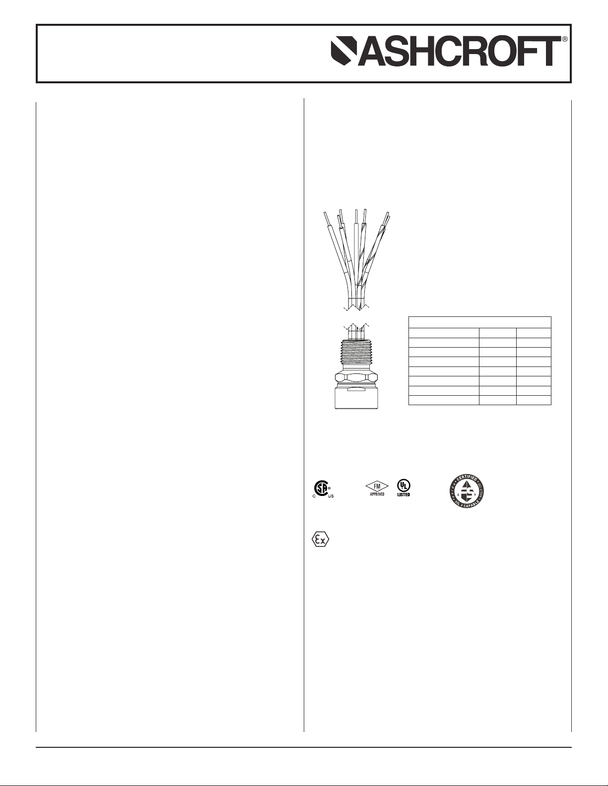
WIRE COLOR/FUNCTION
WIRE COLOR SWITCH FUNCTION
RED SW1 NC
WHITE SW1 C
BLUE SW1 NO
WHITE/BLACK SW2 C
RED/BLACK SW2 NC
BLUE/BLACK SW2 NO
GREEN – Ground
Safety Manual and SIL Certificate, CRN available on
www.ashcroft.com
APPROVALS:
FACTORY
SEALED
CLASS I DIV 1 GROUPS A, B, C, & D
CLASS II DIV 1GROUPS E, F, & G
Sira 13ATEX1123X
IECEx
CSA 13.0015X
SI L 3 CAP ABL E
II 2GD
Ex d IIC T6/T5 Gb
Ex tb IIIC T85°C/T100°C Db
Ta or Tp = -20/-40°C* to +74/89°C**
*Low ambient temperature is dependent upon Switch Code,
Pressure Range, Material Code and Temperature Code per
table in description. Only one low temperature is shown as
they are the same for both T6 and T5 Codes.
**High ambient temperature is dependent upon Switch Code,
and Temperature Code per table in description. Both high
temperature limits are listed as they may be different for the
T6 and T5 Codes. They are separated by a “/” as shown.
© 2016 Ashcroft Inc., 250 East Main Street, Stratford, CT 06614-5145, USA, Tel: 203-378-8281, Fax: 203-385-0499, www.ashcroft.com
All sales subject to standard terms and conditions of sale.
I&M009-10046 (250-2966) Rev. 03/16
 Loading...