

Page 1
A4 INTRINSICALLY SAFE &
.50
3.065
4.45
.885
1.06
DIA.
1.06 Hex.
Common For All
Pressure Fittings
.887˝
4.78˝
3.065˝
.675˝
1.06˝
DIA.
(22.5)
(121)
(78)
(17)
(27)
.887˝
4.78˝
3.065˝
.885˝
1.06˝ (27) Hex.
Common For All
Pressure Fittings
(22)
(78)
(121)
(22.5)
1.06˝
DIA.
(27)
NON-INCENDIVE RATED
PRESSURE TRANSMITTER
INSTRUCTION SHEET
WARNING! READ
BEFORE INSTALLATION
1. GENERAL:
A failure resulting in injury or damage
may be caused by excessive overpressure, excessive vibration or
pressure pulsation, excessive instrument temperature, corrosion of the
pressure containing parts, or other
misuse. Consult Ashcroft Inc.,
Stratford, Connecticut, USA before
installing if there are any questions
or concerns.
2. OVERPRESSURE:
Pressure spikes in excess of the rated
overpressure capability of the transducer
may cause irreversible electrical
and/or mechanical damage to the
pressure measuring and containing
elements.
Fluid hammer and surges can destroy
any pressure transducer and must
always be avoided. A pressure snubber
should be installed to eliminate the
damaging hammer effects. Fluid hammer occurs when a liquid flow is suddenly stopped, as with quick closing
solenoid valves. Surges occur when
flow is suddenly begun, as when a
ump is turned on at full power or a
p
valve is quickly opened.
iquid surges are particularly damaging
L
to pressure transducers if the pipe is
originally empty. To avoid damaging
surges, fluid lines should remain full (if
possible), pumps should be brought up
to power slowly, and valves opened
slowly. To avoid damage from both fluid
hammer and surges, a surge chamber
should be installed.
Symptoms of fluid hammer and surge's
damaging effects:
• Pressure transducer exhibits an output at zero pressure (large zero offset).
• Pressure transducer output remains
constant regardless of pressure
• In severe cases, there will be no output.
FREEZING:
Prohibit freezing of media in pressure
port. Unit should be drained (mount in
vertical position with electrical termination upward) to prevent possible overpressure damage from frozen media.
3. STATIC ELECTRICAL CHARGES:
Any electrical device may be susceptible to damage when exposed to static
electrical charges. To avoid damage to
the transducer observe the following:
• Operator/installer should follow the
roper ESD (electrostatic discharge)
p
protection procedures before handling
the pressure transducer.
• Ground the body of the transducer
BEFORE making any electrical
connections
• When disconnecting, remove the
ground LAST!
Note: The shield and drain wire in the
cable (if supplied) is not connected to
the transducer body, and is not a suitable ground.
4. HAZARDOUS AREA SPECIFIC GUIDELINES
1. Do not open unit when energized.
2. Do not diconnect equipment unless
area is known to be non-hazardous.
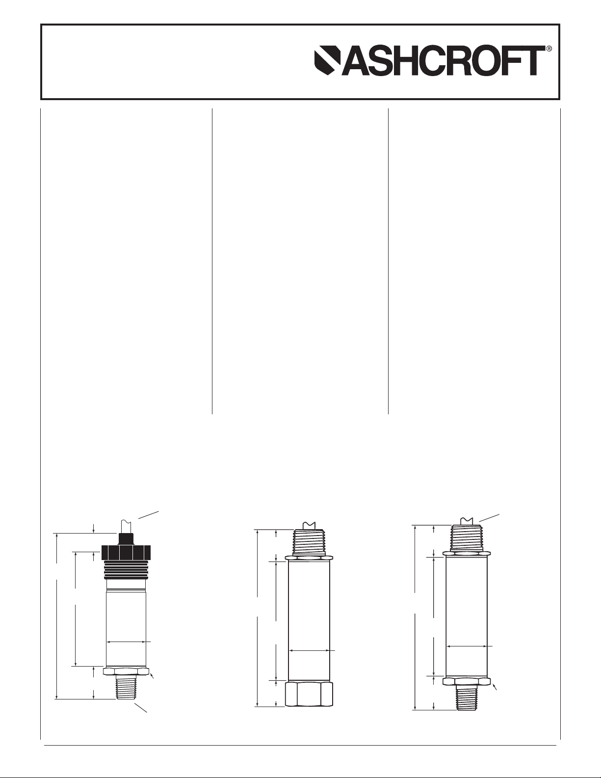
Ashcroft®A4 Pressure Transmitter, Typical Dimensions and Construction*
Enclosure Option “S” Enclosure Option “W”
Cable style
electrical
termination
© 2011 Ashcroft Inc. All rights reser ved. 250 East Main Street, Stratford, CT 06614 USA Tel: 203-378-8281, Fax: 203-385-0402 www.ashcroft.com
All sales subject to standard terms and conditions of sale.
Threaded Male Process Connection
I&M011-10166-A4. Rev. 12/12
*
Dimensions and construction details may vary based on product specified.
Conduit style
electrical
termination
Page 2
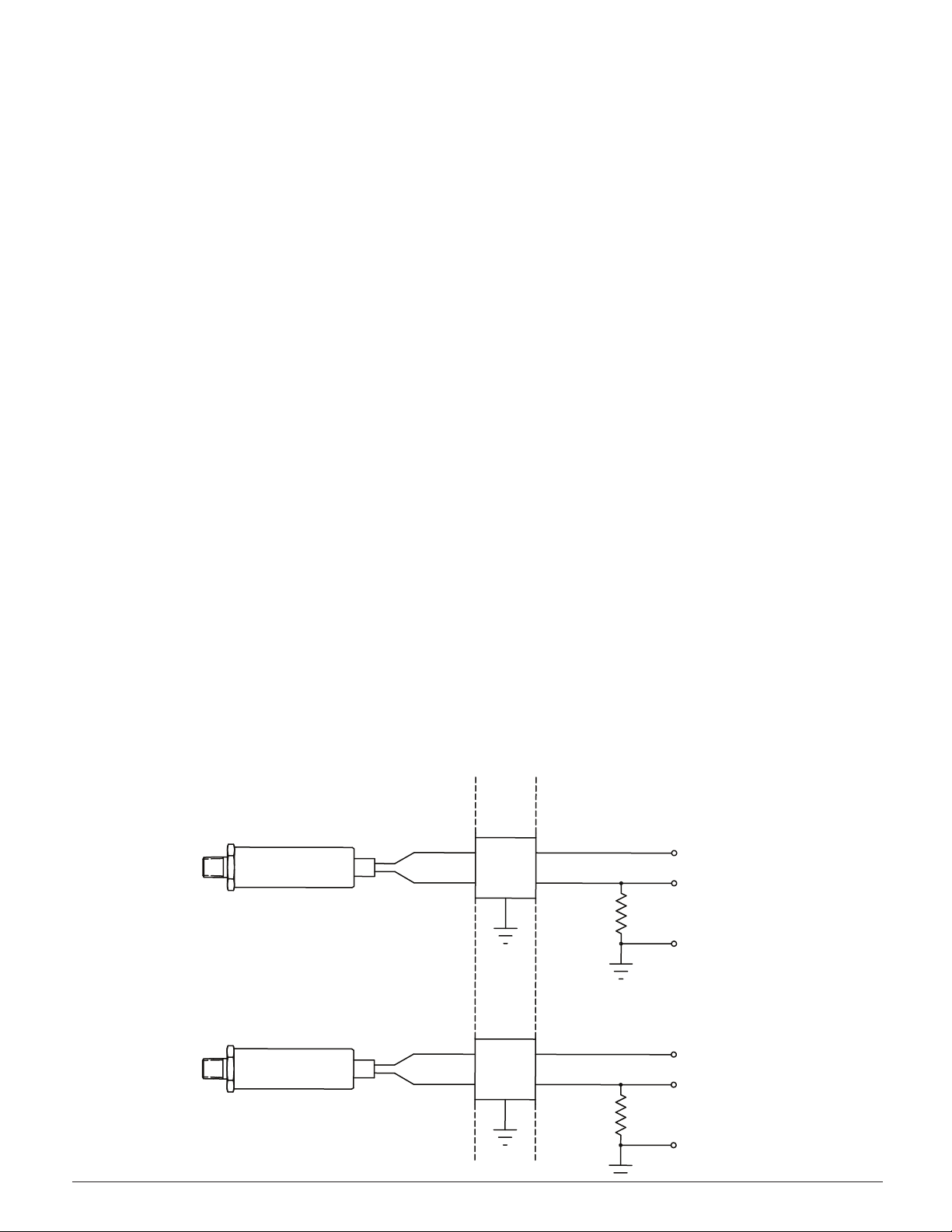
HAZARDOUS (CLASSIFIED) AREA
CLASS I, DIVISION 1 & 2,
GROUPS A, B, C, & D;
CLASS II, DIVISION 1 & 2,
GROUPS E, F & G, CLASS III
NON-HAZARDOUS
(UNCLASSIFIED) AREA
BARRIER
BARRIER
V+
V–
MODEL A2X & A4 SERIES
4-20MA TRANSMITTER
R LOAD
250 OHM
TYP.
R LOAD
250 OHM
TYP.
MODEL A2X & A4 SERIES
4-20MA TRANSMITTER
V+
V–
+24 VDC TYP.
+
–24 VDC TYP.
–
V OUT
(1-5 V TYP.)
V OUT
(1-5 V TYP.)
4.3 FM INSTALLATION GUIDELINES
INSTALLATION FOR FM
INTRINSICALLY SAFE CLASS 1, GROUPS A, B, C & D &
LASS ll, GROUPS E, F & G &
C
NSTALLATION NOTES≥
Voc OR Vt ≤30VDC
Isc OR It ≤100mA
Ca≥ 0.053uF + Ccable
La ≥ 0.364uH + Lcable
1. THE INTRINSIC SAFETY ENTITY CONCEPT ALLOWS THE INTERCONNECTION OF TWO INTRINSICALLY SAFE DEVICES FM
PPROVED WITH ENTITY PARAMETERS NOT SPECIFICALLY
A
EXAMINED IN COMBINATION AS A SYSTEM WHEN: Uo OR Voc
OR V≤t Vmax, Io OR Isc OR≤ It Imax, Ca OR Co ≥ Ci + Ccable, La
OR ≥Lo Li +Lcable≤, Po Pi.
2. THE NONINCENDIVE FIELD WIRING CONCEPT ALLOWS INTERCONNECTION OF NONINCENDING FIELD WIRING APPARATUS
WITH ASSOCIATED NONINCENDIVE FIELD APPARATUS USING
ANY OF THE WIRING METHODS PERMITTED FOR NON3HAZARDOUS (UNCLASSIFIED) LOCATIONS WHEN: Uo OR Voc OR Vt
Vmax, Io OR Isc OR It Imax, Ca OR Co + Ccable, La OR Lo Li
+Lcable, Po Pi.
3. FOR DIVISION 1 INSTALLATIONS, THE CONFIGURATION OF
ASSOCIATED APPARATUS SHALL BE FM APPROVED UNDER
ENTITY CONCEPT.
4. FOR DIVISION 2 INSTALLATIONS USING NONINCENDIVE FIELD
WIRING CONCEPTS THE ASSOCIATED APPARATUS SHALL BE FM
APPROVED UNDER THE ENTITY CONCEPT OR NONINCENDIVE
FIELD WIRING CONCEPT.
CLASS lll
. FOR DIVISION 2 INSTALLATIONS THE ASSOCIATED APPARATUS
5
IS NOT REQUIRED TO BE FM APPROVED UNDER ENTITY CONCEPT OR NONINCENDIVE FIELD WIRING CONCEPT IF THE
A2X(4-20mA) & A4 SERIES PRESSURE TRANSDUCER IS
INSTALLED IN ACCORDANCE WITH THE NATIONAL ELECTRICAL
CODE (ANSI/NFPA 70) FOR DIVISION 2 WIRING METHODS
EXCLUDING NONINCENDIVE FIELD WIRING.
. CONTROL EQUIPMENT CONNECTED TO THE ASSOCIATED APPA-
6
RATUS SHALL NOT USE OR GENERATE MORE THAN 250VRMS
OR VDC.
7. DIVISION 1 INSTALLATIONS SHOULD BE IN ACCORDANCE WITH
ANSI/ISA RP12.06.01, ``INSTALLATION OF INTRINSICALLY SAFE
SYSTEMS FOR HAZARDOUS (CLASSIFIED) LOCATIONS'' AND
THE NATIONAL ELECTRICAL CODE (ANSI/NFPA 70).
8. ASSOCIATED APPARATUS MANUFACTURERS INSTALLATION
DRAWING SHALL BE FOLLOWED WHEN INSTALLING THIS
EQUIPMENT.
9. RUN SHIELDED INTERCONNECTION CABLE WITH SHIELD CONNECTED TO FM APPROVED ASSOCIATED APPARATUS GROUND.
10. WARNING – DO NOT OPEN WHEN ENERGIZED.
11. WARNING – DO NOT DISCONNECT EQUIPMENT UNLESS AREA IS
KNOWN TO BE NON-HAZARDOUS.
© 2011 Ashcroft Inc. All rights reser ved. 250 East Main Street, Stratford, CT 06614 USA Tel: 203-378-8281, Fax: 203-385-0402 www.ashcroft.com
All sales subject to standard terms and conditions of sale.
I&M011-10166-A4. Rev. 12/12
Page 3

HAZARDOUS (CLASSIFIED) AREA
CLASS I, DIVISION 1 & 2,
GROUPS A, B, C, & D;
CLASS II, DIVISION 1 & 2,
GROUPS E, F & G, CLASS III
NON-HAZARDOUS
(UNCLASSIFIED) AREA
BARRIER
BARRIER
V+
V–
MODEL A2X & A4 SERIES
4-20MA TRANSMITTER
R LOAD
250 OHM
TYP.
R LOAD
250 OHM
TYP.
MODEL A2X & A4 SERIES
4-20MA TRANSMITTER
V+
V–
+24 VDC TYP.
+
–24 VDC TYP.
–
V OUT
(1-5 V TYP.)
V OUT
(1-5 V TYP.)
4.4 CSA INSTALLATION GUIDELINES
INSTALLATION FOR CSA
NTRINSICALLY SAFE CLASS 1, GROUPS A, B, C & D &
I
CLASS ll, GROUPS E, F & G &
CLASS llI
INSTALLATION NOTES:
Vmax 30VDC
Imax 100mA
Ci = 0.053uF
Li = 0.364uH
1. THE INTRINSIC SAFETY ENTITY CONCEPT ALLOWS THE INTERONNECTION OF TWO INTRINSICALLY SAFE DEVICES CSA CER-
C
TIFIED WITH ENTITY PARAMETERS NOT SPECIFICALLY EXAMINED IN COMBINATION AS A SYSTEM WHEN: Uo OR Voc Vmax,
Io OR Isc Imax, Ca OR Co Ci + Ccable, La OR Lo Li +Lcable, Po
Pi.
2. THE NONINCENDIVE FIELD WIRING CONCEPT ALLOWS INTER-
CONNECTION OF NONINCENDING FIELD WIRING APPARATUS
WITH ASSOCIATED NONINCENDIVE FIELD APPARATUS USING
ANY OF THE WIRING METHODS PERMITTED FOR NON3HAZARDOUS (UNCLASSIFIED) LOCATIONS WHEN:
Uo OR Voc Vmax, Io OR Isc Imax,
Ca OR Co + Ccable, La OR Lo Li +Lcable, Po Pi.
3. FOR DIVISION 1 INSTALLATIONS, THE CONFIGURATION OF
ASSOCIATED APPARATUS SHALL BE CSA CERTIFIED UNDER
ENTITY CONCEPT.
4. FOR DIVISION 2 INSTALLATIONS USING NONINCENDIVE FIELD
WIRING CONCEPTS THE ASSOCIATED APPARATUS SHALL BE
CSA CERTIFIED UNDER THE ENTITY CONCEPT OR NONINCEN-
IVE FIELD WIRING CONCEPT.
D
5. FOR DIVISION 2 INSTALLATIONS THE ASSOCIATED APPARATUS
IS NOT REQUIRED TO BE CSA CERTIFIED UNDER ENTITY CONCEPT OR NONINCENDIVE FIELD WIRING CONCEPT IF THEA2X
(4-20mA) & A4 SERIES PRESSURE TRANSDUCER IS INSTALLED
IN ACCORDANCE WITH THE CANADIAN ELECTRICAL CODE (CEC,
CAN/CSA3C22.1) FOR DIVISION 2 WIRING METHODS EXCLUD-
NG NONINCENDIVE FIELD WIRING.
I
6. CONTROL EQUIPMENT CONNECTED TO THE ASSOCIATED APPARATUS SHALL NOT USE OR GENERATE MORE THAN 250VRMS
OR VDC.
7. ASSOCIATED APPARATUS MANUFACTURERS INSTALLATION
DRAWING SHALL BE FOLLOWED WHEN INSTALLING THIS
EQUIPMENT.
8. RUN SHIELDED INTERCONNECTION CABLE WITH SHIELD CONNECTED TO FM APPROVED ASSOCIATED APPARATUS GROUND.
9. WARNING – SUBSTITUTION OF COMPONENETS MAY IMPAIR
INTRINSIC SAFETY
10. WARNING – TO PREVENT IGNITION OF FLAMMABLE OR COMBUSTIBLE ATMOSPHERES, DISCONNECT POWER BEFORE
SERVICING.
© 2011 Ashcroft Inc. All rights reser ved. 250 East Main Street, Stratford, CT 06614 USA Tel: 203-378-8281, Fax: 203-385-0402 www.ashcroft.com
All sales subject to standard terms and conditions of sale.
I&M011-10166-A4. Rev. 12/12
Page 4

A4 INTRINSICALLY SAFE &
+
+
–
POWER
SUPPLY
(+)
(–)
T
RANSDUCER
–
V+
V–
PIN 1
PIN 2
4-20mA
METER
OR OTHER DEVICE
.062
Z S
Z S
“Z” and “S” pots
NON-INCENDIVE RATED
PRESSURE TRANSMITTER
INSTRUCTION SHEET
Mounting
The A4 transmitter requires no special
mounting hardware, and can be mounted
in any plane with negligible position error.
Although the unit can withstand normal
vibration without damage or significant
output effects, it is always good practice
to mount the transducer where there is
minimum vibration.
For units with NPT type pressure fittings
apply Teflon
®
tape or an equivalent
sealant to the threads before installing.
When tightening, apply a wrench to the
hex wrench flats located just above the
pressure fitting. DO NOT tighten by using
a pipe wrench on the housing.
Power Supply
Power Supply Voltage
Output Signal Min Max
4-20mA* 12V** 30V
* Refer to Ashcroft drawing #825A022 for
supply voltage and load limit.
** The minimum voltage at the terminals is
12Vdc. However, the minimum supply
voltage should be calculated using the
following graph and formula.
Loop Supply Voltage vs. Loop Resistance
1000
30 Vdc max for
800
600
400
200
Loop Resistance (Ohms)
Vmin = 12V+ (.022A x RL) (includes a 10% safety factor)
RL = RS + RW
RL = Loop Resistance (ohms)
RS = Sense Resistance (ohms)
RW = Wire Resistance (ohms)
Intrinsically Safe
Installations
0
10
Loop Supply Voltage (Vdc)
Operating
Region
20 30
Noise
For minimum noise susceptibility, avoid
running the transducer’s cable in a conduit that contains high current AC power
cables. Where possible avoid running
the cable near inductive equipment.
Shielded Cable
Units with shielded cable electrical termi-
ation, connect the drain wire to the
n
guard terminal on the read out device or
measuring instrument, if available. In all
other cases connect to the ground or to
the power supply negative terminal.
Vent Tube (Cable Termination Only)
The cable has a clear Teflon
®
vent tube
required at pressure ranges below 500
psi to provide atmospheric reference.
The open end should be placed in a
dry area.
A4 Wiring Diagrams
A4 transducer has internal transient
protection: for safety, limit line-toground voltage to 36 Vdc max.
Zero and Span Adjustment
Instructions below apply to the particular
configurations noted. While Zero adjustment is not normally necessary, it may be
desirable to trim out any offset in the system. However, proper Span calibration
requires a pressure standard three to five
times more accurate than the accuracy of
the transducer, and there may also be
interaction of Span on Zero.
A4 configurations with enclosure “S”
offer Zero and Span potentiometer
ccess.
a
Access to “Z” and “S” pots via the top
(electrical termination end) of the unit is
tandard on all “S” enclosure units with 4-
s
20mA output. Access is gained by removing the black threaded cap, once removed
ou will see the pots indicated by “Z” and
y
“S” respectively as shown below. Using a
small trim pot tool, you can adjust zero
±10% of full scale and span ±10% of
full scale.
Recalibration Instructions:
1. Apply 0% full scale pressure.
2. Adjust the output using the zero adjust
trim pot.
3. Apply 100% full scale pressure.
4. Adjust the output using the span adjustment trim pot.
5. Repeat steps 1 through 4 as necessary.
HAZARDOUS AREA CERTIFICATIONS
Intrinsically Safe (applies to 4-20mA) FM/CSA:
Intrinsic Safety: Class I, II and III Div.1 and 2,
Non-Incendive: Class I, II and III Div.1 and 2,
Groups A, B, C, D, F and G per
entity requirements see Ashcroft
drawing # 825A022
Groups A, B, C, D, F and G, no
barriers needed
© 2011 Ashcroft Inc. All rights reser ved. 250 East Main Street, Stratford, CT 06614 USA Tel: 203-378-8281, Fax: 203-385-0402 www.ashcroft.com
All sales subject to standard terms and conditions of sale.
I&M011-10166-A4. Rev. 12/12
Page 5

A4 INTRINSICALLY SAFE &
.600
(4) PIN BENDIX STYLE
ELECTRICAL TERMINATION
SHELL SIZE 8
(B4), (H1), (L1), (P2)
PROCESS
FITTING
(REF.)
1.062
1.000
.830
PIGTAIL
ELECTRICAL TERMINATION
CONDUIT - 1/2 NPT MALE
(C1), (P7)
ELECTRICAL TERMINATIONS FOR
WELDED HOUSINGS ONLY
1.062
C
D
B
A
.71
M12
EL E CT RI CA L TE RM IN AT IO N
(EW), (E0), (E1), (E2)
1.320
.18
.64
DIN 43650-A
EL E CT RI CA L TE RM IN AT IO N
(CD), (DN), (D0), (D1), (D2)
1.320
.65
(4) PIN BENDIX STYLE
EL E CT RI CA L TE RM IN AT IO N
SHELL SIZE 8
(B4), (H1), (L1), (P2)
1.320
PIGTAIL
EL E CT RI CA L TE RM IN AT IO N
PLASTIC MOLDED
(F2), (P1)
1.320
.50
C
D
B
A
3
4
2
1
Key
2
1
3
Gnd.
NON-INCENDIVE RATED
PRESSURE TRANSMITTER
INSTRUCTION SHEET
oltage Current
in #
P
V
utput Output
O
A (+) Power (+) Power
B (+) Output None
C Field Gnd. Field Gnd.
D (-) Power (-) Power
ire Voltage Current
W
olor Output Output
C
Red (+) Power (+) Power
White (+) Output None
Black (-) Power (-) Power
Green Field Grd. Field Grd.
Bare Drain Wire Drain Wire
Pin Voltage Current Mating
No. Output Output Cable Color
1 (+) Power (+) Power Red
2 (+) Output None White
3 Field Gnd. Field Gnd. Green
4 (-) Power (-) Power Black
Pin Voltage Current Mating
No. Output Output Cable Color
1 (+) Power (+) Power Red
2 (-) Power (-) Power Black
3 (+) Output None White
GND Field Gnd. Field Gnd. Green
Pin Voltage Current Mating
No. Output Output Cable Color
A (+) Power (+) Power Red
B (+) Output None White
C Field Gnd. Field Gnd. Geen
D (-) Power (-) Power Black
© 2011 Ashcroft Inc. All rights reser ved. 250 East Main Street, Stratford, CT 06614 USA Tel: 203-378-8281, Fax: 203-385-0402 www.ashcroft.com
All sales subject to standard terms and conditions of sale.
I&M011-10166-A4. Rev. 12/12
Wire Voltage Current
Color Output Output
Red (+) Power (+) Power
White (+) Output None
Black (-) Power (-) Power
Green Field Gnd. Field Gnd.
Bare Drain Wire Drain Wire
Page 6

Visit our web site www.ashcroft.com
All sales subject to standard terms and conditions of sale. I&M011-10166-A4. Rev. 10/12
Ashcroft Inc.
250 East Main Street
Stratford, CT 06614-5145 USA
Tel: 203-378-8281 • Fax: 203-385-0402
email: info@ashcroft.com
www.ashcroft.com
 Loading...