

Page 1
Type 80 Wafer and Type 81
Bolt-Thru Isolation Rings
Installation and Maintenance
Instructions
© 2014 Ashcroft Inc., 250 East Main Street, Stratford CT 06614 USA Tel: 203-378-8281 • Fax: 203-385-0602 www.ashcroft.com
All sales subject to standard terms and conditions of sale. I&M008-10223 06/14
1
Page 2

© 2014 Ashcroft Inc., 250 East Main Street, Stratford CT 06614 USA Tel: 203-378-8281 • Fax: 203-385-0602 www.ashcroft.com
All sales subject to standard terms and conditions of sale. I&M008-10223 06/14
2
Page 3

TABLE OF CONTENTS
1. CAUTION
2. OVERVIEW
3. SPECIFICATIONS
4. DIMENSIONAL DRAWINGS
5. PRODUCT INSTALLATION
6. ASSEMBLY REMOVAL
7. PRODUCT MAINTENANCE / IN-SERVICE REPLACEMENT
8. STORAGE
1 - CAUTION
2 - OVERVIEW
3 - PRODUCT
SPECIFICATIONS
CAUTION
WARNING! READ PRIOR TO PRODUCT INSTALLATION AND/OR MAINTENANCE
GENERAL:
Use proper safety equipment and procedures when handling product. Failures causing injury and/or
damage may be the result of excessive process overpressures / temperatures, improper material selection
(chemical compatibility) or other potential misuse.
OVERVIEW
Isolation rings are designed to protect measuring devices, e.g. pressure gauges, switches, and transducers,
from direct contact with the process media. Using a 360-degree flexible liner that eliminates the potential for
clogging and/or fouling, while transmitting pressure hydraulically to the instrument. Offered in two styles,
Type 80 (Wafer) and Type 81 (Bolt-thru), each is mounted between customer-supplied flanges of process
piping; available in nominal pipe sizes from 2˝ to 20˝ and 2˝ to 10˝, respectively.
PRODUCT SPECIFICATIONS
Type/Size:
Type 80 Wafer: 2˝ to 20˝
Type 81 Bolt-Thru: 2˝ to 10˝
Liner Materials: Buna-N, Teflon
®
, EPDM, Natural Rubber, Viton
®
Liner Process Temeperature Limits: Buna-N –30/225°F
®
Teflon
Viton
®
–15/350°F
–15/350°F
Natural Rubber –30/225°F
EPDM –40/300°F
Flange Materials: 316L SS, Carbon Steel
Flange (Type 81 Bolt-Thru only): ANSI/ASME Class 150 / 300 (Type 80 wafer applicable in both
150 and 300 class)
Body: 316L SS, Carbon Steel
Instrument Connection Size: ¼, ½ Female NPT
Fill Fluid: Glycerin, Silicone (10 CST), Silicone (5 CST), Halocarbon.
AVAILABLE PRODUCT OPTIONS
Safe Quick Release Instrument Removal Option: (SQR)
• All Welded Assembly (XDU) – Not available with Safe Quick Release (SQR) and/or Needle Valve
• Retrofit Flange (XIR)
• Wired Stainless Steel Tag (XNH)
• Calibration Chart (XC4) – Measuring instrument attached
Consult factory for additional options
3
Page 4
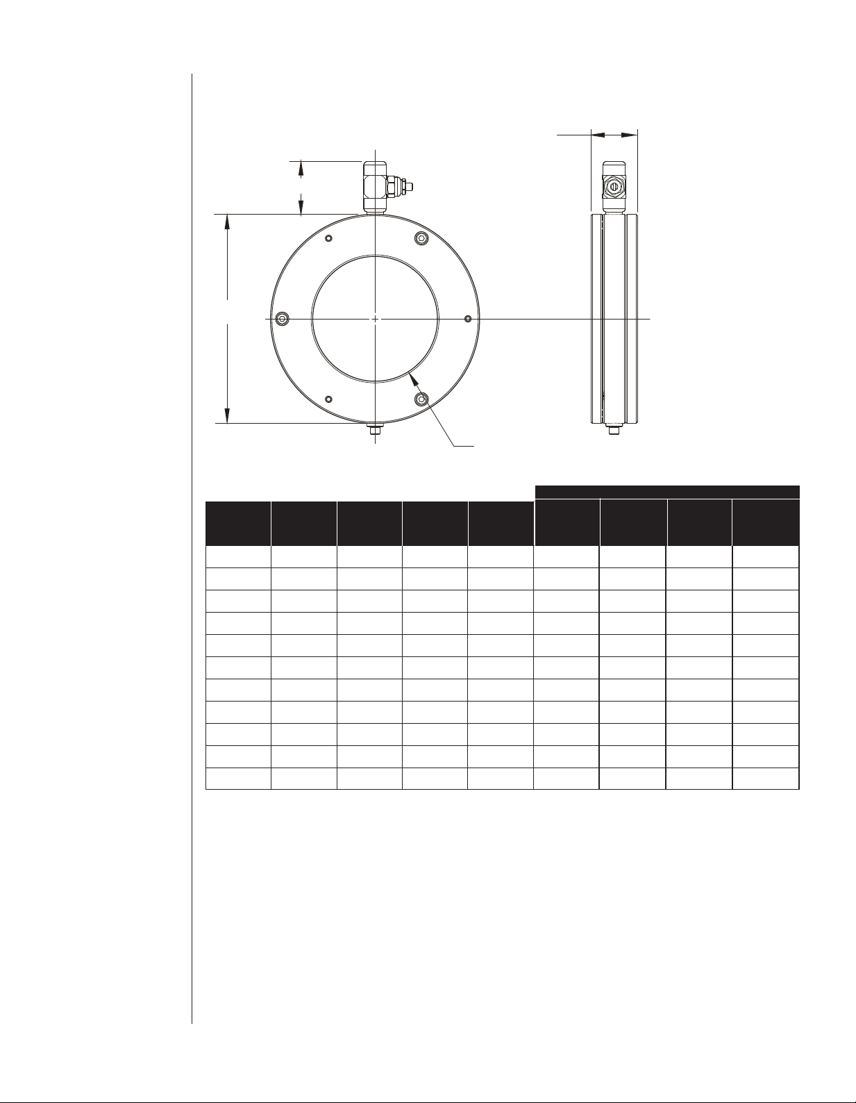
DRAWINGS
Ø
ID
Ø
OD
H
W
DIMENSION DRAWINGS 4 - DIMENSION
Type 80 Wafer Isolation Ring
Nominal
Pipe
Size
Inner
Diameter
(ID)
2˝ 2.07 4.00 2.13 2.00 1.89 2.04 1.70 4.0
3˝ 3.07 5.25 2.13 2.00 1.89 2.04 1.70 6.3
4˝ 4.03 6.75 2.13 1.50 1.89 2.04 1.70 8.0
6˝ 6.07 8.63 2.25 1.50 1.89 2.67 2.32 10.2
8˝ 7.98 10.88 2.50 1.50 2.39 2.67 2.32 14.9
10˝ 10.02 13.25 2.75 1.50 2.39 2.67 2.32 21.3
12˝ 12.00 16.00 3.00 1.75 2.39 2.67 2.32
14˝ 13.25 17.63 3.00 1.75 2.89 3.17 2.82
16˝ 15.25 20.13 3.00 1.75 2.89 3.17 2.82 61.8
18˝ 17.25 21.50 3.00 1.75 2.89 3.67 3.32
20˝ 19.25 23.75 3.00 1.75 2.89 3.67 3.32 68.6
All dimensions shown in inches.
Outer
Diameter
(OD)
Retrofit
Width
(XIR)
Width
(W)
Instrument Removal (H)
Safe
None Quick
Release
Needle Weight
Valve Lbs.
39.1
47.8
58.0
4
Page 5

DRAWINGS
Ø
BC
Ø
ID
H
Ø
BD
W
Ø
OD
DIMENSION DRAWINGS (cont.)4 - DIMENSION
Type 81 Bolt-Thru Isolation Ring
ANSI Nominal Inner Outer Bolt Bolt No. Of
ASME Pipe Diameter Diameter Width Circle Diameter Bolt
Class Size (ID) (OD) (W) (BC) (BD) Holes
2˝ 2.07 6.00 2.00 4.75 0.75 4– 2.04 1.70 12.0
3˝ 3.07 7.50 2.00 6.00 0.75 4– 2.04 1.70 18.4
150 4˝ 4.03 9.00 1.50 7.50 0.75 8– 2.04 1.70 18.6
6˝ 6.07 11.00 1.50 9.50 0.88 8– 2.04 1.70 23.9
8˝ 7.98 13.50 1.50 11.75 0.88 8– 2.04 1.70 34.5
10˝ 10.02 16.00 1.50 14.25 1.00 12 – 2.04 1.70 44.5
2˝ 2.07 6.50 2.00 5.00 0.75 8– 2.04 1.70 13.8
3˝ 3.07 8.25 2.00 6.62 0.88 8– 2.04 1.70 22.0
300 4˝ 4.03 10.00 1.50 7.88 0.88 8– 2.04 1.70 24.5
6˝ 6.07 12.50 1.50 10.62 0.88 12 – 2.04 1.70 34.9
8˝ 7.98 15.00 1.50 13.00 1.00 12 – 2.04 1.70 47.1
10˝ 10.02 17.50 1.50 15.25 1.13 16 – 2.04 1.70 58.8
Instrument Removal (H)
None
Safe Quick Needle Weight
Release (SQR) Valve Lbs.
5
Page 6

5 - PRODUCT
INSTALLATION
PRODUCT INSTALLATION
MATERIAL COMPATIBILITY: Wetted material selection is critical to the product’s life cycle and reliability.
In order to ensure proper material selection, elements to consider are:
• Process Fluid
• Process Fluid Concentration (%)
• Process Pressure and Temperature
• Assembly Fill Fluid – check compatibility
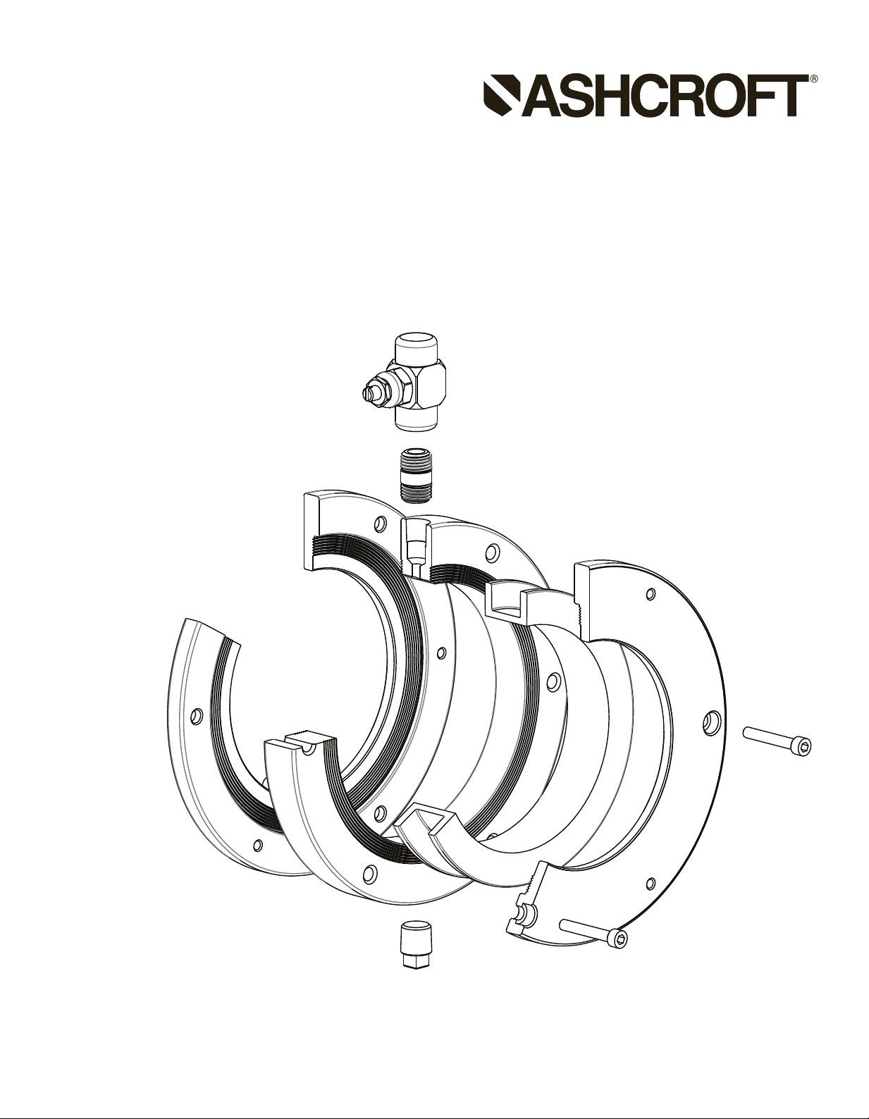
Isolation Ring Styles:
Type 80 Wafer:
(Exploded View)
Gaskets, nuts and bolts provided by USER
6
Page 7

Type 80 Wafer
(Installed View)
Type 81 Bolt-Thru
(Exploded View)
Gaskets, nuts and bolts provided by USER
7
Page 8

Type 81 Bolt-Thru
(Installed View)
Prior to installation, please follow the recommended manufacturer procedure:
A. Confirm process has been shut down with process pressure relieved and piping drained.
B. Provide pipe flange gasketing, mounting bolts, lockwashers and nuts (not supplied by Ashcroft).
Step 1: Isolation ring and flange gaskets should be centered between process piping flanges.
For Type 80 Wafer: Assembly is installed by placing centering gages (shims) on the two bottom-most flange
bolts; these are supplied by Ashcroft with each isolation ring assembly. Refer to the following table for centering gage size based on flange class rating. Note: Centering gauges may be removed afterwards by
breaking.
ANSI/ASME
CLASS RATING GAGE SIZE
NPS
CENTERING
Class 150 All Sizes 1/8˝
2˝ 1/4˝
3˝ 3/8˝
4˝ 1/4˝
6˝ 11/16˝
8˝ 11/16˝
Class 300 10˝ 9/16˝
12˝ 3/8˝
14˝ 13/16˝
16˝ 5/8˝
18˝ 1-1/16˝
20˝ 1-1/16˝
Step 2: Position Type 80 Wafer isolation ring with centering-gages or Type 81 Bolt-Thru using two bottommost bolts through unit and process flanges. Take care to ensure that any attached instruments are directed
in a vertical (upward) configuration, while measuring devices (e.g. gauge, switch, transducer) are also positioned between the two upper-most flange bolts to prevent obstruction with the process piping.
8
Page 9

Step 3: Tighten the piping flange bolts to the locking nuts / washers on the opposite flange. Each should be
P
IPE FLANGE
(NPS 4", CLASS 300 SHOWN)
C
ENTERING GAGE
ISOLATION RING
(
NPS 4", TYPE 80 SHOWN)
FLANGE BOLT
INSTRUMENT REMOVAL DEVICE
(NEEDLE VALVE SHOWN)
ASSEMBLY FLANGE
ASSEMBLY SCREW
FLEXIBLE LINER
SENSING FLUID
FILL PORT
CENTER BODY
FLANGE GASKET
FLANGE BOLT
tightened by cross-bolting with the proper torque based as described in ASME PCC-1 on NPS, ANSI/ASME
Class rating, and gasketing used.
6- ASSEMBLY REMOVAL
ASSEMBLY REMOVAL
IMPORTANT: In the event the assembly needs to be removed from process, follow the manufacturer’s rec-
ommended procedure to prevent possible injury and/or damage.
A. Confirm process has been shut down with process pressure relieved and piping drained, cleaned and
dried before installation and/or removal of product assembly.
B. Ensure the assembly is supported prior to removal of bolts/flanges.
9
Page 10

7 - PRODUCT
MAINTENANCE /
IN-SERVICE
REPLACEMENT
8 - STORAGE
C. Loosen flange bolts securing the isolation ring assembly to the process pipe flange.
D. Upon separation of pipe flanges, remove assembly and flange gaskets from the piping.
In the event only instrument removal is required, use a wrench to unthread the instrument. Use container to
catch the fill fluid when draining from the isolation ring.
PRODUCT MAINTENANCE / IN-SERVICE REPLACEMENT
The following provides the user with th necessary instructions to service this product. This will allow the
ustomer to perform routine maintenance that may involve in-service instrument replacement.
c
IN-SERVICE INSTRUMENT REMOVAL / REPLACEMENT (Dependent upon type of assembly connection
listed below)
1) Direct Mount Instrument Removal: Measuring instrument should never be removed from the isolation
ring while in service. For instrument replacement, complete removal of the isolation ring assembly from
ervice is required.
s
2) Needle Valve Instrument Removal Option:
a) Shut down process and fully vent/relieve pressure to the assembly. While it is possible that pressure
may be retained in the process when the instrument is removed, it is imperative that the process pressure MUST be at Zero (0 psi) when reinstalling the replacement instrument.
IMPORTANT: Residual pressure may cause potential injury/damage, and replacing an instrument with
residual pressure could result in fill fluid imbalance, thereby causing accuracy errors.
b) Using a flathead screwdriver, turn the adjustment on the needle valve until fully closed (clockwise).
c) Secure the needle valve body using a ¾˝ wrench, and remove the attached measuring instrument (e.g.
gauge, switch, transducer) with a second wrench applied to the instrument’s wrench flats.
d) Position and secure the measuring instrument so that the pressure port is facing upwards. Then utilizing
an ordinary syringe, fill the internal cavity of the process connection with compatible fill fluid. Place finger
on the port and tilt side-to-side to dislodge any trapped air. Continue filling until air bubbles no longer
appear. Note: Improper fill can result in accuracy errors or damage to the flexible isolation ring liner.
Highly viscous fill fluids may require 10 to 15 minutes until air has been completely dislodged.
e) Apply Teflon tape or sealant to instrument fitting while unit is still upside down and place aside while
retaining this position.
f) Pour fill fluid into instrument until fill fluid is overflowing.
g) Using the flathead screwdriver, open the needle valve. Fill needle valve port until fluid is overflowing.
h) Once steps e, f and g have been completed, take the filled measuring instrument and quickly “flip” over
to install (thread) into the top port of the needle valve. This needs to be performed to lose as little fill
fluid as possible.
i) Secure both instruments utilizing the two wrenches previously used for disassembly.
3) Safe Quick Release (SQR) Option: This option provides the end-user with a flexible approach to
remove/replace an existing instrument once the isolation ring has been installed. Prior to removal, it will
be necessary to obtain a pre-filled instrument to allow continued operation and limit downtime. RECORD
the product model number and pressure at which the instrument has been removed; this is important as
it ensures that an exact replacement is “pre-charged” at the factory to retain accuracy. Safe Quick
Release (SQR) removal procedure is as follows:
a) Ensure process pressure has been relieved to the proper intended removal pressure of <300 psi.
Recommended removal/replacement of product is Zero (0 psi).
b) Twist the instrument so that the coupling sleeve-relief lines up with the sleeve-lock key.
c) While holding the instrument securely, pull sleeve downward to disengage coupling.
d) Place newly “pre-charged” instrument on the coupling and pressure downward to engage the coupling.
STORAGE
Store in a cool, dry area.
10
Page 11

11
Page 12

12
Ashcroft Inc.,
250 East Main Street
Stratford, CT 06614-5145
U.S.A.
Tel: 203-378-8281
Fax: 203-385-0408 (Domestic)
Fax: 203-385-0357 (International)
email: info@ashcroft.com
www.ashcroft.com
I&M008-10223-6/14
Visit our web site www.ashcroft.com
 Loading...