

Page 1
TYPE 1279 & 1379 SOLID FRONT
DURAGAUGE PRESSURE GAUGE
LIQUID FILL CONVERSION
INSTRUCTIONS
© 2007 Ashcroft Inc., 250 East Main Street, Stratford, CT 06614 USA, Tel: 203-378-8281, Fax 203-385-0402 www.ashcroft.com
All sales subject to standard terms and conditions of sale. All rights reserved. I&M008-10090 (84B276) Rev 5/05 P5/07
1. Unscrew front threaded ring (turn CCW).
Remove and discard glass window. For
range spans 60 psi and under, shift pointer
down scale by the amount shown in the
table. With either the glass or plastic window, replace the O-ring with one furnished
in the kit.
2. Remove protective paper from acrylic plas-
tic window taking care not to scratch window. Assemble window in gauge.
3. Moisten face of threaded ring with silicone
oil or silicone grease where ring bears up
against window. Replace front threaded
ring and tighten firmly hand tight. See
instructions on reverse side for applying
proper torque to ring to establish desired
squeeze on O-ring seal. (Fig. 4).
It is important to hold gauge rigidly, other-
wise ring lugs may be damaged during
removal or assembly process.
4. From rear of gauge, remove and discard
these parts: rear cover and cover gaskets
from case.
Note: Disregard Step No.s 5a and 5b if
converting to hermetically sealed version.
When converting a 45-1379 with the top fill
hole configuration, p/n 256A176-01 fill plug
is required and must be ordered separately.
5. Filling Procedures:
a. Manual Filling Procedure: Place gauge
face down on bench and tip gauge by
blocking up front with a
3
⁄8 inch block at
the 12 o’clock dial position. Tipping of
the gauge is necessary so fluid will flow
into front cavity of the case. Pour in fill
liquid to within about
1
⁄16 inch of rear
seal lip. When bubbles stop rising, front
cavity is filled. Remove
3
⁄8 inch block and
pour in liquid until level is about
1
⁄16 inch
below rear sealing lip.
Note: An alternative method of filling is to
fill the front dial cavity, adding the front
window, etc., as in Step No. 3. Then fill
the rear of the gauge. This method eliminates the need to tip the gauge.
b. Vacuum Pump Fill Procedure: (This
procedure is recommended when filling
a large number of gauges.) Place gauge
face down and insert a 1⁄8 inch diameter
tube, connected to a vacuum pump,
through the 12 o’clock position hole in
the rear, solid front portion of the case
(see Fig. 5). Evacuate the air from the
front dial cavity while pouring in the fill
fluid through the case back. The vacuum
will displace the air with fluid. When the
dial cavity is solidly filled, remove the
tubing and continue to pour the fill fluid
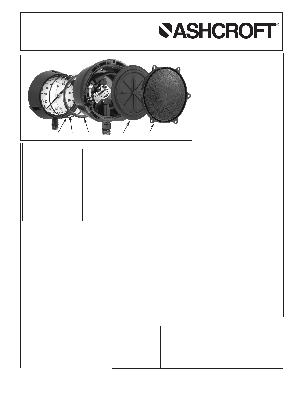
TYPICAL 45-1279_S-04L-100* GAUGE
SHOWN WITH KIT 101A202-01
LIST OF INCLUDED PARTS
41⁄
2˝ LOWER 4
1
⁄
2˝ BACK
CONN. CONN.
DESCRIPTION 101A202-01 101A203-01
ACRYLIC WINDOW 1 1
FRONT O-RING 1 1
DIAPHRAGM 1 1
REAR COVER 1 1
COVER SCREWS 4 4
THROTTLE SCREWS 2 2
GARTER SPRING – 1
FILL IDENTIFICATION 11
“O” Ring Acrylic Window Threaded Ring Elastomeric Diaphragm
with Integral “O” Ring
Rear Cover
to within 1⁄16 inch BELOW the O-ring
channel lip.
Pre-measuring fill amount is not necessary with above methods. For reference, amount of fill is approximately
400 ml. or 14 fluid oz. (4
1
⁄2˝ GA.) and
455 ml. or 16 fluid oz. (6˝ GA.).
c. Note: The liquid fill level should be
3
⁄8˝
(±
1
⁄8) as measured from the inside of the
ring at the 12:00 o’clock position.
6. On lower connection gauges, assemble
rear seal diaphragm to case.
For back connection gauges see instructions on reverse side. (Fig. 2/4).
7. Assemble rear cover and six self tapping
screws in a criss-cross pattern.
Assemble throttle screw to threaded hole in
socket.
Note: If system is monel (socket wrench
flat stamped “PHS” or “PH”) use monel
throttle screw.
8. Check appropriate box on fill identification
label, and peel off label back, and attach fill
label to gauge case.
9. If gauge is to be repackaged:
a. Include enclosed instruction sheet inside
carton.
b. Change type number on carton label to:
(1) Hermetically Sealed – 1279(*)SH.
(2) Liquid Filled – 1279(*)SL.
*Bourdon Tube System Code
Ambient 60 psi and Under
Temp. Limits Down Scale Zero
°F °C Shift Required
Weatherproof –50/150 –45/65 N/A
Hermetically Sealed –10/125 –25/50 N/A
Glycerin Filled 0/150 30/65 .15 psi
Silicone Filled –50/150 –45/65 .12 psi
Glycerin or silicone should not be used in
applications involving Oxygen, Chlorine, Nitric
Acid, Hydrogen Peroxide or other strong oxidizing agents, because of danger of spontaneous chemical reaction, ignition or explosion. Halocarbon should be specified.
Products with this fill can be ordered from
factory.
The use of fluids other than those listed in the
table above (for example, Hydrocarbon-based
oils) may result in leakage caused by a reaction between the fluid and the elastomeric
seals. Consult the factory before filling with
any other fluid.
Page 2
TYPE 1279 & 1379 SOLID FRONT
DURAGAUGE PRESSURE GAUGE
LIQUID FILL CONVERSION
INSTRUCTIONS
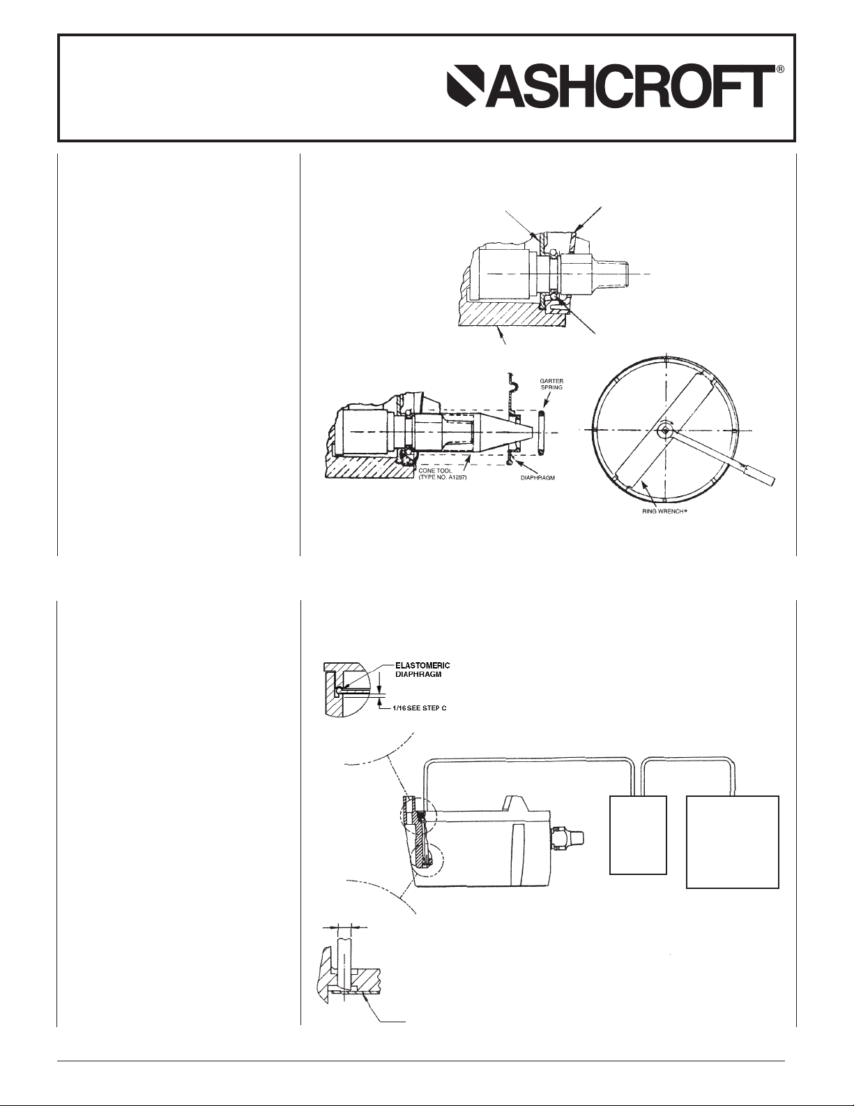
Garter Spring & Diaphragm Assembly
(Back Connection Gauge Only)
A. Place cone tool over socket shank as shown.
B. Moisten lip of socket and outer O-ring surface
with silicone oil or grease.
C. Place diaphragm with rib side facing upward over
cone into case grove.
Diaphragm O-ring must be completely in socketshank grove.
D. Place garter spring over cone as shown and slide
onto diaphragm in socket grove
E. Assemble rear cover with screws per step 7.
Front Ring Assembly (All Gauges)
A. Assemble ring to case by hand to start.
B. Place ring on wrench as shown
C. Use 1⁄2˝ drive extension and torque ring to 200 in. lb
Alternate Method
A. Tighten ring snugly by hand
B. Mark case and ring.
C. Turn ring another 100 to 120 degrees (slightly
less than 1⁄2 turn) using the ring wrench and 1⁄2˝
drive socket wrench or place the blunt end of a
wooden or plastic dowel against a ring lug and
tap with a hammer.
INSTRUCTIONS FOR USING CONE
TOOL AND RING WRENCH
Fig. 3
GARTER SPRING
DIAPHRAGM
REAR COVER
CASE
BACK CONNECTION ASSEMBLED GAUGE
Fig. 2
Fig. 3
Fig. 5
Fig. 4
A. Insert a length of
1
⁄8 ˝ diameter tubing through
the 12 o’clock position hole in the rear, solid
front portion of the case, as shown.
B. Evacuate the air from the front dial cavity while
pouring in the fill fluid through the case back.
The vacuum will displace the air with fluid.*
C. When the dial cavity is solidly filled, remove the
tubing and continue to pour the fill fluid to within 1⁄16 ˝ below the o-ring channel lip, as shown.
D. When converting a 45-1379 with the top fill hole
configuration, p/n 256A176-01 fill plug is
required and must be ordered separately.
*To prevent breakage, reduce vacuum to 15 in.
Hg for plain glass and safety glass.
VACUUM
TRAP
Ø 1⁄8 TUBING
DIAL
VACUUM
PUMP
INSTRUCTIONS FOR LIQUID FILLING
ASHCROFT
®
TYPE 1279 AND 1379
SOLID FRONT DURAGAUGE
®
PRESSURE GAUGES USING A
VACUUM PUMP
© 2007 Ashcroft Inc., 250 East Main Street, Stratford, CT 06614 USA, Tel: 203-378-8281, Fax 203-385-0402 www.ashcroft.com
All sales subject to standard terms and conditions of sale. All rights reserved. I&M008-10090 (84B276) Rev 5/05 P5/07
 Loading...