

Page 1
Installation and Maintenance Instructions for
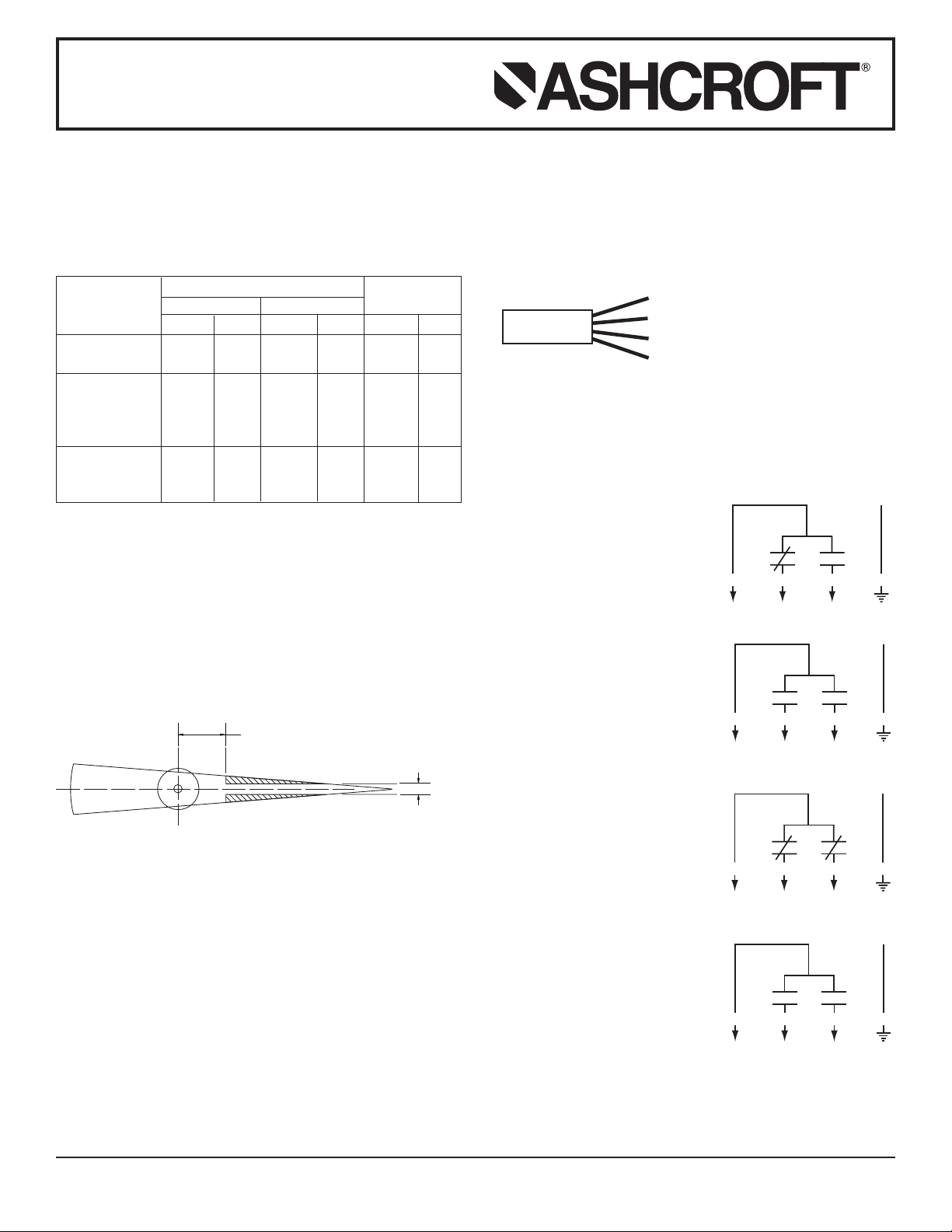
˝
BLACK
BLUE
BROWN
GREEN/YELLOW
CABLE
HIGH AND LOW (XED)
LOW HIGH
DOUBLE HIGH (XEE)
LOWEST HIGHEST
DOUBLE LOW (XEF)
LOWEST HIGHEST
OFF HIGH AND LOW (XEG)
LOW HIGH
ASHCROFT®Type 2265 Electrical Contacts
ELECTRICAL CONTACT
SWITCHING CAPACITY:
250V maximum voltage
30W DC maximum switching power
50VA AC maximum switching power
1A maximum current
Accuracy with no magnet effect, see paragraph #3
DURAGAUGE® PRESSURE GAUGE DURATEMP
FUNCTION
Pointer Carrying
Actuating Arm 0.5% 1% 1% 1.5% 1.5% 2%
Pointer Carrying
one Contact 20%
Beyond Contact
Point 1% - -1.5% - 2% -
Contact Differential
Between Make and
Break - -1% - -1.5% - 2%
NOTE: These tolerances are to be added to the standard tolerance of the gauge or thermometer.
Above 30 psi 30 psi and below
Indication Contact Indication Contact Indication Contact
THERMOMETER
INSTALLATION
1. Remove instrument ring and replace window with electric
contacts. Make sure gasket is reinstalled as it was used with
the window. Gasket is not reused with 6˝ DURATEMP
®
Thermometer type 600-04 and 600-03.
2. The forked actuating arm is designed to fit freely over the
standard DURAGAUGE
cial pointers and all DURATEMP
®
Pressure Gauge pointer, but spe-
®
Thermometer pointers
need to be modified as shown in order to fit in the fork.
0.500˝
0.150
WIRING
Wire contact according to its corresponding schematic as
shown. Contact conditions are shown at lowest pointer position. Connect the wires to the corresponding colored wire from
the cable provided with the contact, and then plug the cable
into the contact. For single low or high contact operation, follow
the (XED) schematic and tape off the unused wire.
®
ADJUSTMENT
Take the adjusting key provided and place over the square
shaft in the center of the hood, push down, rotate the adjusting
arm and then move the red set arms to the desired location on
the dial.
DEFINITIONS
XED High and Low Arrangement –
the low contact is closed and
the high contact is open
when the pointer is at its lowest dial reading.
XEE Double High Arrangement –
both contacts are open
when the pointer is at its
lowest dial reading. Due to
the high hairspring torque of
these contacts, the gauge
pointer may be slightly above
its lowest dial reading.
XEF Double Low Arrangement –
both contacts are closed
when the pointer is at its low-
3. Disconnect power before readjusting magnets. The contacts
est dial reading.
are equipped with adjustable magnets to eliminate contact
chatter caused by vibration. The magnets as received are
set to have no effect on the contacts. For applications involving vibration, the magnet screw should be turned in until the
magnet’s effect eliminates the vibration. Secure the magnets
with Loctite or other suitable material. The force of the magnets could add up to 3% to 6% accuracy error to the values
in the table.
4. Place the contact unit on the gauge so that the forked actu-
XEG “Off” at High and Low and
“On” In-between
Arrangement – the contacts
are closed in the center portion of the dial and open at
the extremes of the range.
ating arm fits over the indicating end of pointer. If the fork
hits the dial, clip the tip off or bend the fork out so that it no
longer interferes with any portion of the dial. Gauge pointer
may be bent up to fit into the forked actuating arm.
5. Replace window retaining ring.
© Ashcroft Inc., 250 East Main Street, Stratford, CT 06614-5145, Tel: 203-378-8281, Fax: 203-385-0499, email: info@ashcroft.com, www.ashcroft.com
All sales subject to standard terms and conditions of sale. I&M008-10165 (250-2950) 02/09
 Loading...