

Page 1
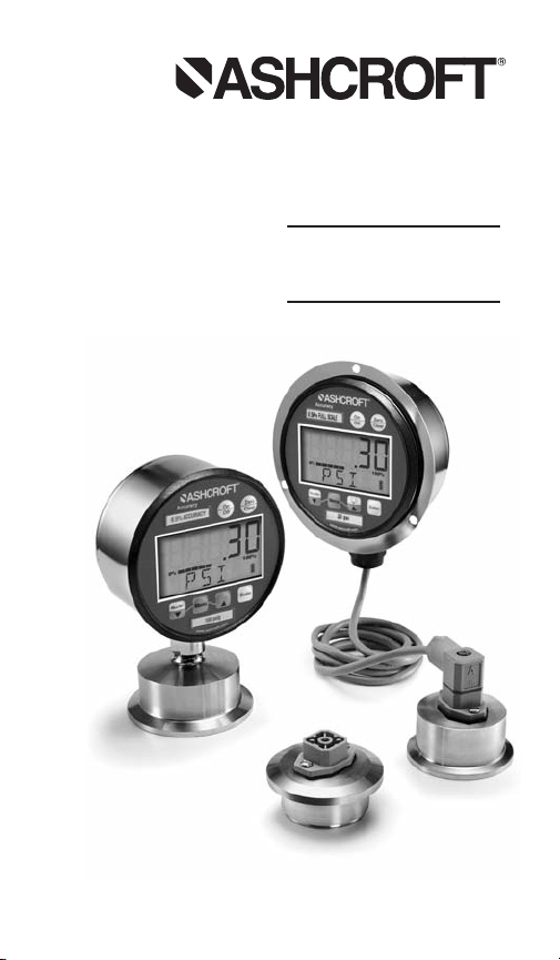
Digital
Sanitary
Gauge
Operating
Instructions
I&M008-10162-10/08 Rev. 09/11
Page 2

Congratulations on your purchase of the Ashcroft
®
digital sanitary gauge. This feature-packed gauge
offers a menu-driven display for easy customization.
User selectable features include 12 units of measure-
ment, password protected calibration and disable
functions, adjustable bar graph and update rate. A
five digit display for maximum resolution is standard.
Optional 4-20mA output, switching and line- power
add to the versatility of the gauge. With the range
printed on the keypad, Ashcroft digital gauges meet
ASME B40.7 specification. See a complete listing of
product features and specifications on pages 16.
– 2–
Page 3

TABLE OF CONTENTS
Quick Reference ............................................4-5
Keypad Functions ..........................................6-8
• ON/OFF KEY
• ZERO/CLEAR KEY
• MIN/MAX KEY
(down arrow key)
• MENU KEY
• BACKLITE KEY
(up arrow key)
• ENTER KEY
MENU Functions (MENU Mode) ................................8-15
• Engineering Units
• CONFIG Mode
• Set Password
• Recalibration of Gauge
• Zero Key Adjustment
• Disabling Menu Options
• Bar Graph Options
• Auto Off Options
• Update Options for Displayed Pressure
• Dampening Options
• Backlite Options (Backlite Optional)
• Set Switch(es) Option(s) (Switches Optional)
Specifications ................................................16
Ranges ........................................................17
Display Messages ..........................................17
Wiring Diagrams ........................................18-29
Gauge Installation & Maintenance ....................30-32
• Mounting
• Battery Replacement & Installation
– 3–
Page 4
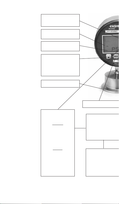
.88˝ high digital display (41⁄2˝ case)
.60 high digital display(3˝ case)
Bar graph
% of full scale
Flashing display when unit
pressured below zero
Press to indicate minimum
or maximum pressure
gauge has measured
Press again to return to
pressure units
316LSS
UNITS (Pressure)
ENGLISH
INHG
PSI*
INH2O
@ 4°C, 20°C, 60°F
FTW
FTSW
METRIC
BAR
MBAR
KPA
CMH2O
KG/CM2
QUICK RE
Press to read menu
UPDATE RATE
(Pressure measurement
per second)
10x (100 MS)*
5x (200 MS)
2x (500 MS)
1x (1 Sec)
BACKLITE
(Off options)
Never
2 SEC
5 SEC*
15 MIN
30 MIN
– 4–
Page 5
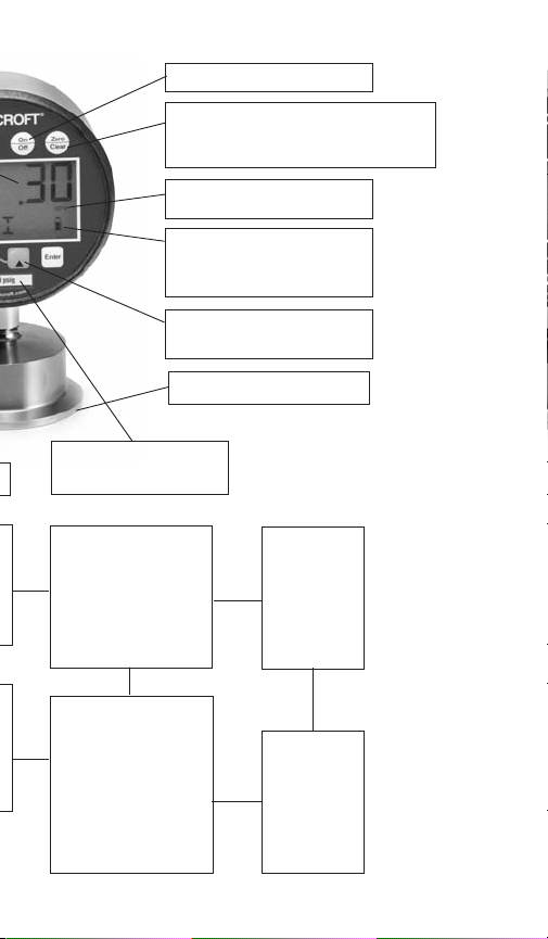
Press to turn unit on or off
While in unit of measurement mode (eg: psi),
press the ZERO CLEAR button to rezero the
gauge. This feature functions when displayed
pressure is within ±5% or 10% of zero value
pressurized beyond full-scale
This bar graph indicates battery level;
the more segments, the closer the
battery is to full charge (only dis-
played on units with battery
Press to turn backlite on or off
Range on keypad;
complies with ASME B40.7
AUTO OFF
(Turns unit off after
option selected)
Never*
2 minutes
5 minutes
15 minutes
30 minutes
Flashing display when unit
(backlite optional)
12-20RA Surface finish
CALIBRATE
Zero and span
adjustments,
password
protected
DAMPENING
(Takes pressure reading
and averages
process pressure
None*
Avg 2
Avg 4
Avg 6
Avg 8
– 5–
DISABLE
Allows for
“lockout” of
MENU
options
*Indicates Default
Page 6
KEYPAD FUNCTIONS
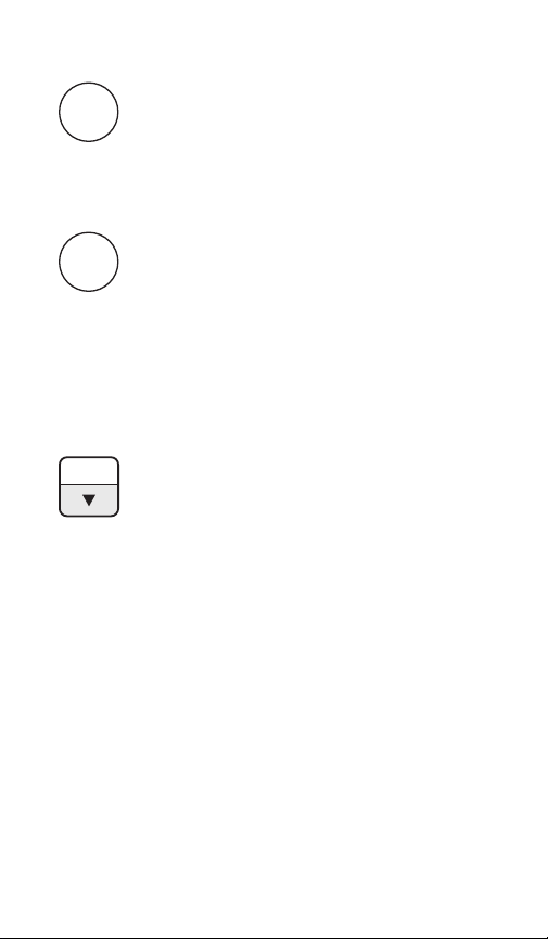
Turns the gauge on and off. When pressing the
ON/OFF
ON/OFF key while in the off position, gauge startup display first indicates the software version
followed by the model number and gauge pressure range. The gauge will then display indicated
pressure and be ready for use.
Press this key for one second prior to gauge
ZERO
usage to rezero any initial zero shift. If zero shift
CLR
is greater than programmed zero allowance, the
gauge will display OFSET (blinking) for 1 second, then return to the measure mode. To clear
minimum and maximum values, press
ZERO/CLR button (when min/max values are
indicated). Gauge will auto advance once zeroed.
MAX/MIN
The Max/Min key allows review of minimum and
maximum pressure values since unit start-up or
last push of the clear key. Press key to:
1) Indicate maximum pressure.
2) Indicate minimum pressure.
3) Exit MAX/MIN mode and return the unit to
pressure measurement mode. To clear minimum and maximum values press ZERO/CLR
key (must be in MAX/MIN mode).
(down arrow key) is used in the MENU
The
mode, see following MENU key section.
– 6–
Page 7
MENU
Key for gauge
with Backlite
Key for gauge
without Backlite
displayed with
(up arrow
icon only)
KEYPAD FUNCTIONS
This key allows for customization of the gauge.
Pressing the MENU key allows cycling through
the main MENU items; UNITS, CONFIG, GRAPH,
OFF, UPDAT & DAMP. Any item changed in the
Menu become the new default setting(s).
Revised settings are saved in the event of power
loss.
The
(up arrow key) or (down arrow key)
on the keypad allows for scrolling through the
MENU options to increase or decrease numeric
values as required. If in the menu mode, gauge
will automatically advance to measure mode
once selected MENU item has been set.
This key manually turns the backlite on or off.
five options are available. They include NEVER,
10 sec, 30, sec, 1 min, 5 min*. With the NEVER
option, the gauge BACKLITE will remain lit
whenever the gauge is in the ON mode or until
the BACKLITE button is pushed again. Options,
10 sec, 30 sec, 1 min, 5 min*. allow the BACKLITE to automatically turn-off after a selected
period of time.
To use the BACKLITE option:
Step 1: Press the MENU key.
Step 2: Press the
(up arrow key) or (down
arrow key) until the word LITE appears.
Step 3: Press ENTER.
Step 4: Press the
(up arrow key) or (down
arrow key) to select the BACKLITE option.
Step 5: Press the ENTER key to finalize your
choice of LITE options.
– 7–
Page 8

KEYPAD FUNCTIONS
This key allows for selecting gauge features in the
ENTER
menu finalizing selection. Use of the enter key is
described throughout operating instructions.
MENU OPTIONS
UNITS: 12 units of measurement are available: psi, mmHG,
inH
O with three temperature options: 20°C, 60°F, 4°C*,
2
mBar, inHg, ftH
O, mPa, kPa, kg/cm2and bar.
2
Step 1: Press the MENU key until the word UNITS appears.
Step 2: Press Enter.
Step 3: Press the
(up arrow key) or (down arrow
key) to select the required unit of measure.
Step 4: Press ENTER to finalize the UNIT selection.
Note: For inH
press the
0 range with three temperature options,
2
(up arrow key) and (down arrow key) to
select the desired temperature, then press ENTER to finalize the UNIT selection.
CONFIG: This option allows access to additional Menu
options. Options include:
• ENTPW or enter password (this appears as a sub-menu
in the CONFIG mode if a user password has been set).
• RECAL (allows for zero, span and mid-scale calibra-
tion of the gauge).
• 0bUTN or zero key (allows for adjustment of % of
range that can be zeroed),
• dISAb, allows for disabling MENU options.
• SETPW: This feature allows for a user defined numer-
ic password. If a user password is not set, all features
in the CONFIG mode will be accessible without a
password. If a user password is set, all items in the
CONFIG menu options are accessible with or without
a user password. If a user password is programmed,
it will be required to access the CONFIG menu options.
*Indicates default.
– 8–
Page 9

KEYPAD FUNCTIONS
MENU FUNCTIONS
How to Use Your Menu Functions
To set a user password (SETPW):
Step 1: Press the Menu key on the keypad
Step 2: Press the
(up arrow key) or (down arrow
key) until the word CONFIG appears.
Step 3: Press Enter. The word SETPW appears on the
gauge display
Step 4: Press Enter. A five digit numeric password is now
required.
Step 5: Press the
(up arrow key) or (down arrow
key) on the keypad to select the first digit of the password.
Step 6: Press ENTER.
Step 7: Repeat until the five-digit password is shown on
the gauge display.
Step 8: Press ENTER.
Note: to erase password at any time while in the SETPW
(set password) mode, press the ZERO/CLEAR key. The
user will be prompted to reprogram the password once the
five-digit password is entered. The gauge will display SAVE.
Step 9: Press Enter to save the password setting.
ENTPW: Once a user password has been established and
entry into the CONFIG mode is required, the user will be
prompted to ENTPW or enter password.
Follow setup steps 4-8 above.
RECAL: or recalibrate allows for zero, mid-scale, full-scale
and factory default calibration of the gauge. The RECAL
feature also allows for recalibration of gauges with
4-20mA output.
*Indicates default.
– 9–
Page 10

MENU FUNCTIONS
To use RECAL option:
Step 1: Press the Menu key on the keypad
Step 2: Press the
(up arrow key) or (down arrow
key) on the keypad until the word CONFIG appears.
Step 3: Press Enter.
Step 4: Enter user password if it has been programmed.
Step 5: Press
(up arrow key) or (down arrow key)
until the word RECAL appears.
Step 6: Press Enter.
Step 7: The gauge will now flash between INPUT and unit
of measure on the lower line and .00 on the top line. Apply
zero pressure to the gauge.
Step 8: Press Enter. Zero pressure is now set.
Step 9: The gauge will display full-scale pressure. Apply
full-scale pressure to the gauge.
Step 10: Press Enter. Full-scale pressure is now set.
Step 11: The gauge will now display mid-scale pressure.
Apply mid-scale pressure to the gauge.
Step 12: Press Enter. Mid-scale pressure is now set.
(Note: For compound ranges this recalibration is zero,
full-scale, mid-scale and full-vac.)
FOR FACTORY CALIBRATED SETINGS:
Step 13: To reinstate factory calibrated settings for zero,
full-scale and mid-scale press the
(down arrow key)
Menu key until the word FACT appears.
Step 14: Press Enter. Factory calibration settings are now
reinstated.
Step 15: After zero, full-scale and/or mid-scale or factory
default calibration have been set, the word SAVE appears
on the gauge display.
Step 16: Press Enter to finalize calibration.
*Indicates default.
– 10 –
Page 11

MENU FUNCTIONS
Note: Calibration of Zero, mid-scale or span can be set independently of each other. For instance, if only full-scale calibration is required, press the
(down arrow key) until the
gauge display indicates full-scale pressure. Press Enter and
proceed as indicated above. Calibration of zero, midscale and
full-scale is recommended when recalibrating the gauge.
ZERO KEY (0bUTN): This feature allows the user to select
percent of full-scale at which the gauge can be rezeroed
using the Zero/Clear key on the keypad. Options include 5%
full-scale*, 10% full-scale or DISAB (disable of the zero key).
To use ZERO option:
Step 1: Press the Menu key on the keypad.
Step 2: Press the
(up arrow key) or (down arrow
key) until the word CONFIG appears.
Step 3: Press Enter.
Step 4: Enter user password, if it has been programmed.
Step 5: Press the
(up arrow key) or (down arrow
key) until the word 0bUTN (zero key) appears.
Step 6: Press Enter.
Step 7: Press the
(up arrow key) or (down arrow
key) to select 5PCT (5% full-scale), dISAb (disable zero
key) or 10PCT (10% full-scale).
Step 8: Press Enter to finalize the selection.
DISAB: or disable: This feature allows the user to dISAb
(or disable) or ENAb (enable) items in the MENU. Some
keypad keys can also be enabled or disabled. Any or all
MENU items can be enabled or disabled.
To use DISAB option:
Step 1: Press the Menu key on the keypad.
Step 2: Press the
(up arrow key) or (down arrow
key) until the word dISAb appears.
*Indicates default.
– 11 –
Page 12

MENU FUNCTIONS
Step 3: press ENTER. The current setting (ENAB or dISAB)
will be displayed.
Step 4: Press the
(up arrow key) or (down arrow
key) on the keypad to select a setting.
Step 5: Press ENTER To finalize the setting.
GRAPH: This option allows the user to change the BAR
graph on the gauge display to correspond to any desired
pressure within the pressure limits of the gauge. This
option is useful when identifying a select portion of the
full-scale range of the gauge. The default setting for the
GRAPH is zero and full-scale pressure. For compound
gauges, the default setting for zero is set at full-scale vacuum. Full-scale pressure is set at the positive pressure as
displayed on the gauge keypad.
For gauges supplied with the 4-20mA output option, the
default is 4mA equals 0% of the bar graph and 20 mA
equals 100% of the bar graph.
Changing the bar graph to a pressure other than 0 and
100% of range will also change the 4-20mA output to correspond with the new bar graph pressures for 0 and 100%.
To use GRAPH option:
Step 1: Press the MENU key.
Step 2: Press the
(up arrow key) or (down arrow key)
on the keypad until the word until the word GRAPH appears.
Step 3: Press ENTER . The gauge display will indicate the
set full scale pressure range setting on the top line. The
middle line indicates the bar graph at 100% of full-scale.
The bottom line of the display will indicate SETFS to set
the full-scale range as displayed by the bar graph and 420mA.
Step 4: Press the
(up arrow key) or (down arrow key)
on the keypad to increase or decrease gauge value at
100% of range.
*Indicates default.
– 12 –
Page 13

MENU FUNCTIONS
Step 5: Press the ENTER key to finalize your choice. The
gauge display will now display SET. After two seconds the
screen will display the pressure value for 0% on the top
line. The middle line indicates the bar graph at 100% of
fullscale. The bottom line will display SET 0.
Step 6: Press the
(up arrow key) or (down arrow
key) on the keypad to increase or decrease gauge value at
0% of range.
Step 7: Press the ENTER key to finalize your choice. The
new values for the bar graph and 4/20mA settings have
now been saved.
OFF: This option sets the amount of time before the gauge will
turn itself off. Offerings are Never*, 30MIN,10MIN, 5MIN, 2
MIN.
To use the OFF option:
Step 1: Press the MENU key.
Step 2: Press the
(up arrow key) or (down arrow
key) until the word OFF appears.
Step 3: Press ENTER.
Step 4: Press the
(up arrow key) or (down arrow
key) to select the desired OFF time.
Step 5: Press the Enter key to finalize the OFF setting.
UPDATE: This option allows for changing the rate at which
pressure is updated on the display screen. This feature is
useful with rapid changes in process pressure that may
cause flutter of the display. Options are 100ms*, 1 sec,
500ms and 200ms, updates per second or 100ms*.
Since customer processes vary, update rates should be
selected based on the application.
To use the UPDATE option:
Step 1: Press the MENU key.
*Indicates default.
– 13 –
Page 14

MENU FUNCTIONS
Step 2: Press the (up arrow key) or (down arrow
key) until the word UPDATE appears.
Step 3: Press Enter.
Step 4: Press the
(up arrow key) or (down arrow
key) to select an update rate.
Step 5: Press ENTER to finalize the selection.
DAMP or dampening: with five different options, this mode
allows for taking process pressure readings and averaging
them. This option is particularly useful to stabilize minor
process fluctuations. The options are NONE*, AVG 8, AVG
6, AVG 4, AVG 2.
Step 1: Press the MENU key until the word dAMP appears.
Step 2: Press Enter
Step 3: Press the
(up arrow key) or (down arrow
key) to select a dampening option.
Step 4: Press the ENTER key to finalize your Damp option.
(This Menu item is only seen on units with the switch option)
SWSET: Allows for setting switch setpoints. The gauge is
offered with one or two SPDT switches. If (one) SPDT
switch is ordered the menu option is SW1. If (two) SPDT
switches are ordered, the MENU options are SW1 and SW2.
Step 1: Press the MENU key.
Step 2: Press the
(up arrow key) or (down arrow
key) on the keypad to select the switch to be set. (If two
switches are present.)
Step 3: Press ENTER. The top line of the gauge display will
indicate pressure at 60% of the fullscale gauge range* or
the most recent switch setpoint. The middle line of the display will indicate a bar graph that displays the pressure
position within the pressure range. The bottom line will
display SETPT (blinking).
*Indicates default.
– 14 –
Page 15

MENU FUNCTIONS
Note: Setpoints are limited to the full-scale pressure range
of the gauge.
Step 4: Press the
(up arrow key) or (down arrow key)
on the keypad to increase or decrease switch set-point
Step 5: Press the ENTER key to finalize switch setpoint. The
gauge will display SET. After two seconds, the top line will
indicate RETRP pressure. The bottom line will read SET.
Step 6: Repeat above to set RETRP (retrip value) If the
gauge is supplied with (one) setpoint, the screen will
advance to the measurement mode. If (two) switches are
supplied the display will advance to SW2.
Repeat the aforementioned if the gauge is supplied with
two switches.
Notes: The bar graph will increase or decrease as any
setpoint pressure is adjusted. The bar graph indicates
switch setpoint position within the full-scale pressure
range of the gauge.
The switch setpoint unit of pressure measurement corresponds with the current set unit of measure of the gauge.
If gauge unit of measurement is changed after switch(es)
is set, switch setpoint(s) will automatically be updated to
correspond with revised unit of measurement. Switch
deadband is the difference between the SETPT (setpoint)
and the RETRP (retrip) pressure.
– 15 –
Page 16

DIGITAL SANITARY GAUGE SPECIFICATIONS
Type Conventional Tri-clamp: 2032 (battery), 2132
Accuracy: Terminal Point
Full Scale .25% F.S. Accuracy:
Case Size 3˝
Case Material/Finish (3˝) 300 series SS, Electropolished
Case Enclosure Rating Weatherproof, IP65, NEMA 4
Wetted Parts 316 SS
Tri-Clamp Connection Direct, in-line 11⁄2 ˝,2 ˝, Ashcroft remote in-line (XRE),
Seal Surface Finish 12-20Ra
Connection Location Lower
Ranges 15 psi thru 1,000 psi including metric, compound & vac
Process Temp. Limits
Ambient Temp.Limits
Temperature Error ± .22% per 10°F, (12°F) (Span and Zero shift can be eliminated
Storage Temperature -4°F / 158°F (-20°C / 70°C)
Overrange Pressure 2x range of gauge
DISPLAY
Type LCD
Display Digits 5 Digits
Character Height .60˝
Backlite Off By Default
Bar Graph Yes
Battery Life 1000 Hrs., Battery Life Indicator - standard
Agency Approvals CE (excludes XRE variation)
KEYPAD FUNCTIONS
On/Off Manually Turns Unit On & Off (auto off options in menu)
Zero/Clear Zeros Display or Clears Min/Max Values When Displayed
Min/Max Arrow Key Stores Min & Max Values, Arrow Key allows for scrolling
Menu Allows for changes to default settings (See Below)
Backlite (optional) Arrow Key Manually Turns Backlite On & Off (auto off options in menu),
Enter Selects Items In the Menu
MENU MODE
Engineering Units (Units) 10units of measurement are available psi, inh
Configuration Mode(Config) Allows for changes to default settings of gauge
Bar Graph (Graph) Allows for adjustment of bargraph & 4-20(optional feature)
Auto Off (Off) Allows for changes to auto off of gauge 5 Options:, 30 Min.,
Update Rate (Update) 4 Options: 100mili-sec, 1sec, 500mili-sec,200mili-sec,
Dampening (Damp) 6 Options: None, Average 8, 6, 4, 2 times per 100ms
Backlite Lit (optional) 5 options: NEVER, 10 sec, 30, sec, 1 min, 5 min.
Zero Disable Zero “lockout” feature
Field Recalibration Zero, Span & Midscale (password protected)
Calibration Allows for recalibration of zero & span
OPTIONS
4-20mA Display
Line Powered 12-36 Vdc
Switching (XU1 code) (1) or (XU@ code) (2) SPDT switches, (requires line
Remote Mount Seal (RE code) standard with 10 shielded cable
Notes (1)3 shielded cable standard
(2) Rezero gauge often after exposure to elevated temperatures and use.
(3) The 2030 Series Digital Gauge is not suitable for an autoclave.
In-line Tri-clamp: 2036 (battery), 2136 (4-20mA), 2232 (line)
(2)
14°F / 275°F (-10°C / 135°C) to withstand clean in place
(3)
(CIP) & steam in place (SIP)
14°F / 140°F (-10°C / 60°C)
by rezeroing the gauge at operating temperatures. Temperatures
must be within process temperature limits)
Material Traceability Certification to EN 10204: 2004 3.1 standard
thru Menu items
Arrow Key allows for scrolling thru Menu items
Allows Scrolling Through Menu To Select Available Options
options: 20°C, 60°F, 4°C*, mmHg, fth
10 Min., 5 Min., 2 Min., Never
(includes factory default calibration)
power), (max. contact 30Vdc,1 amp, 125Vac, .5 Amp)
Switches adjustable to 100% of range
(1)
(4-20mA), 2232
o with 3 temp.
2
o, mPa, kPa, kg/cm2& bar
2
– 16 –
(1)
(line)
Page 17
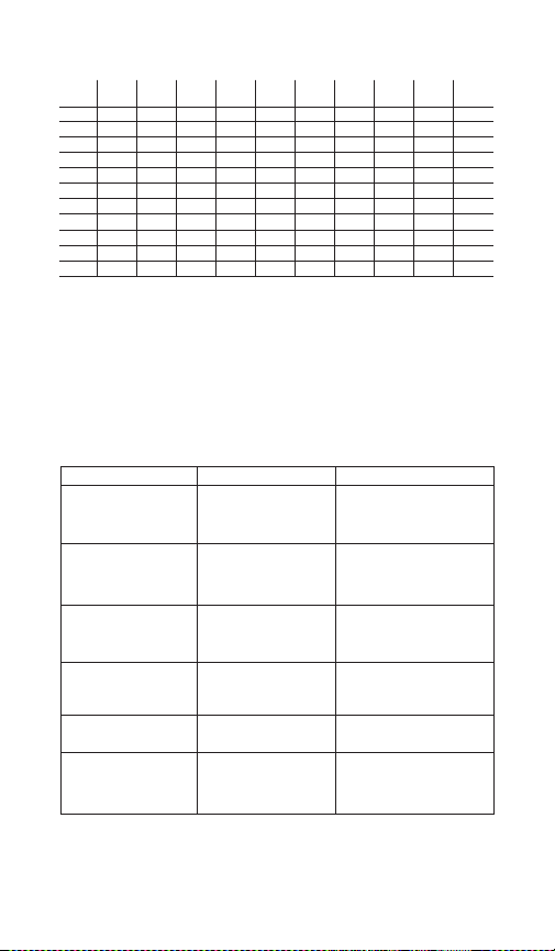
DIGITAL SANITARY GAUGE RANGES:
Comp. mmHg in.Hg In. mm ft. Bar/
psi (psi) (press.) (press.) H2OH2O mBar H2O mPa kPa ksc
-15/0/15
1500 60 800 60 250 30 200 2
-15/0/30
2000 100 1000 100 300 60 300 4
-15/0/60
30
60 300 300 600 300 800
100 400 400 1000 400 1000
160 600 600 1500 600 1600
200 800 800 2000 1000 2500
300 1000 1000 2500 4000
600 4000
800 5000
3000 160 160 400 160 400 6
-15/0/100
200 200 500 200 600 10
DISPLAY MESSAGES:
Display/Problem Description Action
No Battery Icon
Display (applicable to
gauges with batteries
OFSET (blinking)
Menu button disabled
Unit of measure
selected in Menu
displays N/A
I can’t set the
password I want
I can’t access items in
the main Menu
Gauge has <10%
battery life left
Zero/Clear button
pushed when pressure
displayed is beyond set
rezero pressure limit
Gauge is in
Max/Min mode
Resolution at full scale
pressure range
exceeds 50,000 counts
00000 is not a valid
password
Items that cannot be
accessed have been
disabled
Replace batteries
Only rezero the gauge within
limits of setting in Menu
Push Max/Min button until
unit of measure is displayed
on keypad
Choose another unit of
measure
Select a different password
Enable item(s) in the Menu.
See Menu/CONFIG and
diSAb or DISABLE
– 17 –
Page 18
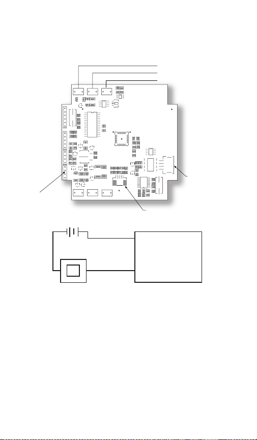
WIRING DIAGRAM
LOOP+
LOOP–
T7
D9
D7
Y1
D10
C14
T9
U5
V1
F1D1
C3
C7
R7
R2
J1
1
1
J6
C2
R22
R20 C17
D11
U7
D14
D1
C15
R18
D5
R23
R24
D13
R14R16
J3
J7
1
Q4
D16
D6
D15
D3
D12
T10
T12
T11
+24V
GND
EGND
FID3
321CO21–
D8
Q2
J5
J3
C4
R9
R10
R11
R12
R13
Q1
C10
C9
R6
C5
L1
U4
FO7
R8
FID4
V2
R1
R5
C1
R4
C6
C8
DQ/TB 2003
Y2
J2
FID2
V6
R21
Q3
T8
ECND
FID6
FID5
R19
Red (+ exec.) A
Black (– exec.) B
Battery Input
Keypad Input
Sensor Input
Shield
+
+
–
POWER
SUPPL Y
(+)
(–)
METER
PLC
SCADA
GAUGE
–
V+
V–
Red
Black
(A)
(B) (–)
Loop Powered 4-20mA (Type 2132)
2 conductor, 20 AWG shielded
– 18 –
Installation Procedure for 2132:
ESD precautions should be taken. See page 31 for details.
1. Ensure all power is off/disconnected from the circuit.
2. Connect the red wire (A) to the positive power terminal.
3. Connect the black wire (B) to the positive terminal on the
meter.
4. Connect the negative side of the meter to the negative
power terminal.
Note: Meter should be installed on the black wire only.
Page 19
WIRING DIAGRAM
1000
750
500
250
0
620100
30
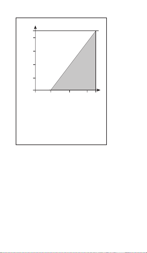
Load Limitations 4-20mA Output Only
RL-Loop Resistance in Ohms
Loop Supply Voltage (Vdc)
OPERATING
REGION
Vdc MIN = 12V + [0.022A X (RL) ]
= RS+ R
R
L
W
RL= Loop Resistance (ohms)
= Sense Resistance (ohms)
R
S
= Wiring Resistance (ohms)
R
w
– 19 –
Page 20
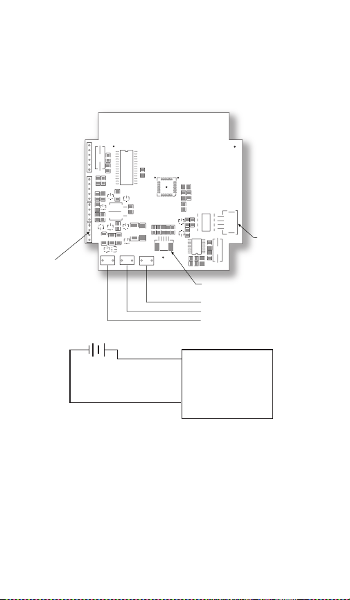
WIRING DIAGRAM
Y1
V1
F1D1
C3
C7
R7
R2
J1
1
1
J6
C2
R22
R20 C17
D11
U7
D14
D1
C15
R18
D5
R23
R24
D13
R14R16
J3
J7
1
Q4
D16
D6
D15
D3
D12
T10
T12
T11
+24V
GND
EGND
FID3
321CO21–
D8
Q2
J5
J3
C4
R9
R10
R11
R12
R13
Q1
C10
C9
R6
C5
L1
U4
FO7
R8
FID4
V2
R1
R5
C1
R4
C6
C8
DQ/TB 2003
Y2
J2
FID2
FID6
FID5
Shield
Black (–exec.) D
Red (+exec.) C
Battery Input
Keypad Input
Sensor Input
+
POWER
SUPPL Y
(+)
( – )
GAUGE
–
V+
V–
Red (C)
Black (D)
Line Powered (Type 2232)
2 conductor, 20 AWG shielded
Installation Procedure for 2274:
ESD precautions should be taken. See page 31 for details.
1. Ensure all power is off/disconnected from the circuit.
2. Connect the red wire (C) to the positive power terminal.
3. Connect the black wire (D) to the negative power terminal.
– 20 –
Page 21
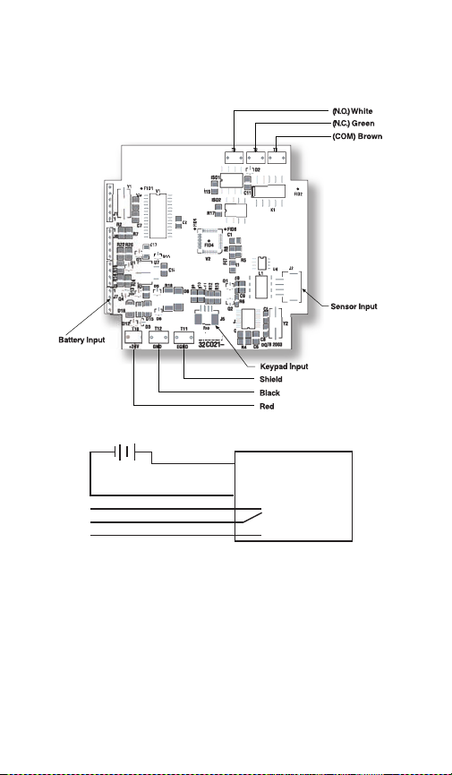
WIRING DIAGRAM
(–exec.) F
(+exec.) E
+
POWER
SUPPL Y
(+)
(–)
GAUGE
–
V+
V–
Red (E)
Black (F)
White (NO)
Green (NC)
Brown (Common)
•
Line Powered with (1) SPDT switch (Type 2232 XU1)
5 conductor, 22 AWG shielded
Installation Procedure for 2232 XU1:
ESD precautions should be taken. See page 31 for details.
1. Ensure all power is off/disconnected from the circuit.
2. Connect the red wire (E) to the positive power terminal.
3. Connect the black wire (F) to the negative power terminal.
Wiring the Switch:
Normally Open: Use the white and brown wires.
Normally Closed: Use the green and brown wires.
– 21 –
Page 22
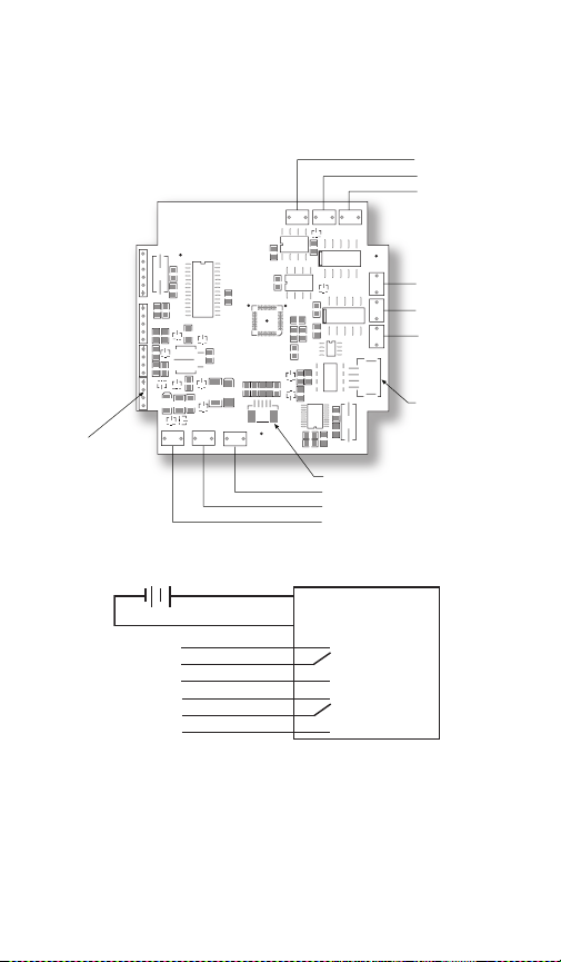
WIRING DIAGRAM
Y1
V1
F1D1
C3
C7
R7
R2
J1
1
1
J6
C2
R22
R20 C17
D11
U7
D14
D1
C15
R1 8
D5
R23
R24
D13
R14 R16
J3
J7
1
Q4
D16
D6
D15
D3
D12
T10
T12
T11
+24V
GND
EGND
FID3
321CO21–
D8
Q2
J5
J3
C4
R9
R10
R11
R12
R13
Q1
C10
C9
R6
C5
L1
U4
FO7
R8
FID4
V2
R1
R5
C12
C13
C1
R4
C6
C8
DQ/TB 2003
Y2
J2
T4
T6
T5
FID2
C11
K1
K2
K2
D2
T3
T2
T1
ISO 1
R15
ISO 2
FID6
FID5
R17
(N.O .) White
(COM) Brown
(N. C. ) Green
(N.O.) Yellow
(N.C.)
Blue
(COM) Orang e
Shiel d
Blac k (–exec.) G
Red (+exec.) H
Battery Input
Ke ypad Input
Sensor Input
SWITCH 1
SWITCH 2
+
POWER
SUPPLY
(–)
GAUGE
–
V+
V–
(+)
Red (G)
Black (H)
Switch 1
Switch 2
Blue (NO)
Orange (NC)
Brown (Common)
•
Violet (NO)
Yellow (NC)
Grey (Common)
•
Line Powered with (2) SPDT switches (Type 2232 XU2)
8 conductor, 22 AWG shielded
– 22 –
Page 23

Installation Procedure for 2232 XU2:
ESD precautions should be taken. See page 31 for details.
1. Ensure all power is off/disconnected from the circuit.
2. Connect the red wire (G) to the positive power terminal.
3. Connect the black wire (H) to the positive meter terminal.
Wiring Switch 1:
Normally Open: Use the white and brown wires.
Normally Closed: Use the green and brown wires.
Wiring Switch 2:
Normally Open: Use the yellow and orange wires.
Normally Closed: Use the blue and orange wires.
– 23 –
Page 24
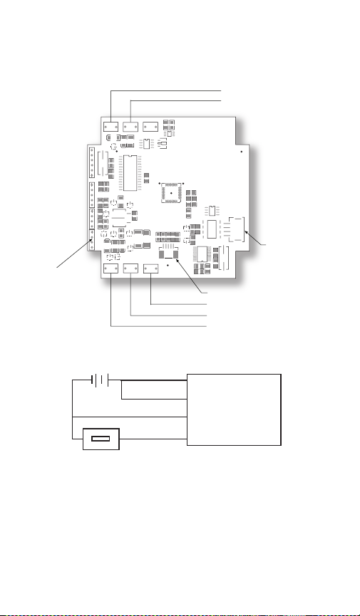
WIRING DIAGRAM
LOOP+
LOOP–
T7
D9
D7
Y1
D10
C14
T9
U5
V1
F1D1
C3
C7
R7
R2
J1
1
1
J6
C2
R22
R20 C17
D11
U7
D14
D1
C15
R18
D5
R23
R24
D13
R14R16
J3
J7
1
Q4
D16
D6
D15
D3
D12
T10
T12
T11
+24V
GND
EGND
FID3
321CO21–
D8
Q2
J5
J3
C4
R9
R10
R11
R12
R13
Q1
C10
C9
R6
C5
L1
U4
FO7
R8
FID4
V2
R1
R5
C1
R4
C6
C8
DQ/TB 2003
Y2
J2
FID2
V6
R21
Q3
T8
ECND
FID6
FID5
R19
Red (I)
Black (J)
Shield
Green (L)
White (K)
Battery Input
Keypad Input
Sensor Input
+
+
–
POWER
SUPPLY
(+)
(–)
(–)
METER
GAUGE
–
V+
V–
White (K)
(+)
Red (I)
Green (L)
Black (J)
PLC
SCADA
Line Powered/Loop Powered 4-20mA (Type 2232 XAO)
4 conductor, 20 AWG shielded
– 24 –
Page 25

Installation Procedure for 2232 XAO:
ESD precautions should be taken. See page 31 for details.
1. Ensure all power is off/disconnected from the circuit.
2. Connect the white wire (K) to the positive power terminal.
3. Connect the green wire (L) to the negative power terminal.
4. Connect the red wire (I) to the positive power terminal.
5. Connect the black wire (J) to the positive meter terminal.
6. Connect the negative power terminal with the negative
meter terminal.
Note: Meter should be installed on the black wire only.
If red/black wires are connected prior to the green/white
and power is connected, output may be damaged due to
overloading.
Warning: Using multiple power sources for line and loop
power is not recommended as it may cause damage to
the unit.
– 25 –
Page 26
LOOP+
LOOP–
T7
D9
D7
Y1
D10
C14
T9
U5
V1
F1D1
C3
C7
R7
R2
J1
1
1
J6
C2
R22
R20 C17
D11
U7
D14
D1
C15
R18
D5
R23
R24
D13
R14R16
J3
J7
1
Q4
D16
D6
D15
D3
D12
T10
T12
T11
+24V
GND
EGND
FID3
321CO21–
D8
Q2
J5
J3
C4
R9
R10
R11
R12
R13
Q1
C10
C9
R6
C5
L1
U4
FO7
R8
FID4
V2
R1
R5
C1
R4
C6
C8
DQ/TB 2003
Y2
J2
FID2
C11
K1
K2
D2
T3
T2
T1
V6
R21
ISO1
R15
ISO2
Q3
T8
ECND
FID6
FID5
R17
R19
Red M
Blac k N
(N.O.) Blue
(N.C.) Orange
(COM) Brown
Shield
Green (–exec.) O
White (+exec .) P
Battery Input
Keypad Input
Sensor Input
+
+
–
POWER
SUPPLY
(+)
(–)
(–)
METER
PLC
SCADA
GAUGE
–
V+
V–
White (P)
(+)
Red (M)
Green (O)
Black (N)
Switch
Blue (NO)
Or a ng e ( NC )
Brown (Common)
•
WIRING DIAGRAM
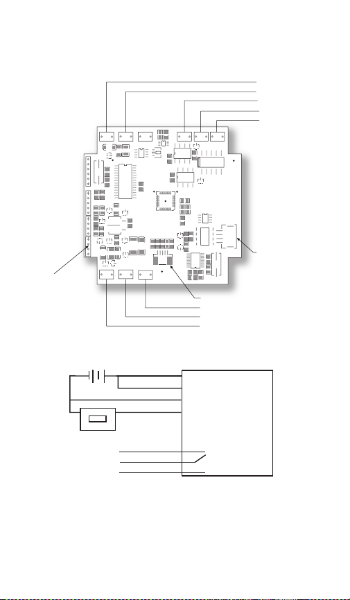
Line Powered/Loop Powered 4-20mA with (1) SPDT switch
(Type 2232 XAOU1) 7 conductor, 22 AWG shielded
– 26 –
Page 27

Installation Procedure for 2232 XAOU1:
ESD precautions should be taken. See page 31 for details.
1. Ensure all power is off/disconnected from the circuit.
2. Connect the white wire (P) to the positive power terminal.
3. Connect the green wire (O) to the negative power terminal.
4. Connect the red wire (M) to the positive power terminal.
5. Connect the black wire (N) to the positive meter terminal.
6. Connect the negative power terminal with the negative
meter terminal.
Note: Meter should be installed on the black wire only.
If red/black wires are connected prior to the green/white
and power is connected, output may be damaged due to
overloading.
Wiring the Switch:
Normally Open: Use the blue and brown wires.
Normally Closed: Use the orange and brown wires.
– 27 –
Page 28
LOOP+
LOOP–
T7
D9
D7
Y1
D10
C14
T9
U5
V1
F1D1
C3
C7
R7
R2
J1
1
1
J6
C2
R22
R20 C17
D11
U7
D14
D1
C15
R18
D5
R23
R24
D13
R14 R16
J3
J7
1
Q4
D16
D6
D15
D3
D12
T10
T12
T11
+24V
GND
EGN D
FID3
321CO21–
D8
Q2
J5
J3
C4
R9
R1 0
R1 1
R1 2
R1 3
Q1
C10
C9
R6
C5
L1
U4
FO7
R8
FID4
V2
R1
R5
C12
C13
C1
R4
C6
C8
DQ/TB 2003
Y2
J2
T4
T6
T5
FID2
C11
K1
K2
K2
D2
T3
T2
T1
V6
R21
ISO1
R15
ISO2
Q3
T8
ECND
FID6
FID5
R17
R19
Red Q
Blac k R
(N.O .) Blue
(N.C .) Orang e
(COM) Br ow n
(N.C.) Violet
(N.O .) Ye llo w
(COM) Gre y
Shiel d
Green
Whit e
Battery Input
Ke ypad Input
Sensor Input
(-exec.) S
(+exec.) T
SWITCH 1
SWITCH 2
+
+
–
POWER
SUPPLY
(+)
(–)
(–)
METER
PLC SCADA
GAUGE
–
V+
V–
White (T)
(+)
Red (Q)
Green (S)
Black (R)
Switch 1
Blue (NO)
Or a ng e ( NC )
Brown (Common)
•
Switch 2
Violet (NO)
Yellow (NC)
Grey (Common)
•
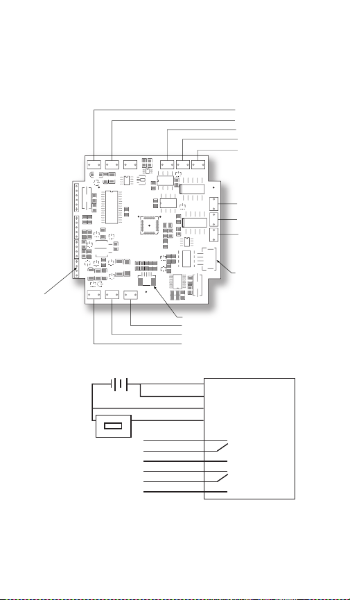
WIRING DIAGRAM
Line Powered/Loop Powered 4-20mA with (2) SPDT switches
(Type 2232 XAOU2) 10 conductor, 22 AWG shielded
– 28 –
Page 29

Installation Procedure for 2232 XAOU2:
ESD precautions should be taken. See page 31 for details.
1. Ensure all power is off/disconnected from the circuit.
2. Connect the white wire (T) to the positive power terminal.
3. Connect the green wire (S) to the negative power terminal.
4. Connect the red wire (Q) to the positive power terminal.
5. Connect the black wire (R) to the positive meter terminal.
6. Connect the negative power terminal with the negative
meter terminal.
Note: Meter should be installed on the black wire only.
Wiring Switch 1:
Normally Open: Use the blue and brown wires.
Normally Closed: Use the orange and brown wires.
Wiring Switch 2:
Normally Open: Use the violet and grey wires.
Normally Closed: Use the yellow and grey wires.
If red/black wired are connected prior to green/white wires
and power is connected, output may be damaged due to
overloading.
– 29 –
Page 30

GAUGE INSTALLATION:
The Ashcroft digital sanitary gauge comes standard with a
Tri-Clamp connection. Install the Tri-Clamp fitting to the
mating fitting using a gasket compatible with the process
media and clamp (mating fitting, gasket, clamp provided
by others).
NEVER TIGHTEN GAUGE THREADS BY HOLDING THE
BODY OF THE GAUGE. DOING SO MAY DAMAGE THE
GAUGE AND MAKE THE GAUGE INOPERABLE.
Battery Installation and Replacement:
The Type 2032 comes standard with batteries installed.
The 3˝ case uses qty (2) AA alkaline batteries, the 4
1
⁄2˝ case
uses qty (2) C alkaline batteries. Use either Duracell
MN2400, MX2400 or Energizer E92BP, X92RP AAA alkaline, non-rechargeable batteries.
Batteries have a life of approximately 1500 hours (3˝ case).
3600 hours (4
1
⁄2˝ case). Battery life is dependent on gauge
usage, backlite settings and power off settings. When the
lower bar of the battery icon of the gauge display flashes,
the gauge has approximately 7 hours of life remaining.
To replace the batteries (3˝ case):
1) Remove the single screw on the back of the gauge case.
2) Hold the keypad in the palm of hand.
3) Carefully remove the two batteries from the holder and
replace batteries. Use only AA alkaline non-rechargeable
batteries
1
To replace the batteries (4
⁄2˝ case):
1) Remove the ring on the front of the gauge case.
2) Looking at the gauge case, carefully pull the front face
out of the case.
3) Lay the gauge, face down on a flat surface.
4) Carefully remove the two batteries from the holder and
replace the batteries. Use only C alkaline non-rechargeable batteries.
– 30 –
Page 31

ESD PRECAUTIONS
Care should be taken to minimize exposure to ESD.
Proper proto-call should be followed as outlined in:
ANSI/ESD S20.20-2007
ESD ADV1.0-2009
ANSI/ESD S541-2008
Additional ESD Precautions on Proper Handling:
Avoid carpets in cool, dry areas as well as other static
generating materials such as plastic, cellophane, paper, or
cardboard.
Leave digital gauges in their anti-static packaging until
ready to be installed.
Dissipate static electricity before handling the digital
gauge or using keypad by touching a well-grounded metal
object, such as the system unit unpainted metal chassis.
If possible, use antistatic devices, such as wrist straps and
floor mats.
When installing batteries, avoid touching (including clothing) the contacts and components.
When making wiring connection to digital gauge terminals, place digital gauge on grounded mat prior to making
connection, and take care to avoid touching (including
clothing) any components.
Take care when connecting or disconnecting cables. A
damaged cable can cause a short in the electrical circuit.
When disconnecting a cable, always pull on the cable connector, case, or strain-relief loop, not on the cable itself.
– 31 –
Page 32
4.00
1.860
.17
CLAMPING RING (1278G ONLY)
WASHER
SPACER POST
(3 REQ’D)
“B” (3 REQ’D)
PANE L
MOUNTING
RING
6˝ RING
DIA.
5.65˝
PANEL
OPENING
5/16˝ MAX PANEL
THICKNESS
Notes:
1) Do not mix ages or brands of batteries.
2) Do not replace batteries in hazardous areas.
3) To provide maximum battery life, replace both batteries
4) To provide maximum battery life, replace both batteries.
Pipe to which gauge is attached must be properly
grounded.
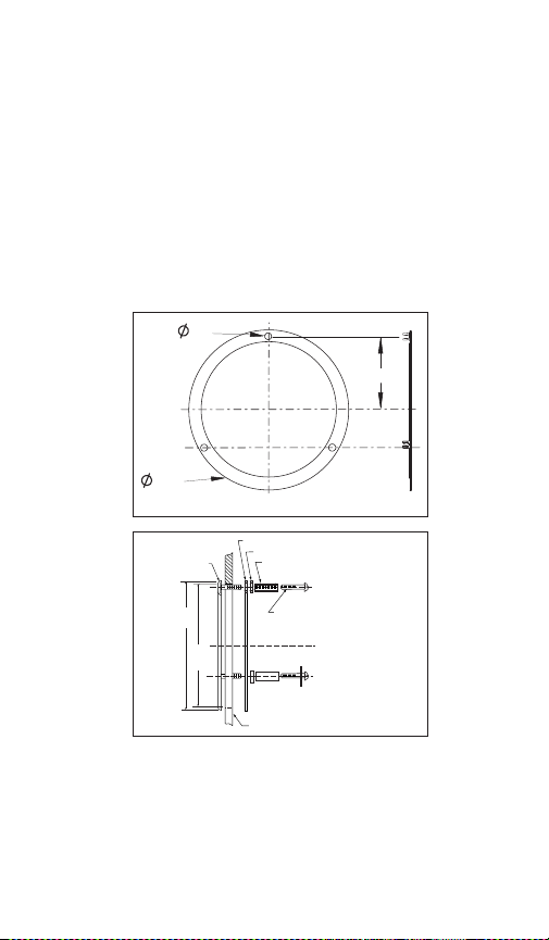
PANEL MOUNTING DIMENSIONS:
HOLE
CUTOUT
DIAMETER
3.406
13
⁄32±1⁄32)
(3
3˝ CASE
Ashcroft Inc.
250 East Main Street | Stratford, CT 06614-5145
41⁄2˝ CASE
Tel: 203-378-8281 | Fax: 203-385-0602
e-mail: [email protected] | www.ashcroft.com
© Ashcroft Inc. 7/08 I&M008-10162 Rev. 09/11
– 32 –
 Loading...