

Page 1
Data Sheet
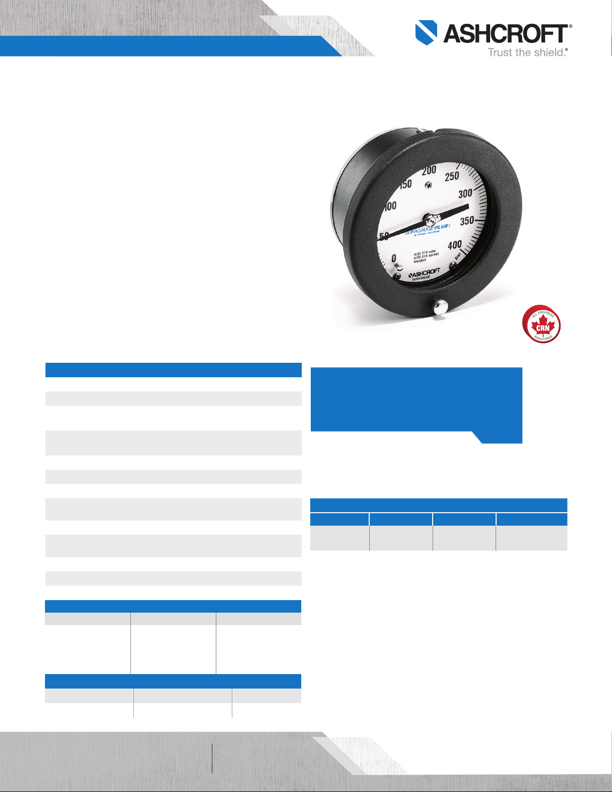
1377 Duragauge® Pressure Gauge
FEATURES
Solid front safety case with pressure relief back
Dial sizes 4½˝, 6˝ and 8½˝
±0.5% of span (ASME B40.100 Grade 2A)
Customizable dial printing options
TYPICAL USES
Refineries
Chemical and petrochemical plants
Offshore oil rigs
Water and wastewater pressure control
Pulp and water
Mining and metals
Equipment skids
Specialized OEM equipment
1377
41⁄2˝ dial size
SPECIFICATIONS
Accuracy: ±0.5% of span (ASME B40.100 Grade 2A)
Dial Sizes: 41⁄2˝, 6˝, 81⁄2˝
Process Connection:1⁄4 NPT, 1⁄2 NPT,
Process Connection
Location:
Ranges: Vacuum, compound to 30,000 psi
Case Style: Solid front with pressure relief back
Movement: Rotary, adjustable, 400 SS, Teflon® coated
Window Material:
Pointer: Micrometer, adjustable, aluminum, maximum
Weather Protection: Dry case: Case not sealed, recommended for
Mounting: Stem, surface, flush or remote
Dampening: PLUS!™ Performance
Approvals: CRN
WETTED COMPONENTS
Bourdon Tube Process Connection Joints
316L SS 316L SS Welded
316L SS Steel Welded
K-Monel® 500 Tube Monel® 400 Welded
C510 Phos. Bronze Brass Silver brazed
NON-WETTED COMPONENTS
Case Ring Back Cover
Aluminum, black epoxy Steel, hinged, black enamel 300 SS
9
⁄16 -18 UNF-2B (high pressure connection)
Lower, back
Glass (STD.), safety glass, acrylic,
non-glare glass (OPT.)
weather protected environment only
KEY BENEFITS
• Ideal for panel mounting
• Available 8½˝ dial size for remote reading
MIN/MAX TEMPERATURE LIMITS
Version Ambient Process Storage
Dry
-20°F to 200°F
(-29°C to 93°C)
-20°F to 250°F
(-29°C to 121°C)
-40°F to 250°F
(-40°C to 121°C)
All specifications are subject to change without notice.
All sales subject to standard terms and conditions.
©2019 Ashcroft Inc. 1377_gauge_ds2.0, Rev E, 06/19
ashcroft.com
of 41
info@ashcroft.com
1.800.328.8258
Page 2
Data Sheet
1377 Duragauge® Pressure Gauge
ORDERING CODE Example:
Dial Size/Model Code
451377 - 41⁄2˝ aluminum case 451377
601377 - 6˝ aluminum case
851377 - 81⁄2˝ aluminum case
System (tube and process connection)
A - Bronze tube, brass process connection, max. pressure connection 1,000 psi
P - K-Monel® 500 tube, Monel® 400 process connection, max. pressure 30,000 psi
R - 316L SS tube, steel process connection, max. pressure 20,000 psi
S - 316 SS tube and 316L SS process connection, max. pressure 20,000 psi S
WW - Inconel® 718 tube and process connection
Case Design
S - Solid front case, dry
Process Connection Sizes
02 - 1⁄4 NPT Male, N/A for ranges over 20,000 psi
04 - 1⁄2 NPT Male, N/A for ranges over 20,000 psi
09 - 9⁄16 18 UNF-2B, high pressure fitting, standard for pressures over 20,000 psi
Process Connection Location
L - Lower
B - Back
D - Side (3 o’clock)
E - Side connection (9 o’clock)
T - Top connection
Options (If choosing an option(s) must include a “X”)
Dampening
LL - PLUS!™ Performance
NZ - PLUS!™ Performance, silicone free
TS - Throttle screw (standard with PLUS!™ Performance)
Dial
DA - Dial marking (text marking on the dial)
D3 - DuraVis™ Retroreflective Dial (4½˝ case only)
Windows/Pointers
PD - Acrylic window
SG - Safety glass
NG - Non-glare glass (4
EP - Maximum pointer (adjustable)
SH - Red set hand stationary
Other
6B - Cleaned for gaseous, oxygen service
NH - Stainless Steel tag wired to case
AB - Gauges calibrated to compensate for absolute pressure
OS - Overload stop
VS - Underload stop
HY - Hydrostatic/pneumatic testing (system pressurized to 150% of rated system pressure for 5 minutes. Overload stop standard.)
C4 - Individual calibration chart (in accordance with ASME B40.100:2013. Accuracy traceable to NIST)
Range (coding examples only, see range table on page 3 for all standard ranges)
Single Scales
15# - 15 psi 15#
1BR - 1 bar
1KG - 1 kg/sm
100KP - 100 kPa
Dual Scales
15#/BR - 15 psi inner scale, 1 bar outer scale
1BR/# - 1 bar inner scale, 15 psi outer scale
1
⁄2˝ and 6˝ cases only)
2
451377
S S 04 L XLL 15#
04
L
X__
LL
All specifications are subject to change without notice.
All sales subject to standard terms and conditions.
©2019 Ashcroft Inc. 1377_gauge_ds2.0, Rev E, 06/19
ashcroft.com
of 42
info@ashcroft.com
1.800.328.8258
Page 3

Data Sheet
1377 Duragauge® Pressure Gauge
STANDARD PRESSURE RANGES
psi bar kPa mPa kg/cm
30IMV N1BR N100KP N1MP N1KG
Vacuum
Compound
Positive Pressure
– N1/0.6BR N100/60KP 0.1/0.06MP N1/0.6KG
V/15# – – – –
– N1/1.5BR N100/150KP N.1/0.15MP N1/1.5KG
V/30# – – – –
– N1/3BR N100/300KP N.1/0.3MP N1/3KG
V/60# – – – –
– N1/5BR N100/500KP N.1/.5MP N1/5KG
V/100# – – – –
– N1/9BR N100/900KP N.1/.9MP N1/9KG
15# 1BR 100KP 0.1MP 1KG
20# – – – –
– 1.6BR 160KP 0.16MP 1.6KG
30# – – – –
– 2.5BR 250KP 0.25MP 2.5KG
60# 4BR 400KP 0.4MP 4KG
– 6BR 600KP 0.6MP 6KG
100# – – – –
120# – – – –
– 10BR 1000KP 1MP 10KG
160# – – – –
200# – – – –
– 16BR 1600KP 1.6MP 16KG
300# – – – –
– 25BR 2500KP 2.5MP 25KG
400# – – – –
500# – – – –
600# 40BR 4000KP 4MP 40KG
800# – – – –
– 60BR 6000KP 6MP 60KG
1000# – – – –
1500# 100BR 10000KP 10MP 100KG
2000# – – – –
– 160BR 16000KP 16MP 160KG
3000# – – – –
– 250BR 25000KP 25MP 250KG
4000# – – – –
5000# – – – –
6000# 400BR 40000KP 40MP 400KG
8000# – – – –
– 600BR 60000KP 60MP 600KG
10000# – – – –
15000# 1000BR 100000KP 100MP 1000KG
20000# - - - -
- 1600BR - 160MP 1600KG
30000# - - - -
2500BR - 250MP 2500KG
50000# - - -
- 4000BR - 400MP 4000KG
80000# - - -
- 6000BR - 600MP 6000KG
100000# - - - -
2
All specifications are subject to change without notice.
All sales subject to standard terms and conditions.
©2019 Ashcroft Inc. 1377_gauge_ds2.0, Rev E, 06/19
ashcroft.com
of 43
info@ashcroft.com
1.800.328.8258
Page 4

Hole in
3 Mounting studs
equally spaced on
S
Data Sheet
1377 Duragauge® Pressure Gauge
DIMENSIONS in [ ] are millimeters
Drawings are for reference only, consult Ashcroft for specific dimensional drawings.
Dial Size
Inches
41⁄2
6
1
8
⁄2
A B C D E F G H K M P S T U CC LL
7
3
1
3
5
15
6
[152]
9
7
[192]
10
[257]
2
⁄8
4
⁄4
1
⁄16
5
⁄8
1
⁄8
[73]
[121]
7
⁄16
2
⁄8
[73]
[121]
7
1
2
⁄8
⁄16
[73]
[121]
3
4
⁄4
3
4
⁄4
[27]
[137]
1
1
⁄16
[27]7[178]
1
1
[27]
5
⁄16
9
[244]
⁄8
3
[41]
[100]
5
1
⁄8
4
[41]
[114]
5
1
⁄8
[41]6[152]
3
⁄16
1
⁄8
1
[35]
[27]
1
3
⁄2
1
⁄8
1
[35]
[27]
3
1
⁄8
1
[35]
[27]9[229]
1377 4½˝ and 6˝ lower connection 1377 4½˝ and 6˝ back connection
A
B
S
U
Nuts & washers
not supplied by
Ashcroft
C
T
M
panel
F
G
H
CC threaded
E dia. Bolt Circle
P
D
K
LL
1
1
1
⁄16
⁄16
⁄16
7
4
[124]
1
6
[165]
Weight
(lbs)
1
5
5
⁄8
2
⁄8
[54]
⁄2
2
[54]
2
[54]
⁄8
[16]
[16]
1
5
⁄8
⁄8
[16]
[16]
1
5
⁄8
⁄8
[16]
[16]
⁄8
5
⁄8
5
⁄8
3
[19]
3
[19]
3
[19]
⁄4
⁄4
⁄4
#10-24
1
⁄4-20
1
⁄4-20
1
⁄8-1⁄2
[3][13]
1
⁄8-1⁄2
[3][13]
1
⁄8-1⁄2
[3][13]
2.5
2.5
4.5
3 Mounting studs CC threaded
equally spaced on E dia. Bolt Circle
All specifications are subject to change without notice.
All sales subject to standard terms and conditions.
©2019 Ashcroft Inc. 1377_gauge_ds2.0, Rev E, 06/19
1377 8½˝ lower connection 1377 8½˝ back connection
Nuts & washers
not supplied by
A
B
G
T
P
D
U
T
H
K
LL
ashcroft.com
info@ashcroft.com
1.800.328.8258
Ashcroft
C
F
M
Hole in
panel
of 44
 Loading...