

Page 1
Installation Instructions for
ROTARY MAGNET
MAGNET
P
OINTER
HIGH
0
1
0
2
0
3
0
40
DIAPHRAGM
LOW
5
0
REED SWITCH
View from high pressure side
Increase set point
counter clockwise
ASHCROFT®Model 1133
Differential Pressure Gauge/Switch
For efficient working of your gauge, please read all instructions
carefully before attempting to install.
CAUTION: Do not exceed maximum operating pressure given
on the gauge label. Check fluid compatibility with wetted parts
before use.
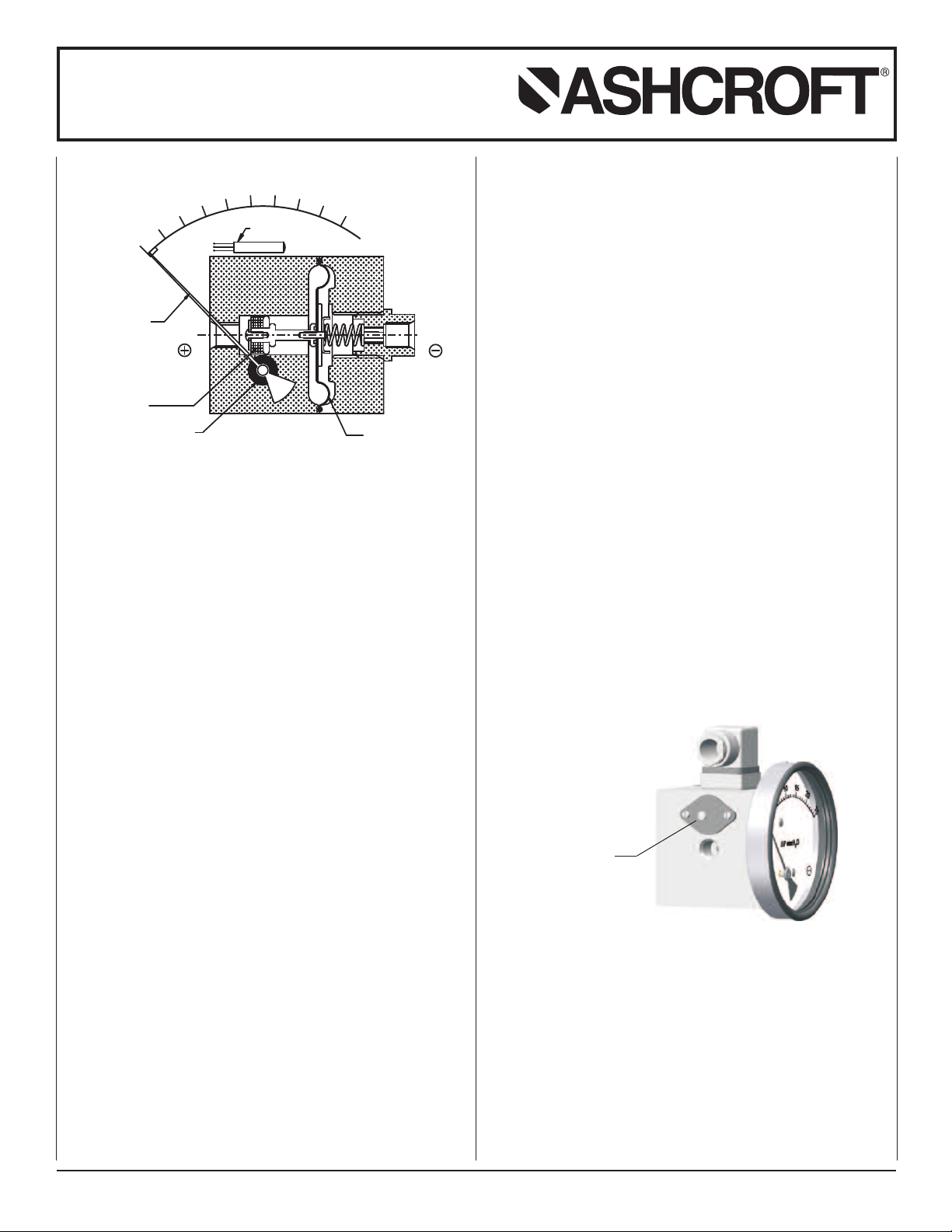
OPERATING PRINCIPLE
High and Low pressures are separated by a sensor assembly
consisting of a magnet, diaphragm and a range spring. The
difference in pressure causes the sensor assembly to move in
proportion to the change against a range spring.
A rotary magnet, located in a separate body compartment and
isolated from the acting pressures is rotated by a magnetic
coupling following the linear movement of the sensor assembly.
A pointer attached to the rotary magnet indicates differential
pressure on the dial.
SWITCH: Reed switches (optional) are located adjacent to the
pressure chamber and are activated by the magnetic field of
the sensor assembly.
Note: The gauges are calibrated to give ±2% full scale accuracy on ascending readings.
INSTALLATION
For better performance the gauge should be mounted horizontally with the dial vertical. Depressurize the system and connect the high and low pressure lines of your system to the
“High” and “Low”ports of the gauge, respectively.
It is recommended to use “O” rings with male connectors to
avoid excessive tightening and to prevent leakage (for parallel
threads). The gauge is now ready for operation. Apply “High”
and “Low”pressures simultaneously, to avoid damage to the
internal parts.
The Model 1133 uses a large convoluted diaphragm designed
for low differential pressure. It can withstand maximum operating
pressure up to 500 psi for all ranges. If pressure exceeds the
rated maximum pressure, the gauge will be damaged.
PRECAUTIONS
Do not connect “High” and “Low” ports to the wrong pipe ends.
Do not subject the gauge to excessive vibration. The gauge is
never to be used in an area where a magnetic field is present.
It may show the wrong readings.
As the gauge works on a magnetic coupling principle, use only
non-magnetic fittings, parts, etc. in areas closer than 2˝ on all
sides, otherwise calibration will be affected. Panel mounted
gauges should be installed in non-ferrous panel material.
Do not try to open any part of the gauge for any reason, because if not reassembled properly calibration will be affected.
SWITCH SETTING
Please follow these instructions when your differential pressure
gauges are supplied with a switch. The switches are normally
Model 1133
Large Convoluted Diaphragm
factory set to save time the customer time. However, they are
field adjustable.
CAUTION: Supply voltage should not exceed switch rating.
For higher supply, use of relay circuit is recommended.
SWITCH ADJUSTMENT
The following procedure must be done by putting the gauge on
test bench or while in actual service. The switch adjustment
screw is located on the plastic cover. Rotate the screw
clock
wise to increase the setpoint and clockwise to decrease
counter
the setpoint. One or two trials may be necessary to attain the
exact setpoint.
© Ashcroft Inc., 250 East Main Street, Stratford, CT 06614-5145, USA, Tel: 203-378-8281, Fax: 203-385-0357, www.ashcroft.com
All sales subject to standard terms and conditions of sale. I&M008-10086-12/01 07/13
Page 2
L
or(+)
Lor(+)
L
L
oad
Nor(-)
Nor(-)
N
N
or(-)
1
3
2
E
B
R
E
1
3
2
SPST
Switch
Loadfor
Loadfor
Switch #1
3
2
E
1
3
1
E
R
B
2
B
Switch #2
Switch #1
Switch #2
Installation Instructions for
L
oad
NC
N
O
1
3
2
E
Lor(+)
Nor(-)
N
or(-)
Y
R
3
1
2
E
B
SPDT
Switch
ASHCROFT®Model 1133
Differential Pressure Gauge/Switch
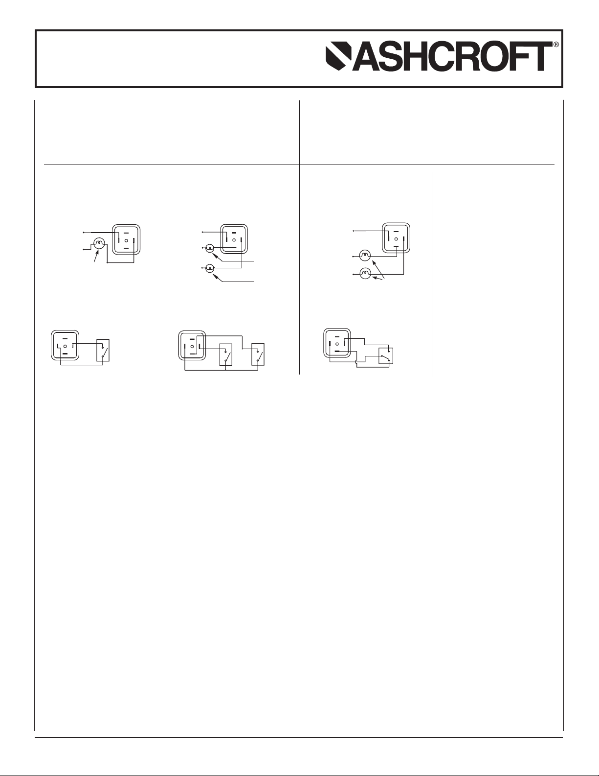
SPST SWITCH
Specifications
Contact Rating : 10 VA ac (rms) or dc (max)
Switching Current : 0.5 Amp ac (rms) or dc (max)
Switch Voltage : 100 Vac/Vdc (max)
PDT SWITCH
S
pecifications
S
Contact Rating : 3 VA ac (rms) or dc (max)
Switching Current : 0.3 Amp ac (rms) or dc (max)
witch Voltage : 30 Vac/Vdc (max)
S
ONE SPST SWITCH TWO SPST SWITCHES
Reed Switches and
DIN Plug Connection
View of socket for supply connections
View of plug after removing the socket View of plug after removing the socket
R = Red; B = Black; Y = Yellow; L = Live or + Supply; N = Neutral or – Supply. *Body to be suitably grounded while using gauge + switch and only switch.
Reed Switches and
DIN Plug Connection
View of socket for supply connections
ONE SPDT SWITCH
Reed Switches and
DIN Plug Connection
View of socket for supply connections
View of plug after removing the socket
© Ashcroft Inc., 250 East Main Street, Stratford, CT 06614-5145, USA, Tel: 203-378-8281, Fax: 203-385-0357, www.ashcroft.com
All sales subject to standard terms and conditions of sale. I&M008-10086-12/01 07/13
 Loading...